-
What's New
-
This section of the web site has been organized in chronological order, with the most recent progress and commentary first and working backwards to when we moved into the house. More photos and other information is contained in the other sections of the web site.
December 2023 / January 2024 | CPR Boundary Substation mock-ups
Over the years we have added commercial models as placeholders for several mainline stations. Recently, a decision was made to remove these and build some mock up buildings based on the specific prototype structures. This involved research of the actual prototype buildings for which we located numerous photographs and some relevant plans.
In conjunction with these efforts, one of our regular crew offered to produce 3D printed windows and doors for these buildings since no commercially available products would be satisfactory. -
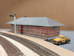
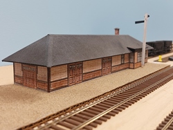
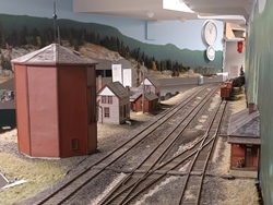
South Slocan
-
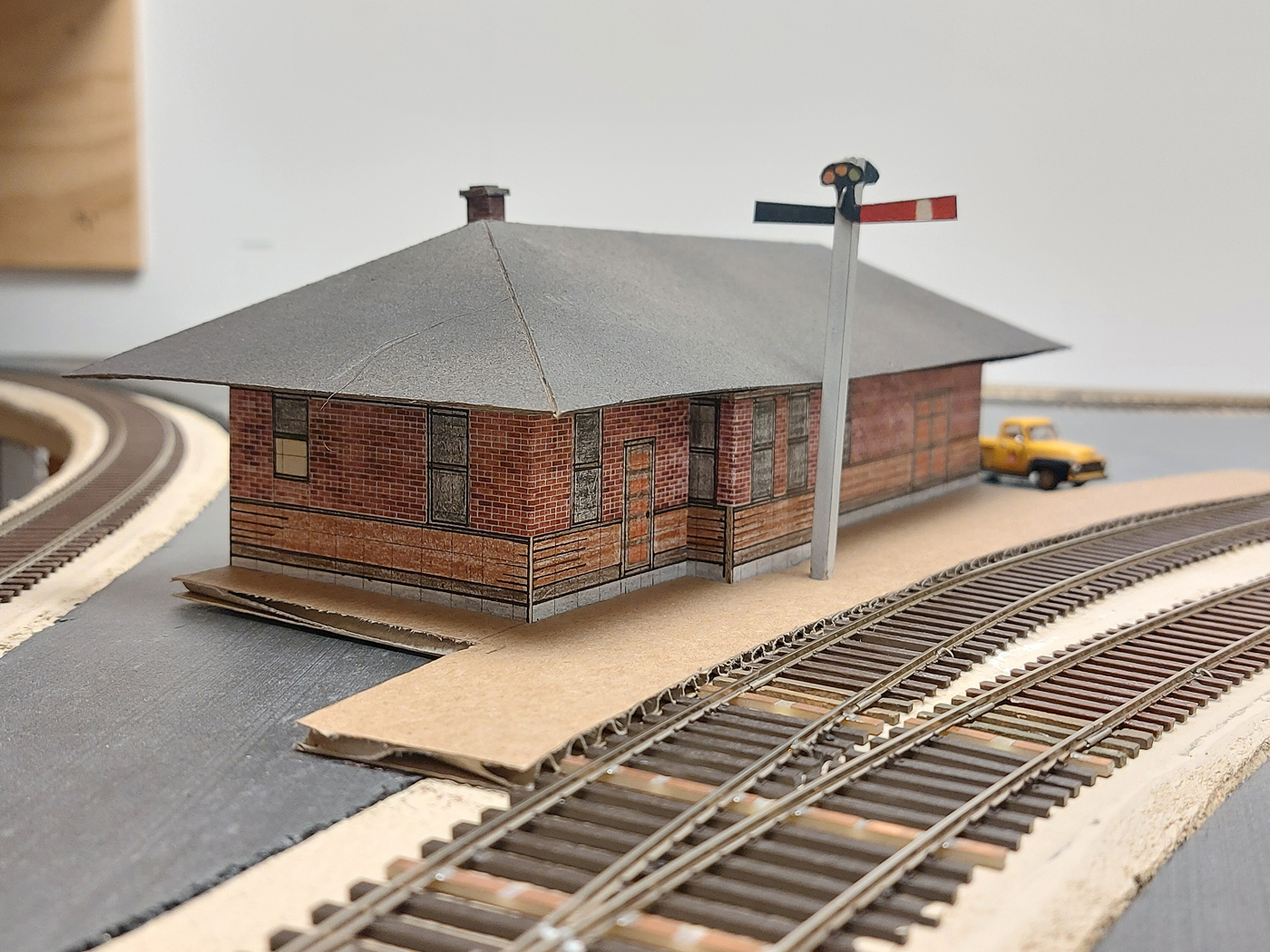
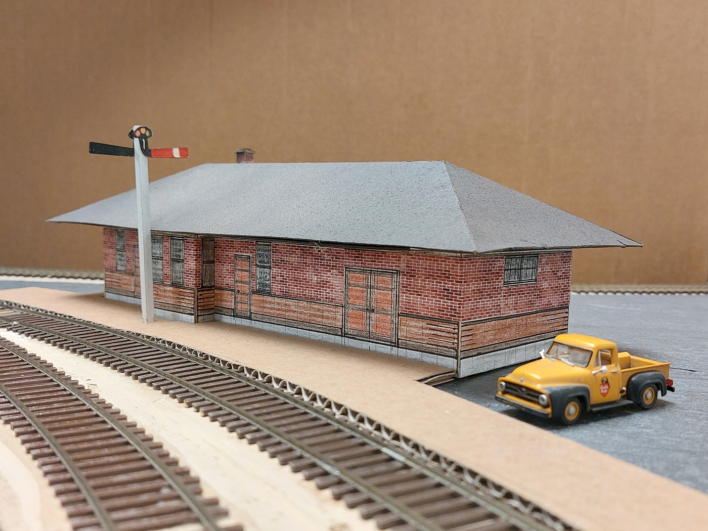
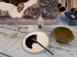
This location is where the Slocan Subdivision branchline joins the Boundary Subdivision mainline, and a fairly modest station existed there until it was removed in the late 70’s. Working with a poor CPR plan and a bunch of photographs, I prepared scale plans of the elevations of the building. These were reduced to HO scale and glued to cardboard. Next, they were colored with pencil crayons, cut out, and reinforced with strip wood bracing. One unique thing on this mock up was the use of brick paper products from Clever Models ( http://clevermodels.squarespace.com ) to represent the insulbrick that was on the upper section of prototype building walls.
Here are a couple photos of the completed mock up;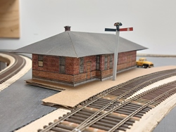
-
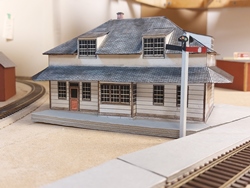
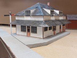
Castlegar
-
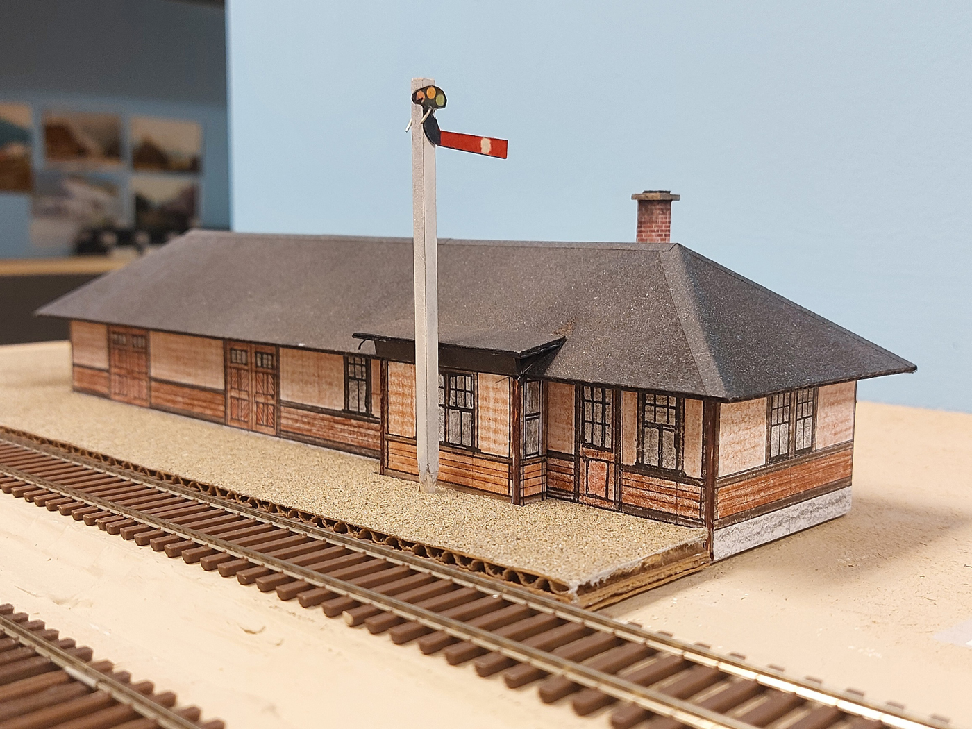
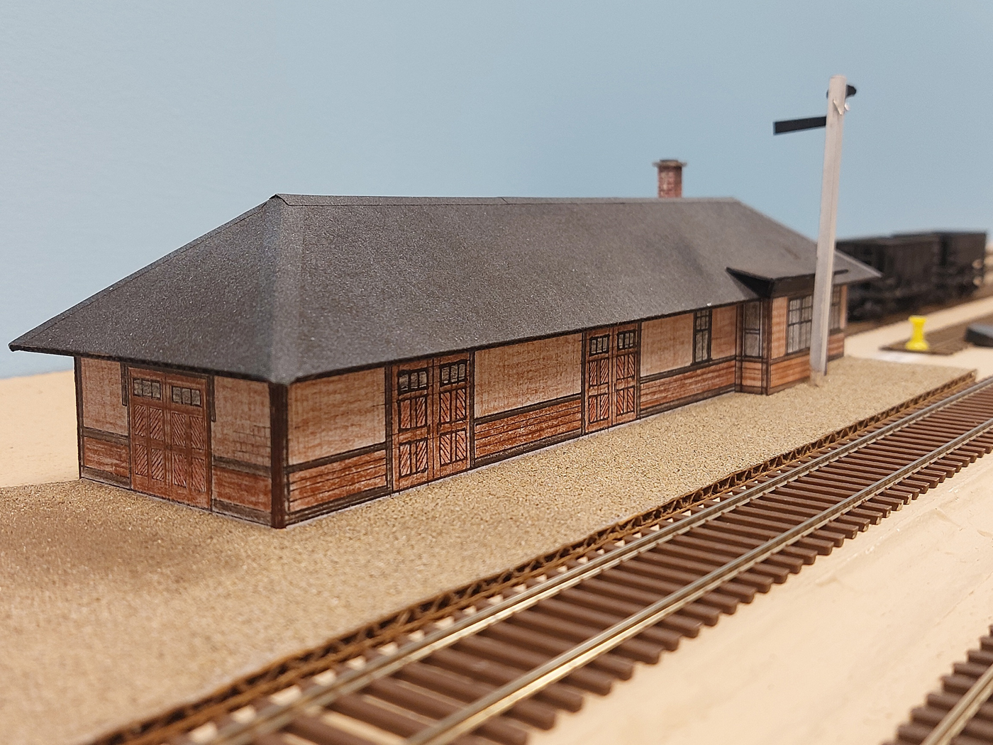
This location is where the Rossland Subdivision branchline to the Cominco Smelter joins the Boundary Subdivision mainline. Here, there is a unique station that was built by the predecessor to the CPR; Columbia & Western Railway. I was fortunate to have copies of the prototype plans for this building and HO scale CAD files prepared by a friend. Both had inaccuracies relative to how the Actual station existed in my era, however they were extremely helpful regardless. The building is a heritage building and hos been relocated and preserved – so, a friend who lives close by did some field measuring to verify discrepancies between the documents and the actual building.
Because this is just a mock up, it was decided to simply print the CAD drawings on heavy cardstock to produce the mock up for now. It was built using the same basic technique as the South Slocan station, except that the roof areas were colored using pan pastels because the white cardstock was too glaring.
This is a complicated building, and constructing a mock up gave me helpful insight into the challenges I would face when constructing the final model.
Here are a couple photos of the completed mock up; -
-
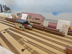
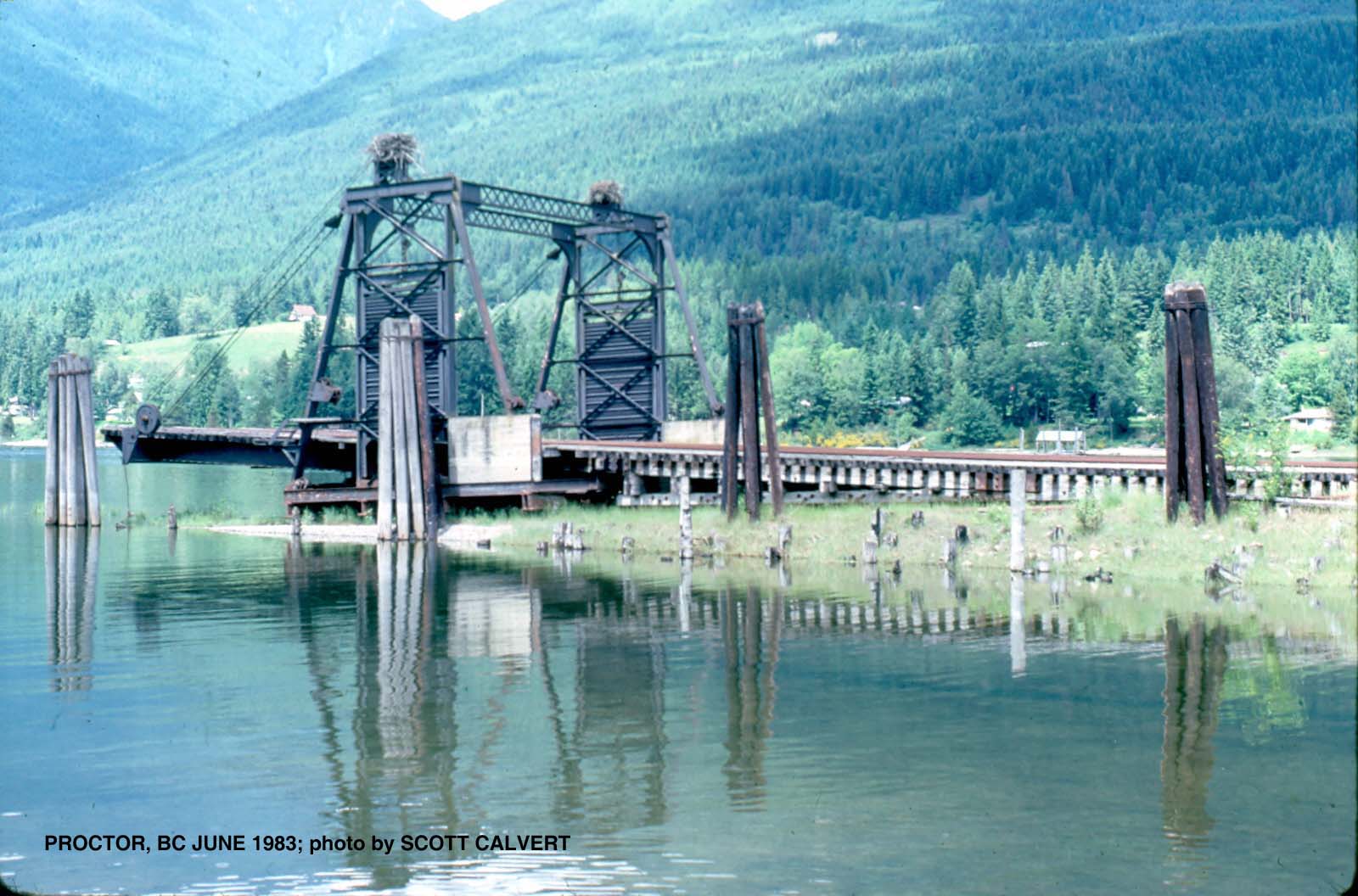
Procter
-
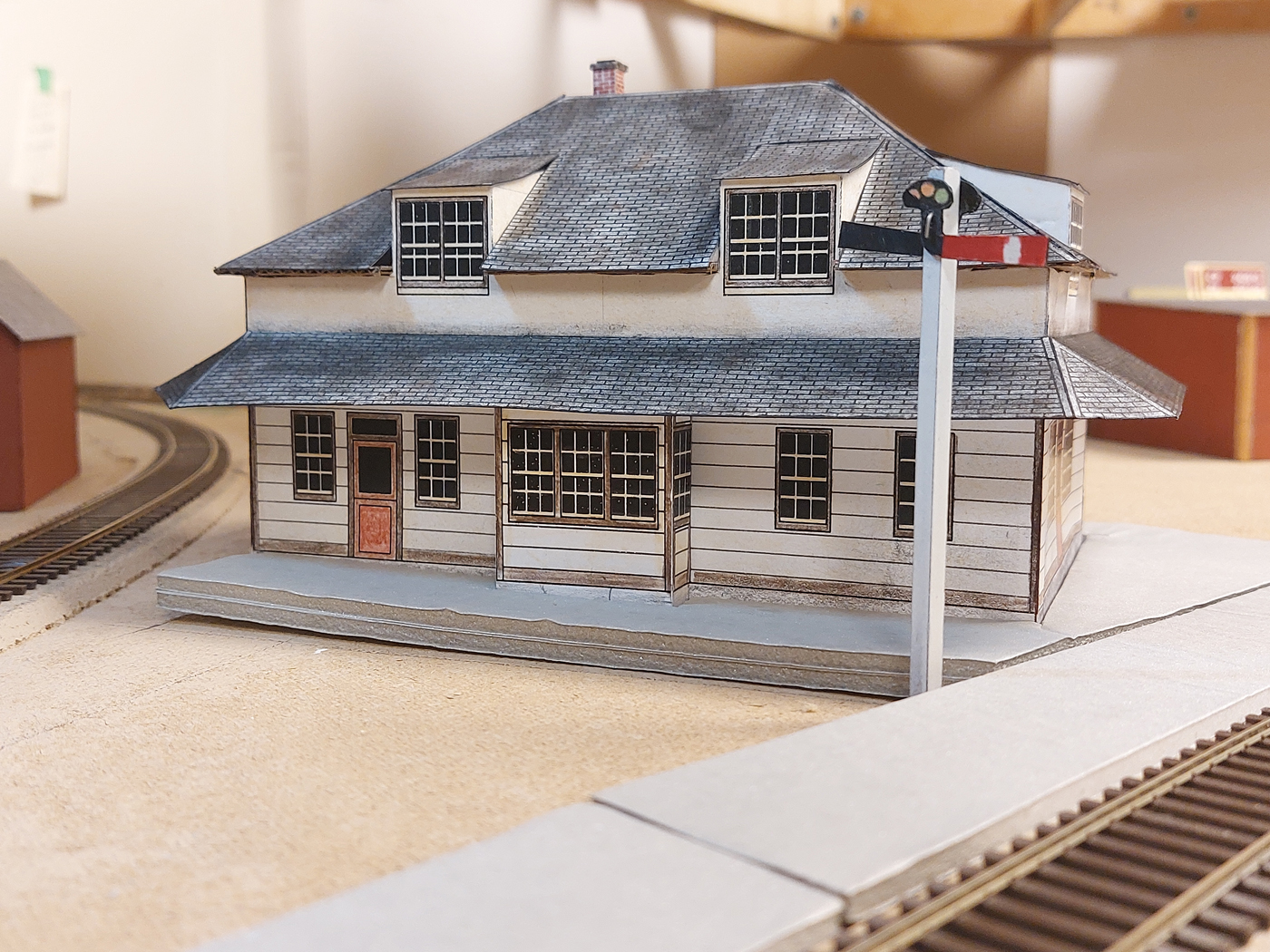
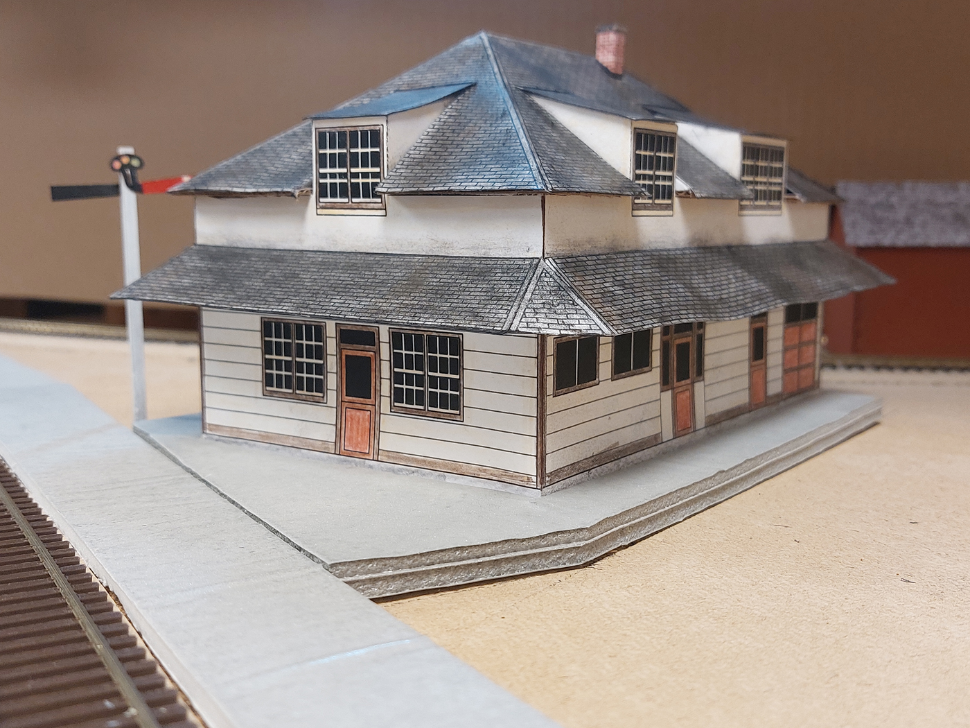
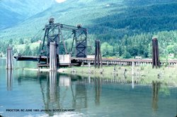
This location at Procter is located along the Nelson Subdivision where the Kootenay Lake barge operation had a three track transfer slip. In the early years of operation, this was a very busy junction necessitating a larger station that the other locations. It also had a residence annex on the rear for the agent.
We have many excellent photos of this building, but no specific CPR plans. However, it was determined that the building was an enlarged and slightly modified version of a CPR Standard #4 station for which we did have CPR plans.
Therefore, by using the photos and CPR plans, again I prepared HO scale drawings of the wall elevations. The mock up building was constructed using the same general techniques as the South Slocan station.
Here are a couple photos of the completed mock up;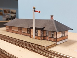
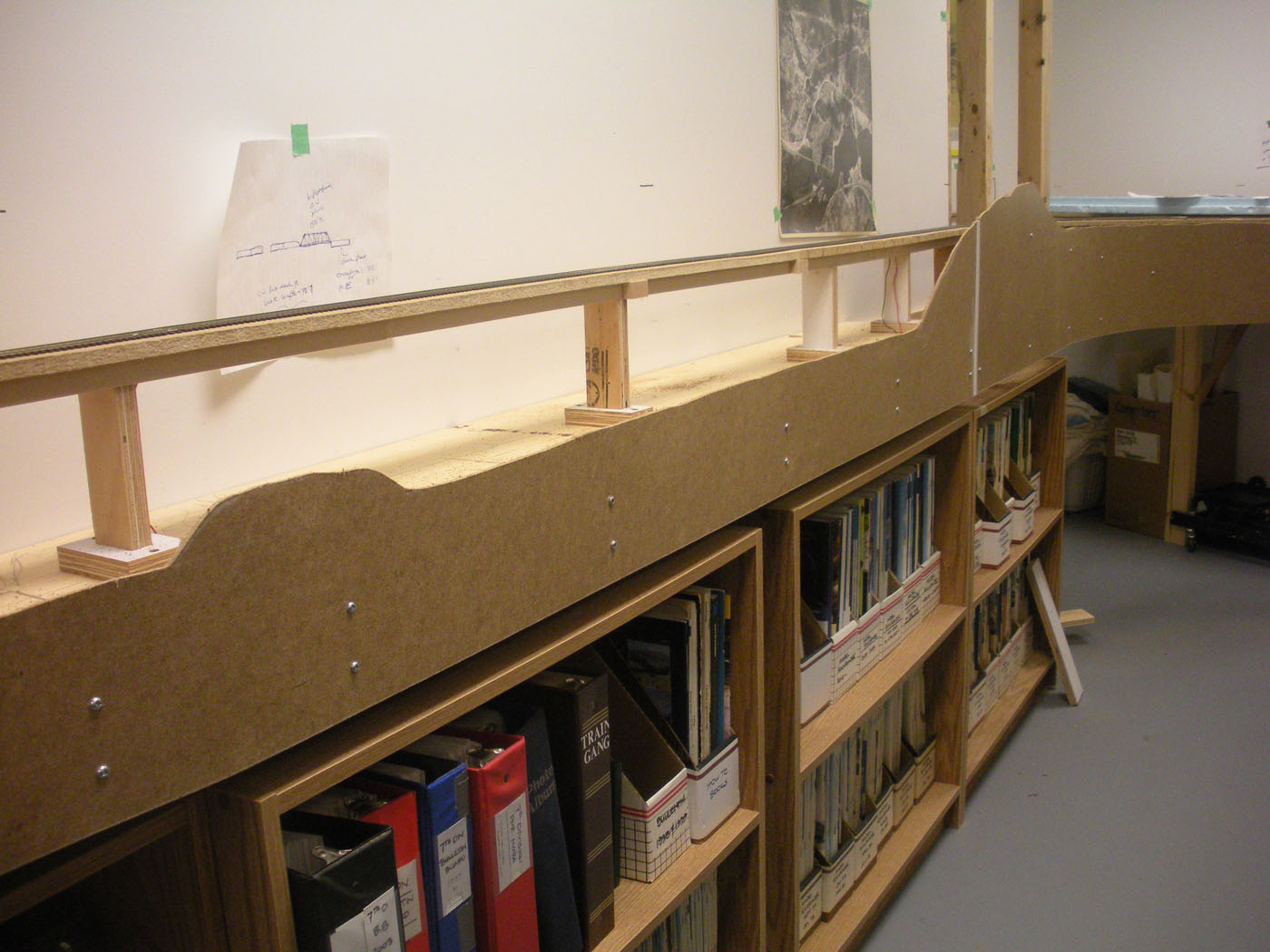
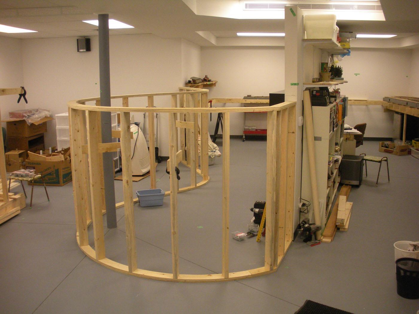
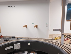
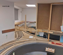
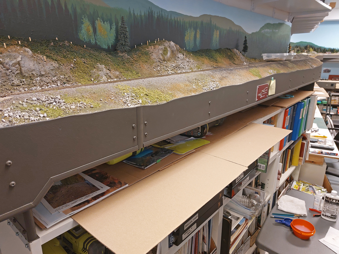
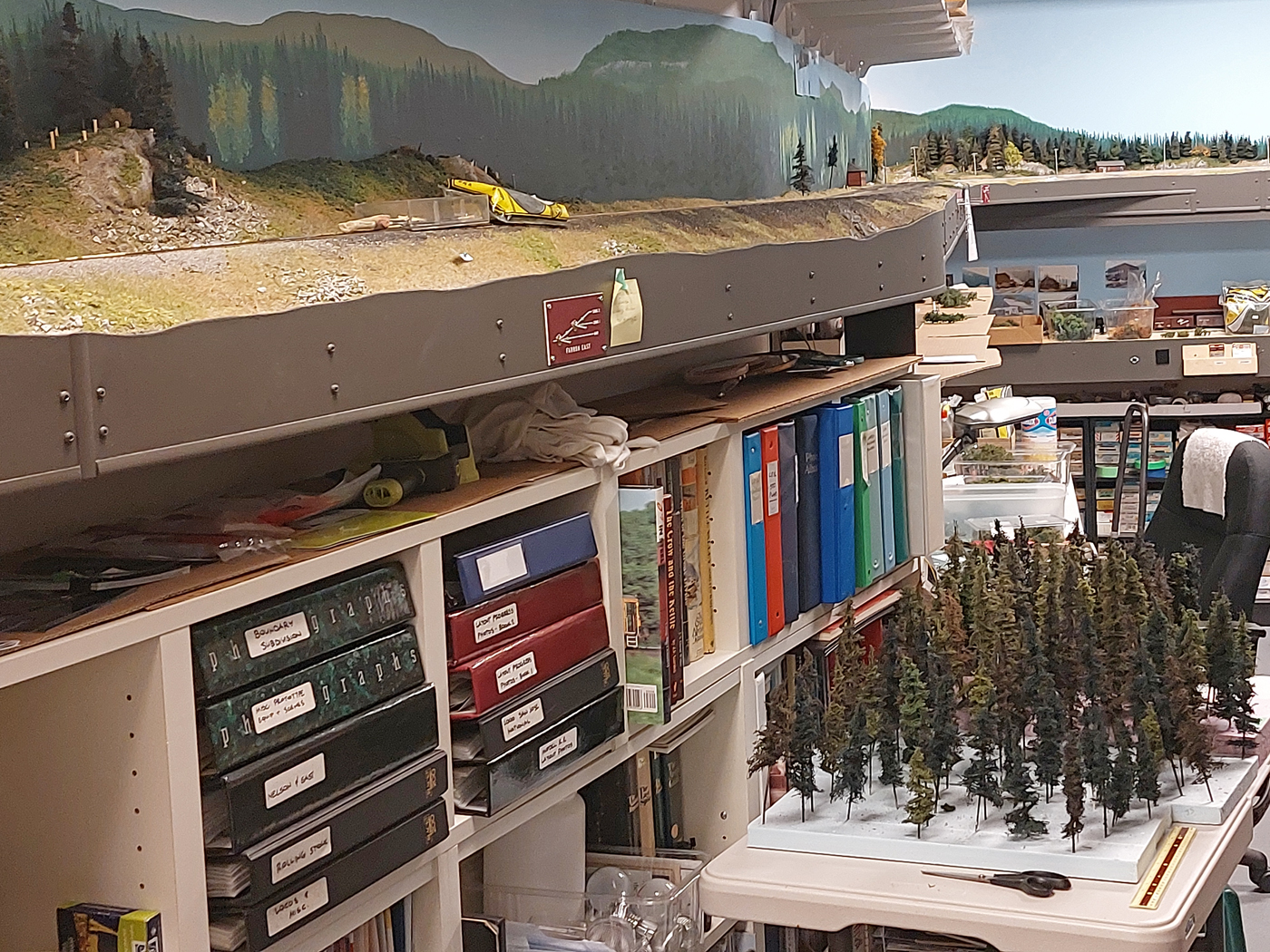
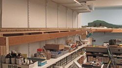
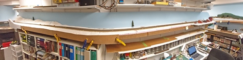
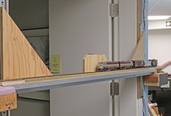
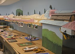
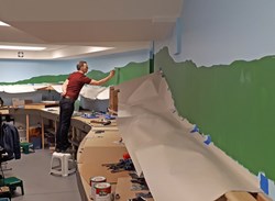
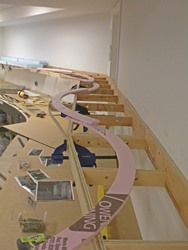
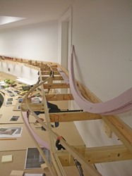
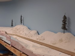
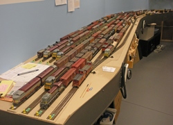
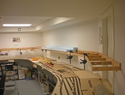
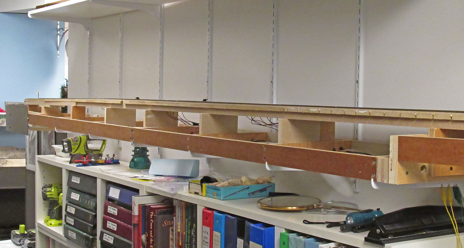
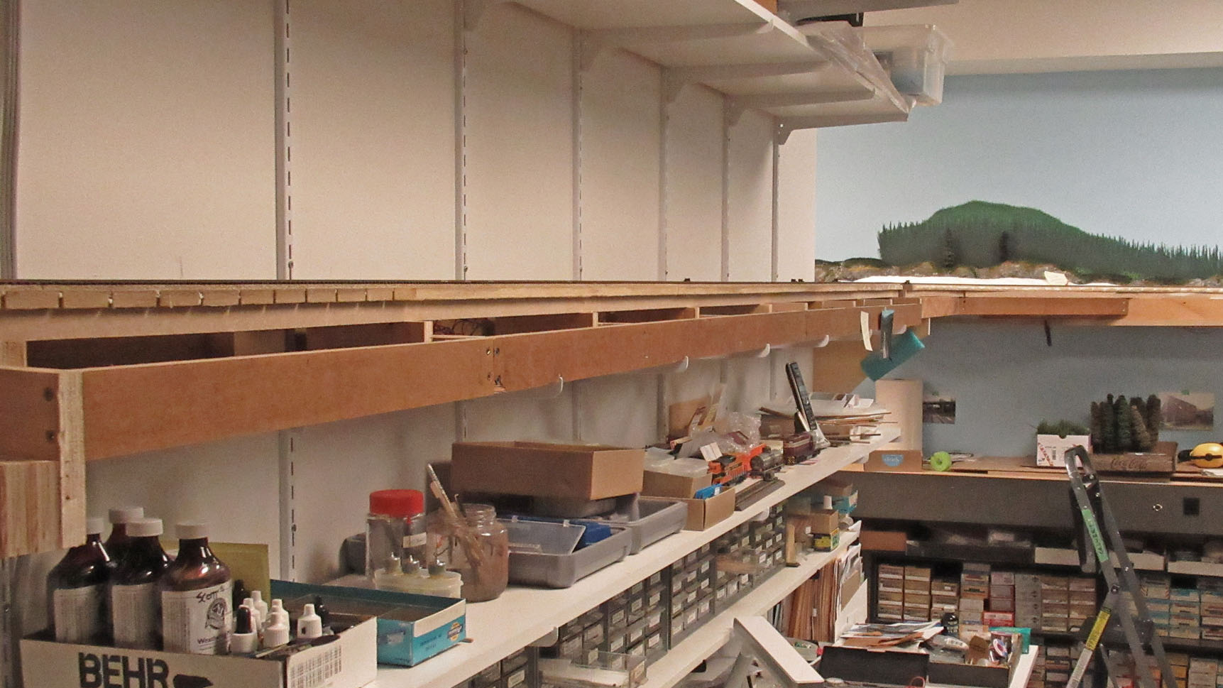
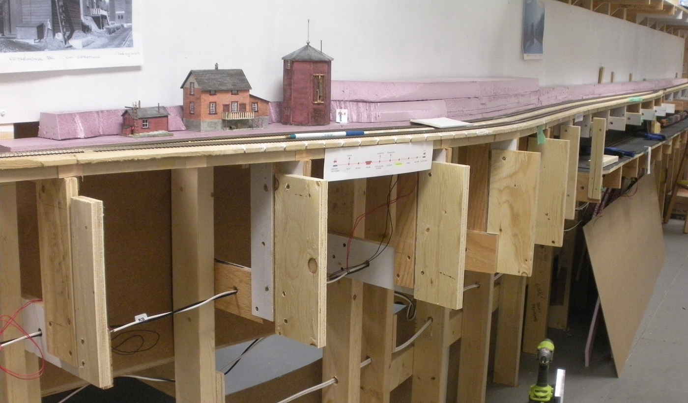
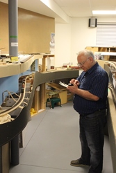
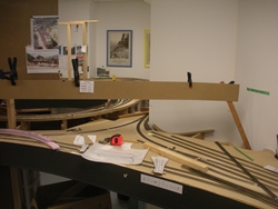
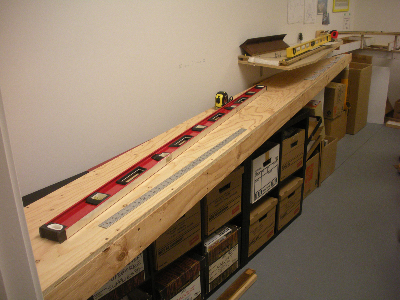
November 2023 | CPR Boundary Subframing & back Drop Mock-Ups
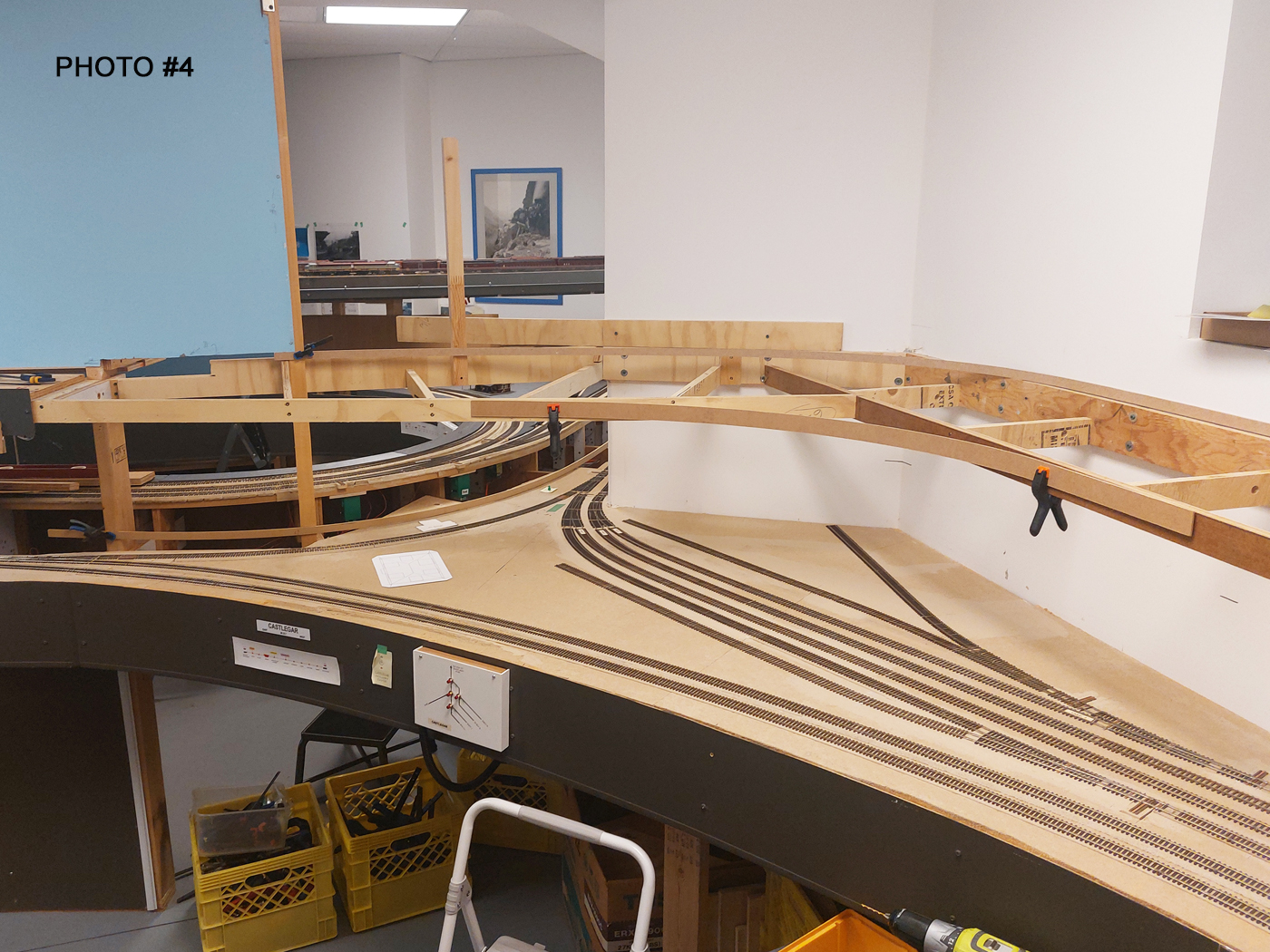
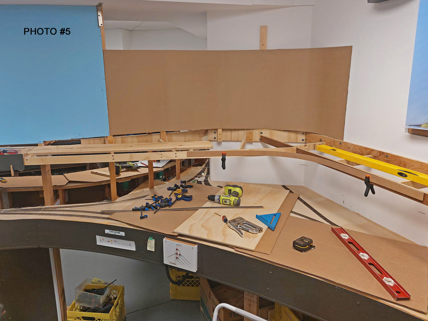
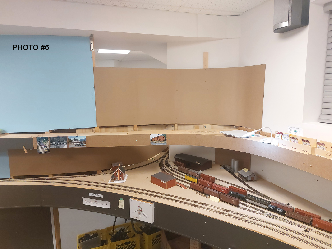
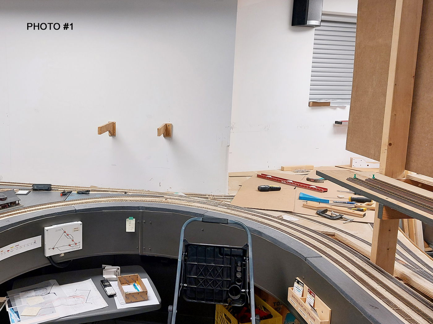
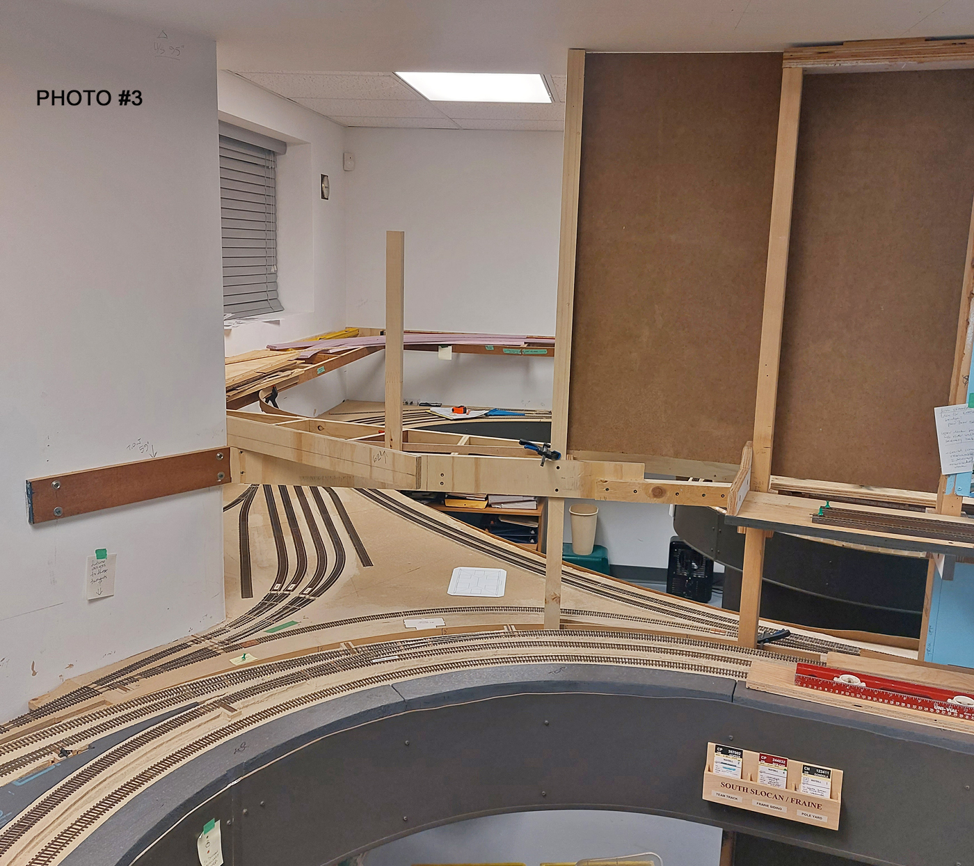
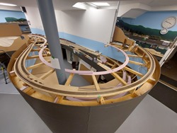
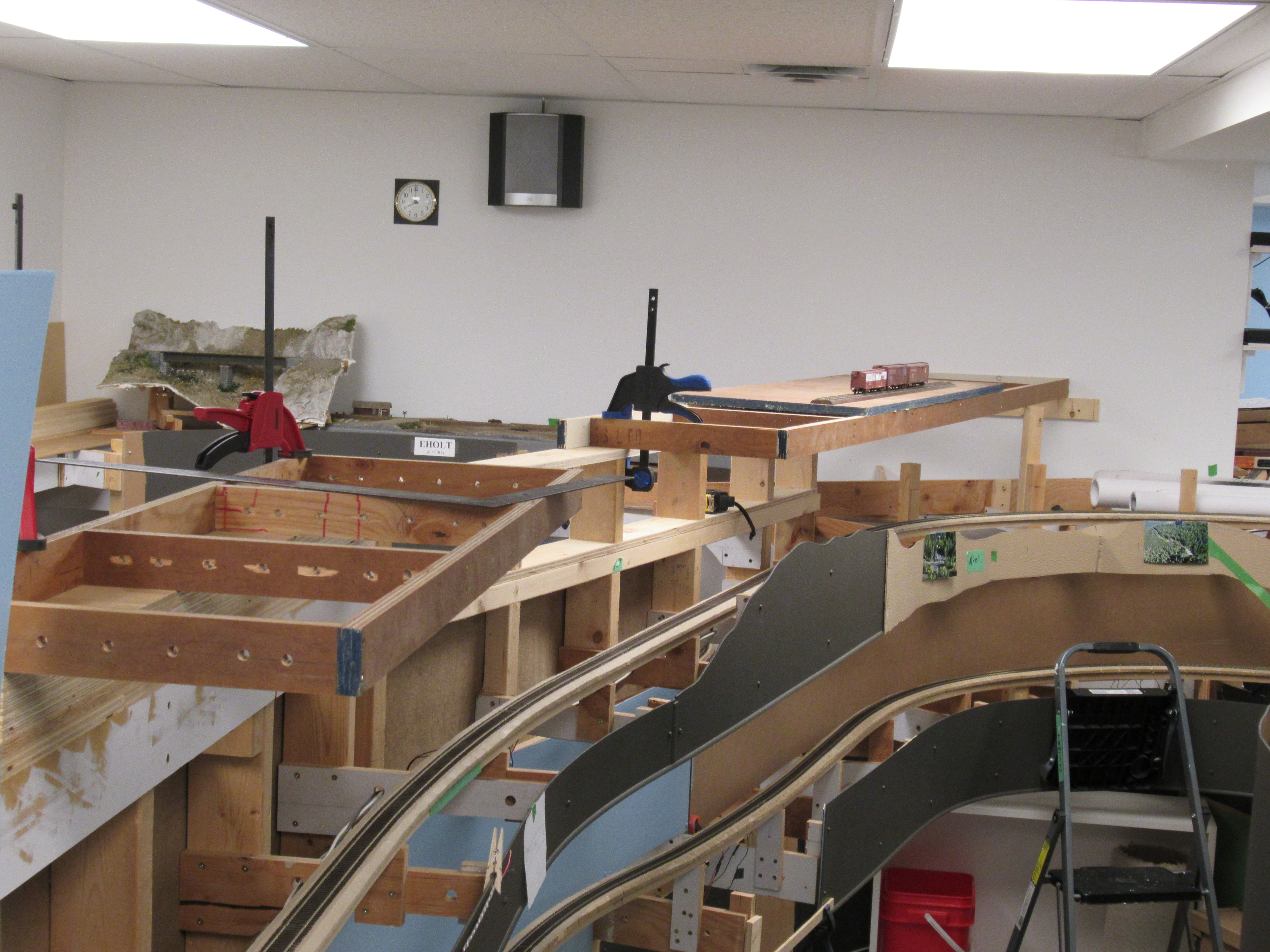
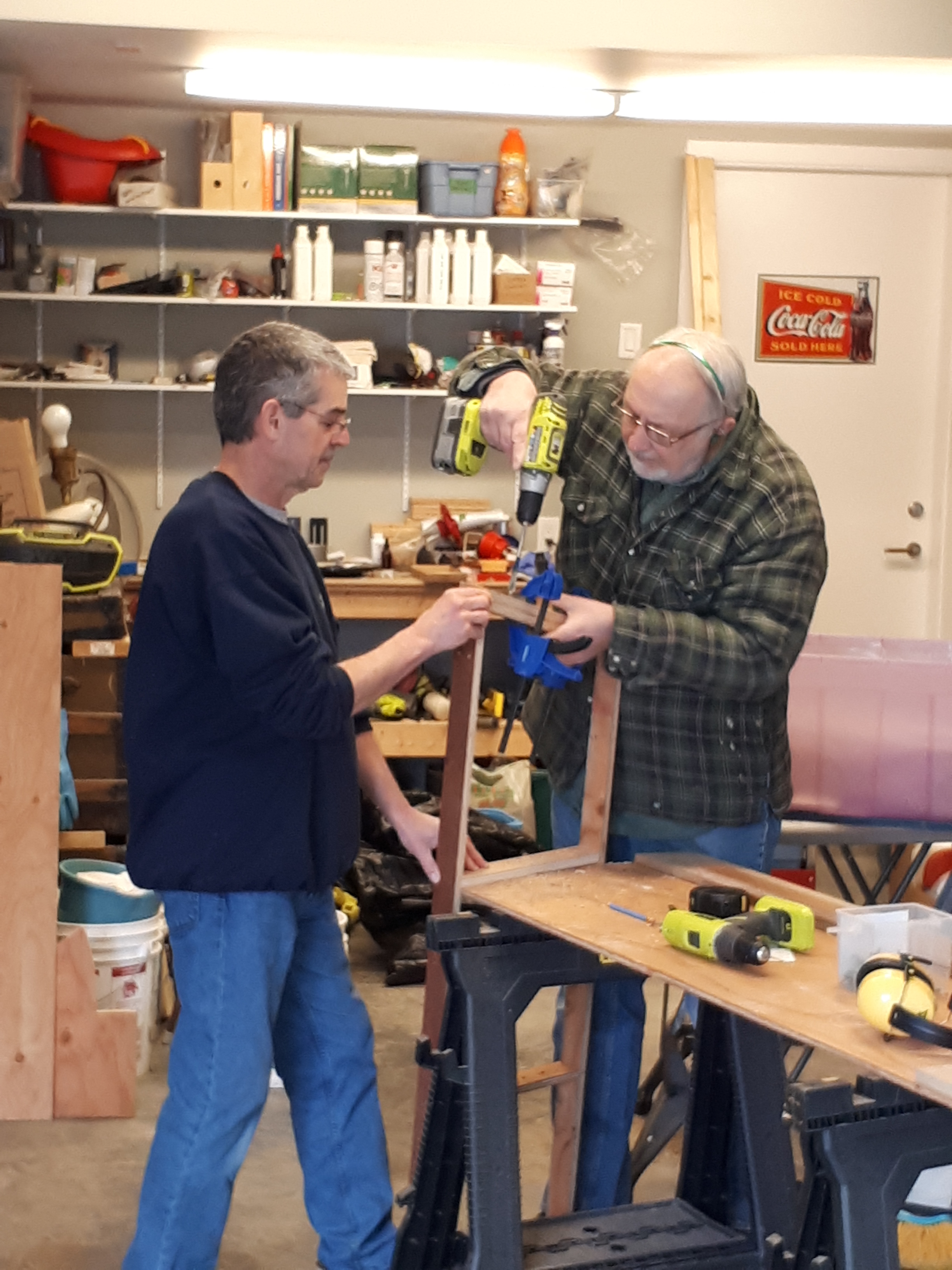
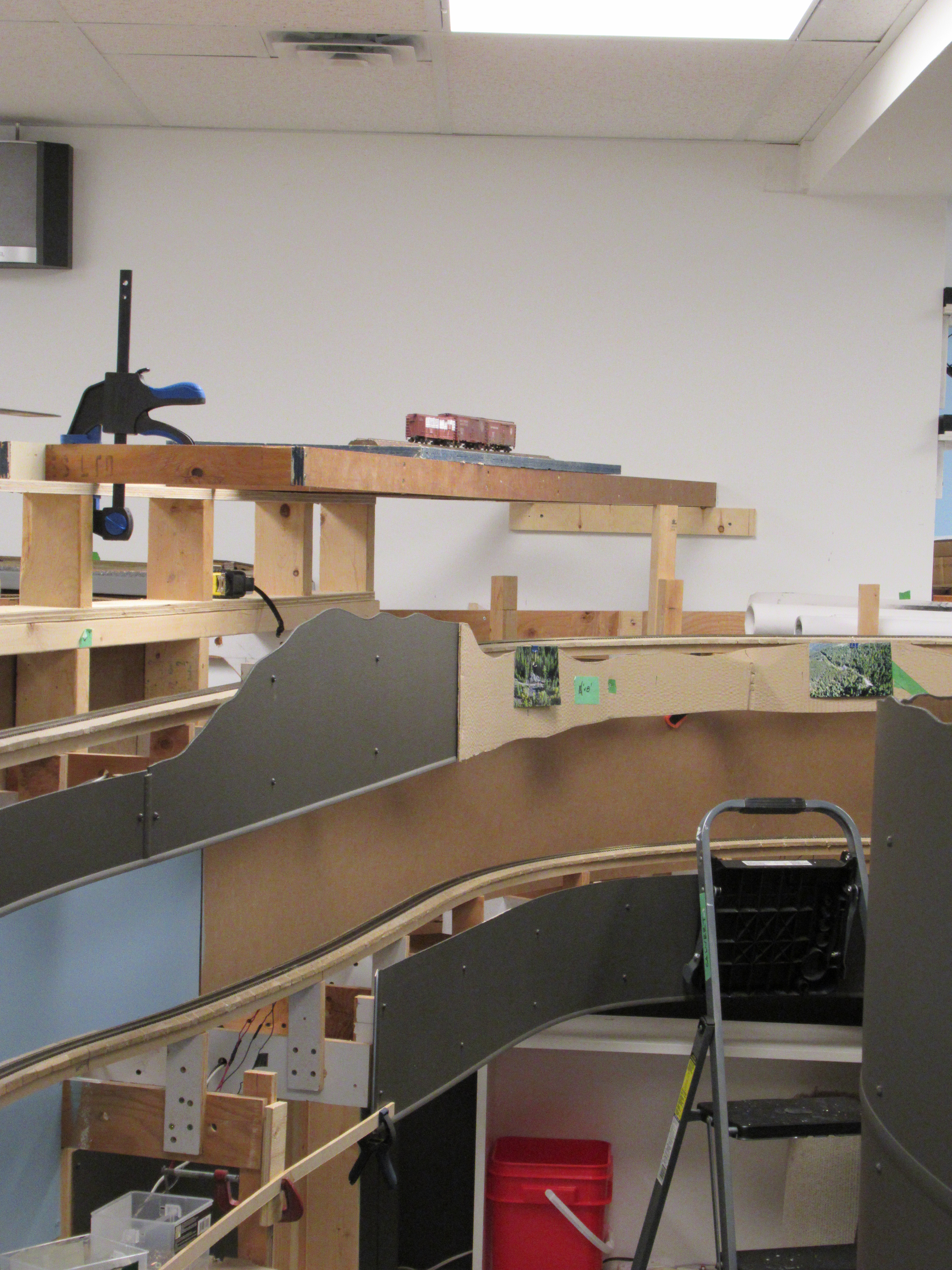
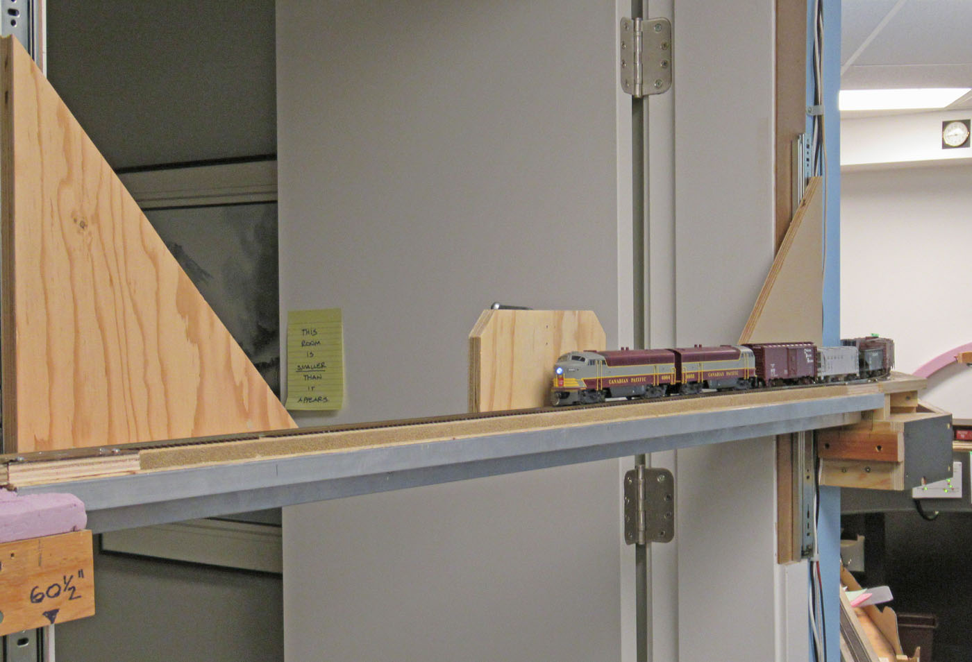
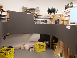
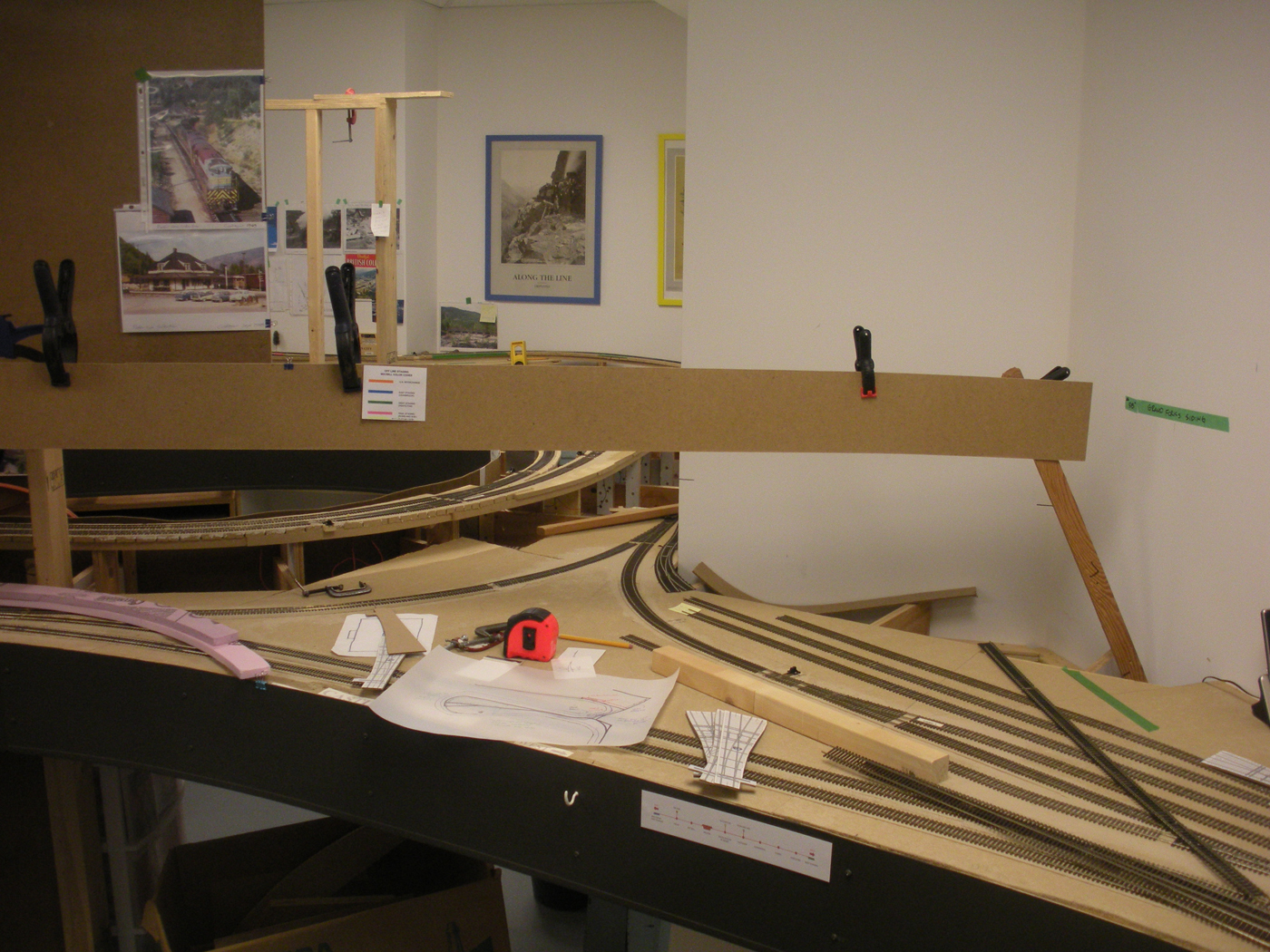
One of the challenges to a multi-deck layout is that it is often analogous to a three dimensional puzzle. This is the case where the South Slocan and Castlegar areas back on to each other on opposite sides of a peninsula. In addition, the track from the Rossland staging yard emerges into Castlegar at this same location. There is also some consideration required for the future upper deck areas that mirror the geometry on the lower deck.
We were also beginning to plan the scenic landforms for the areas in, and around South Slocan which are also affected by physical geometry of this entire area.
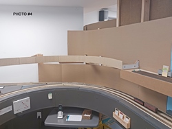
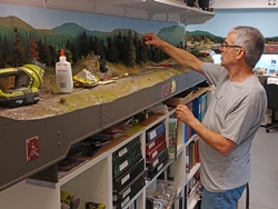
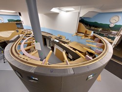
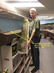
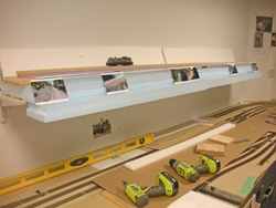
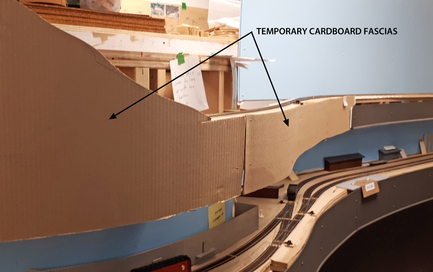
So, like many challenges faced during the construction of the layout, it was decided that some mock up framing and backdrops would be helpful.
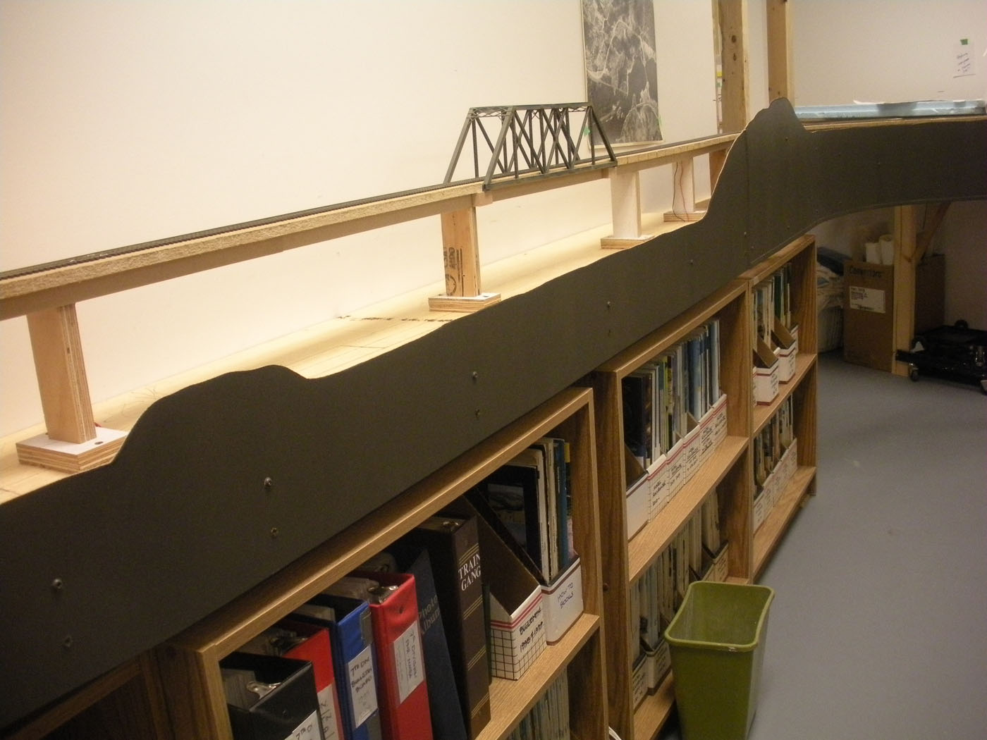
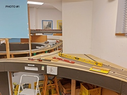
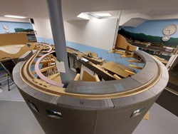
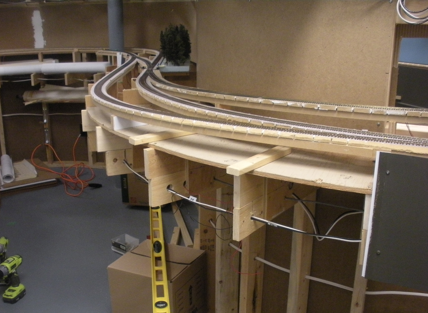
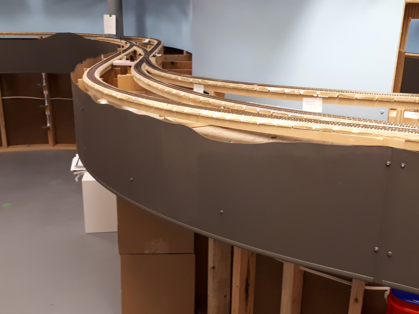
Following below are a series of progressive photos just to provide a visual of what we accomplished. It was not pretty, but it is impactful.
Here is the Castlegar side;
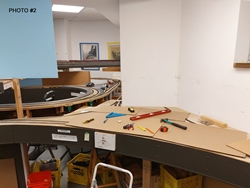
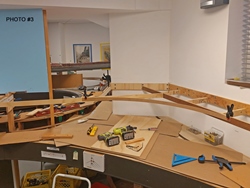
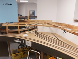
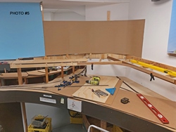

Here is the South Slocan side;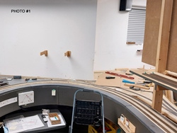
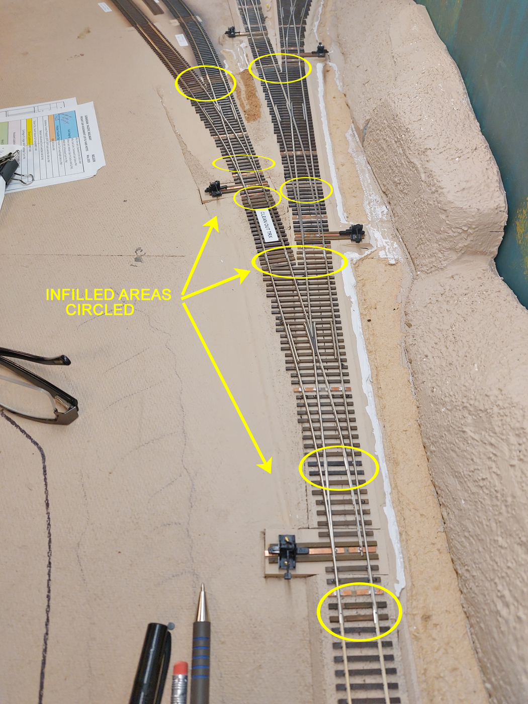
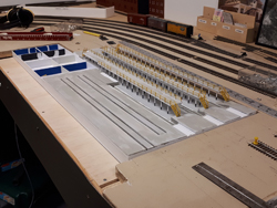
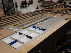
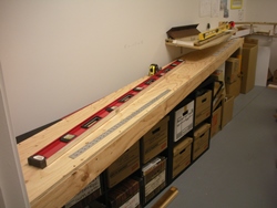
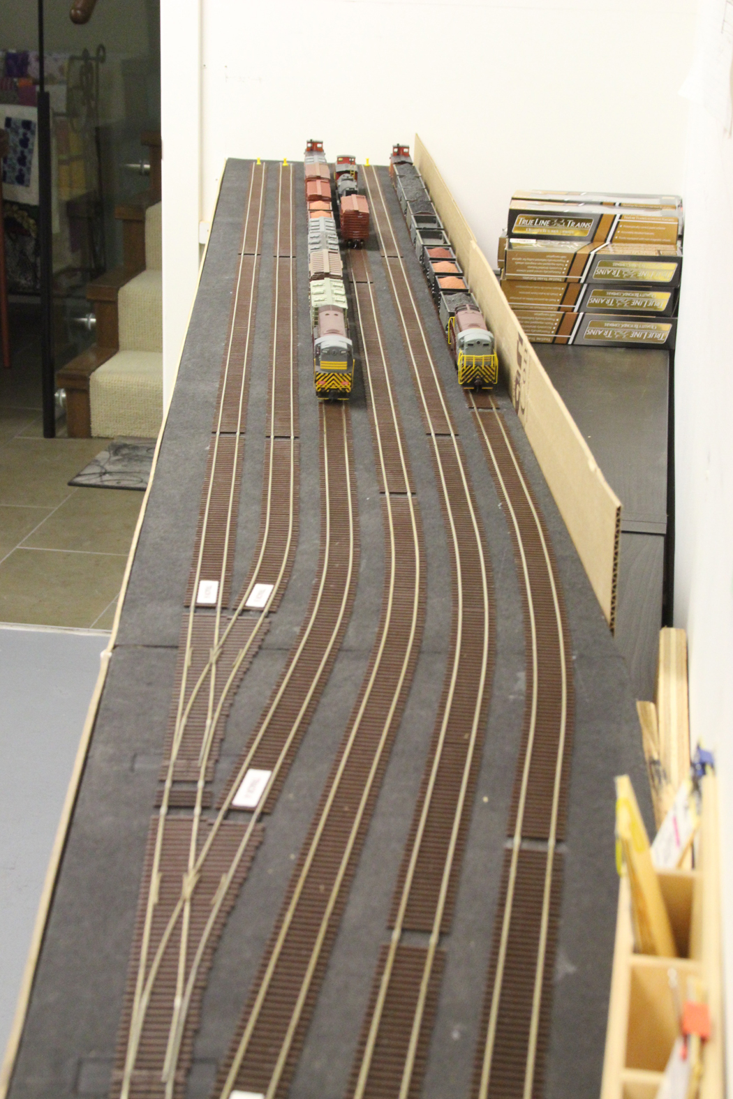
October 2023 | CPR Boundary Subtie infilling; nelson yard
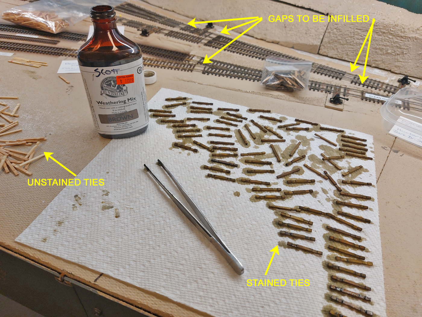
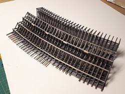
The intent is to keep infilling the gaps in the flex track and commercial turnouts that are used on the layout. I remind myself that I should do this as I install the track, however, I usually “convince” myself that I will get back to it later. Of course, later often is years later!
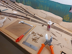
This is one of those small tasks that can be picked away at when short periods of time present themselves. There are two “tasks” that need to be done. The first is to prepare the ties that will be needed and the second is to install the ties.
The infill ties are all commercial wood ties from various manufacturers, some of which are no longer in business. I sand them down to various thicknesses and create notches in them to allow them to slide beneath rail joiners, while keeping the upper surfaces in the same plane as the adjacent plastic ties. I am also fortunate to have some longer “switch” ties that a friend milled down in thickness to suit some different conditions. These are cut to length to suit specific requirements.
These ties are all stained or painted to sort of match the color of the surrounding plastic ties. All the track gets airbrushed later, so the initial color needn’t be too accurate. It’s just to diminish the visual disparity that would exist if the infill ties were not colored.
Here are some progress photos;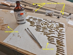

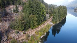
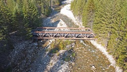
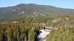
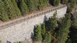
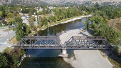
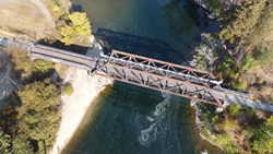
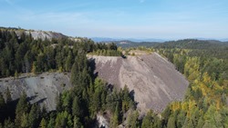
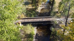
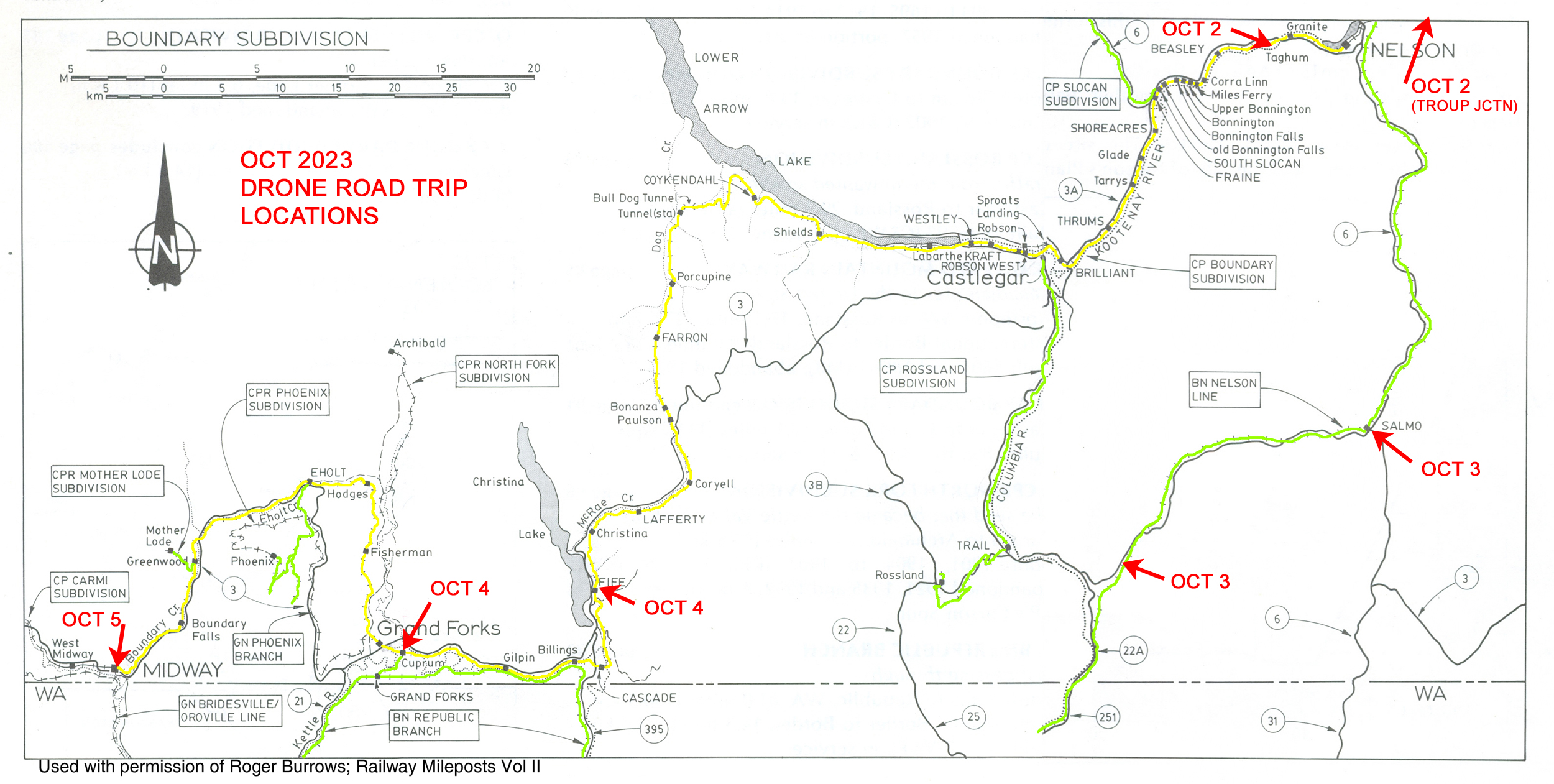
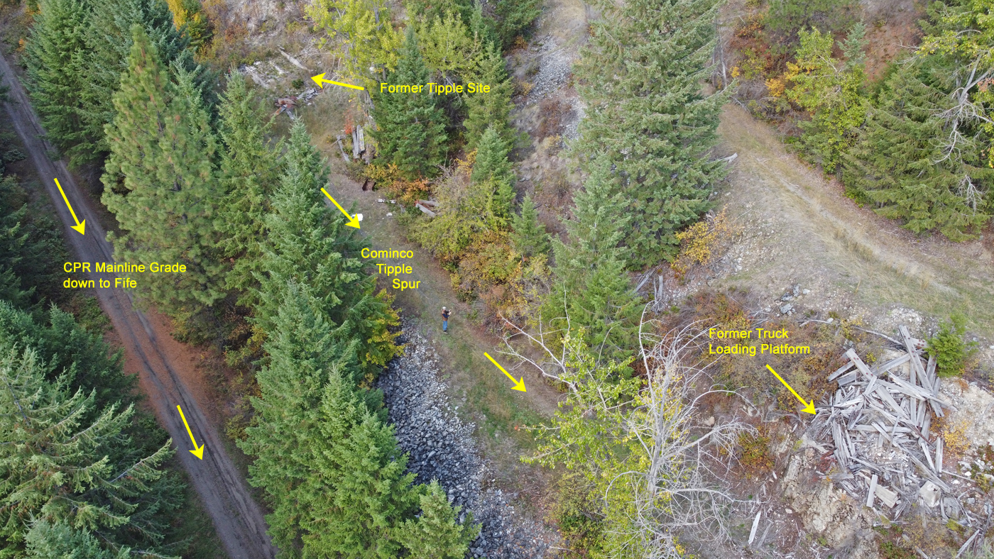
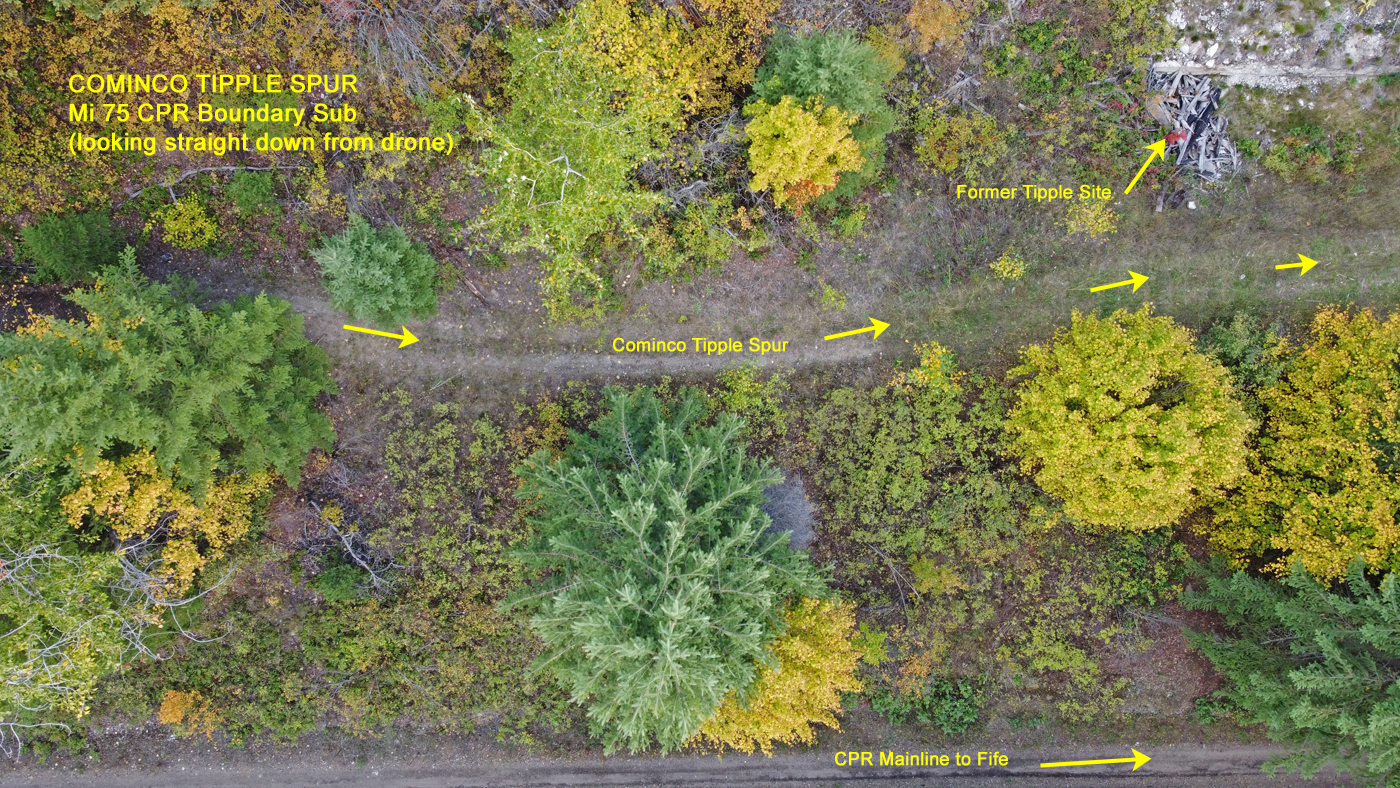
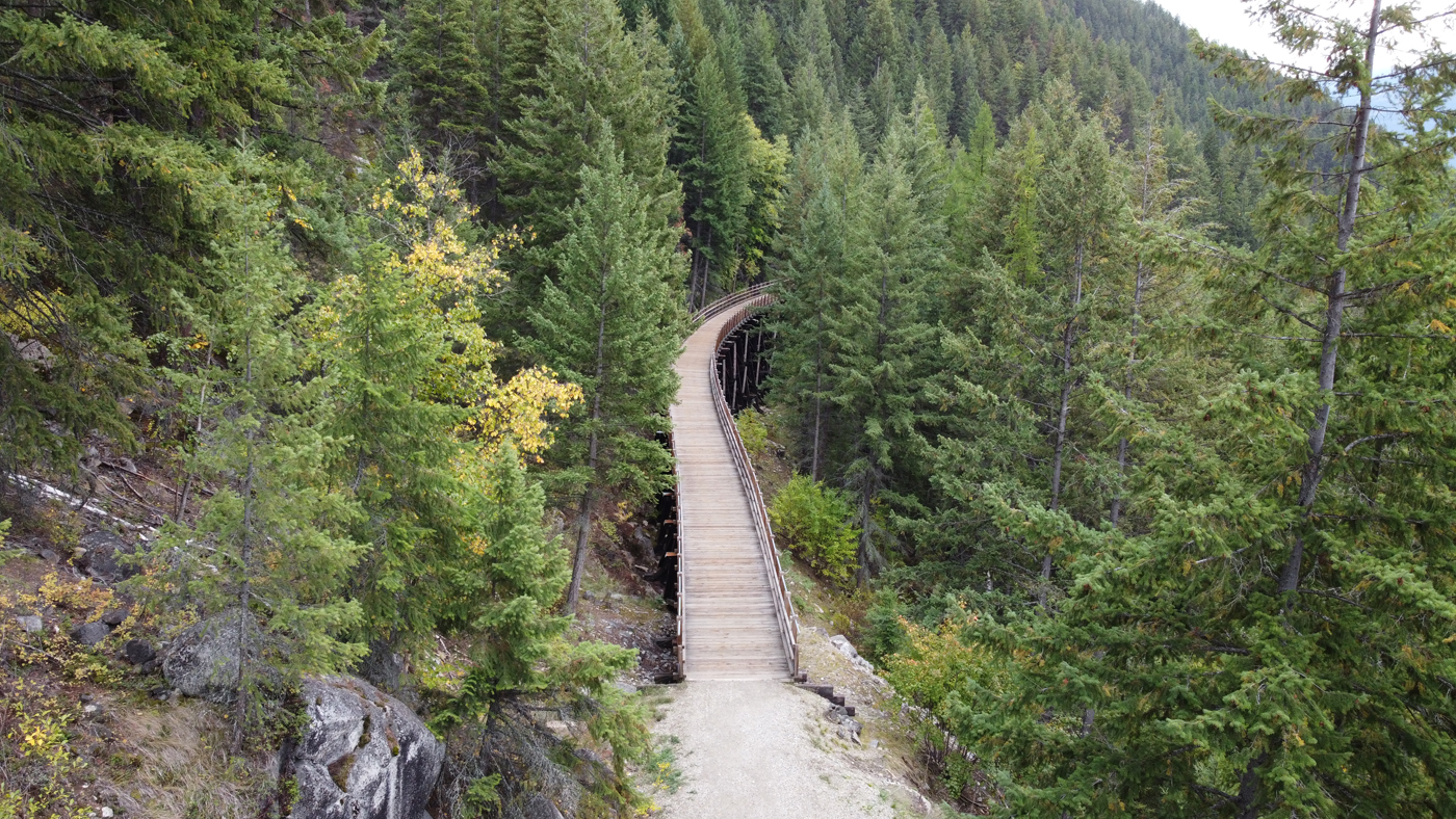
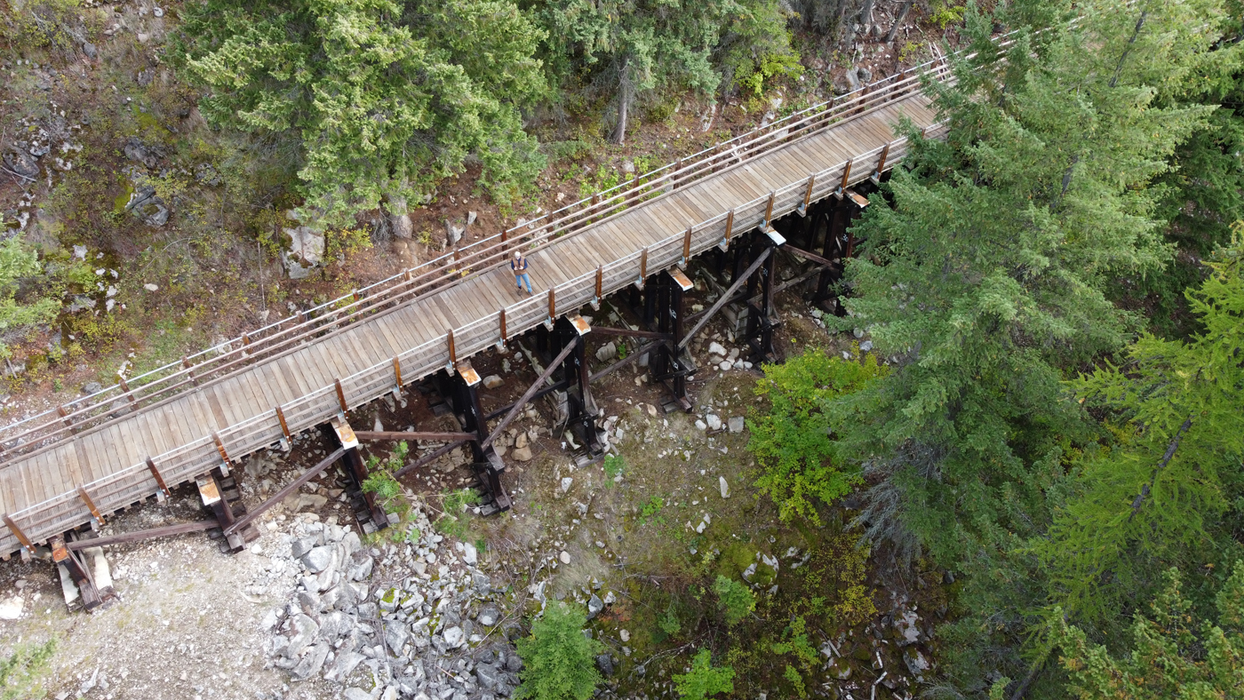
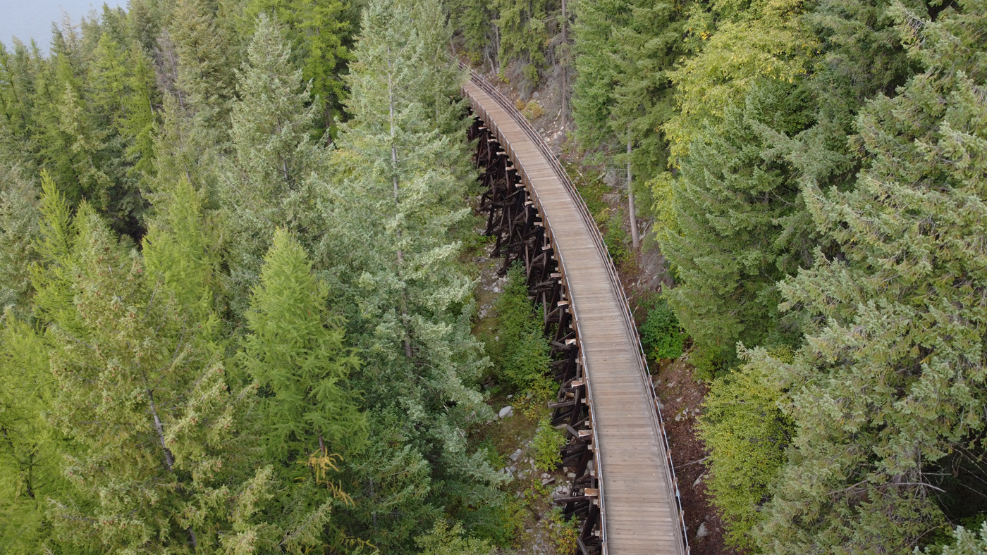
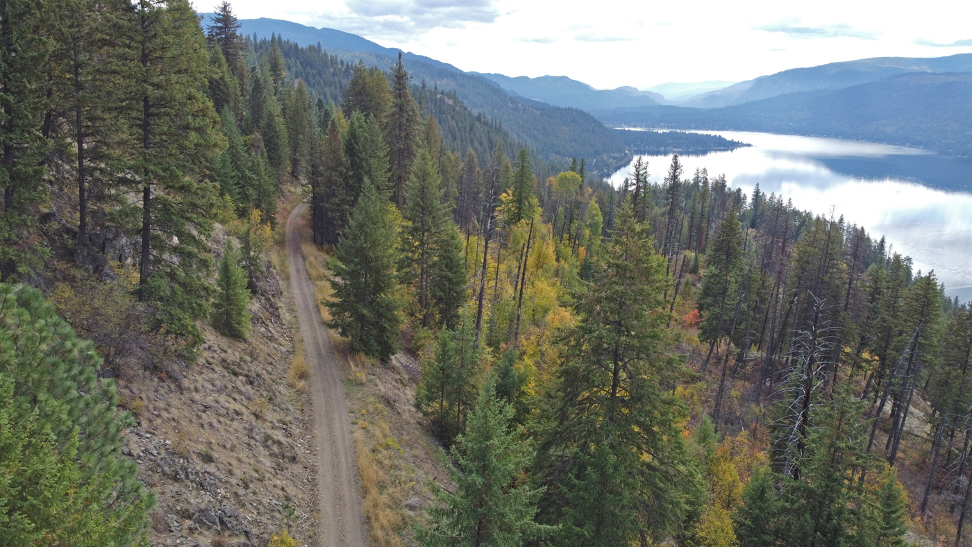
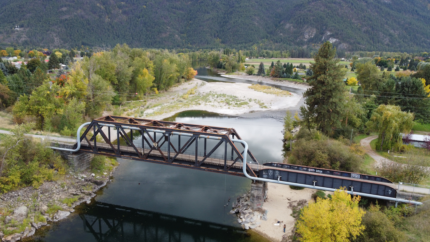
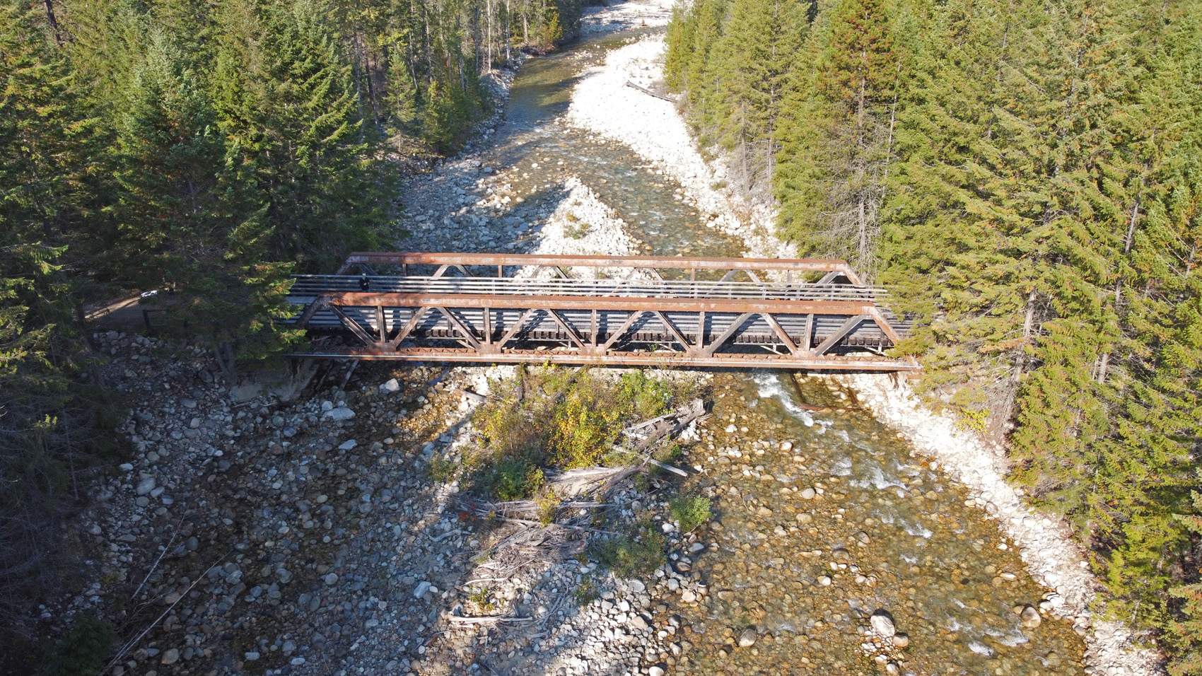
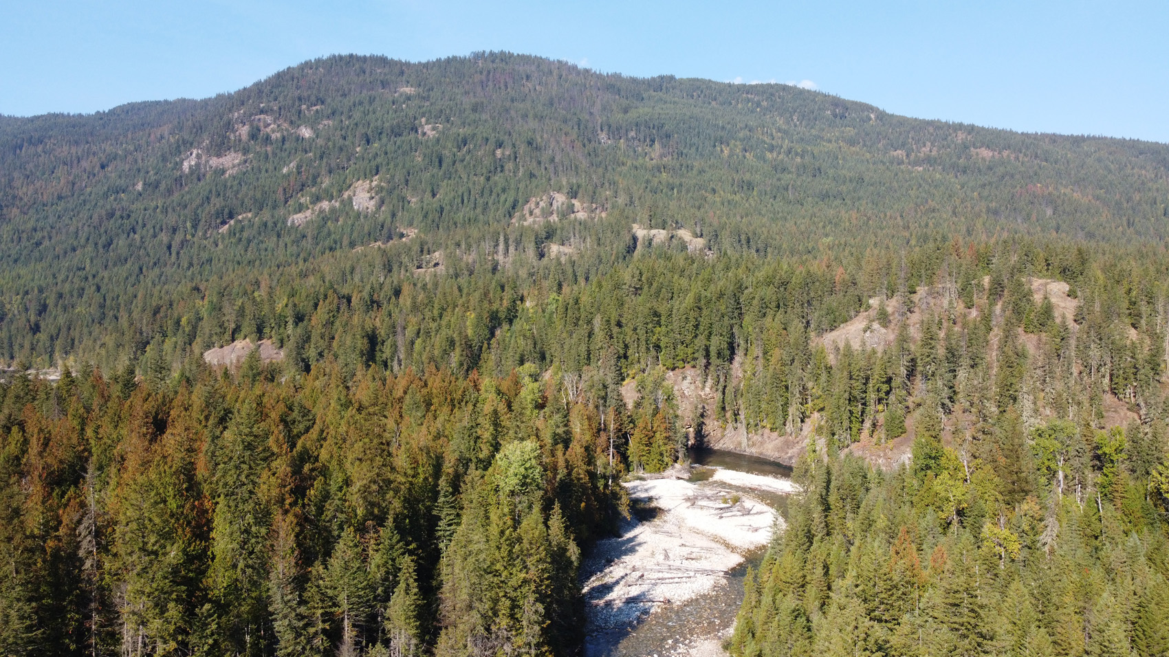
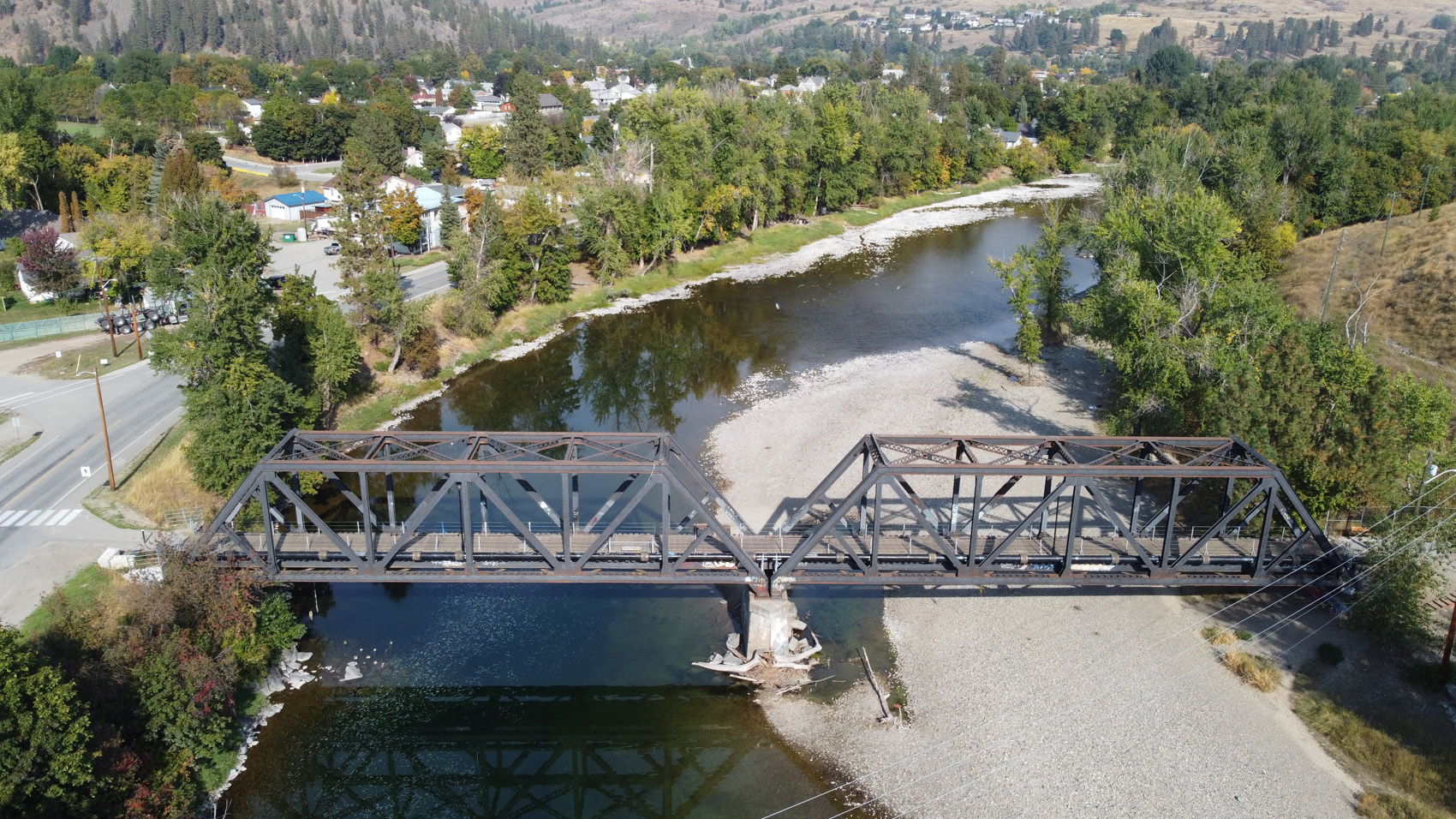
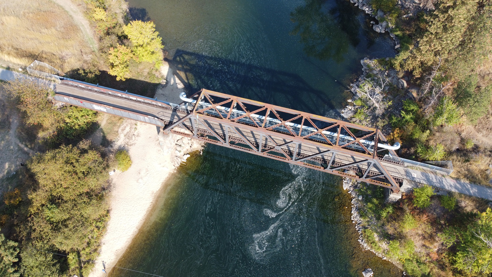
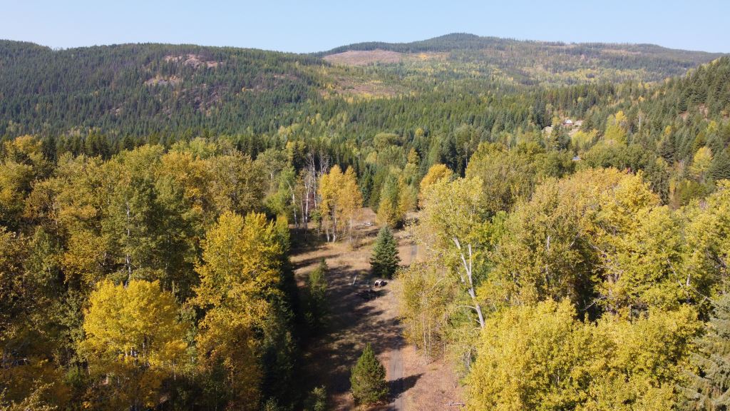
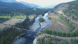
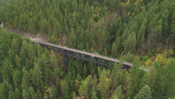
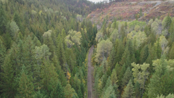
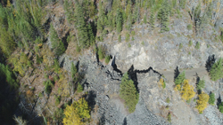
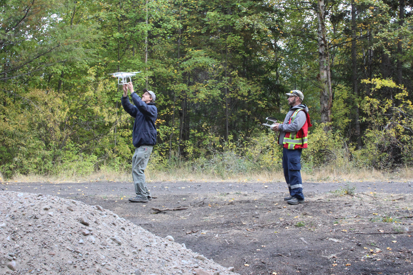
October 2023 | CPR Boundary SubDrone Research trip
In early October, I headed off on my fourth drone research trip covering the areas that I model. This was the third time I used my own drone. The extra batteries I purchased last year proved indispensable this trip due to the heavy winds I encountered at some locations.
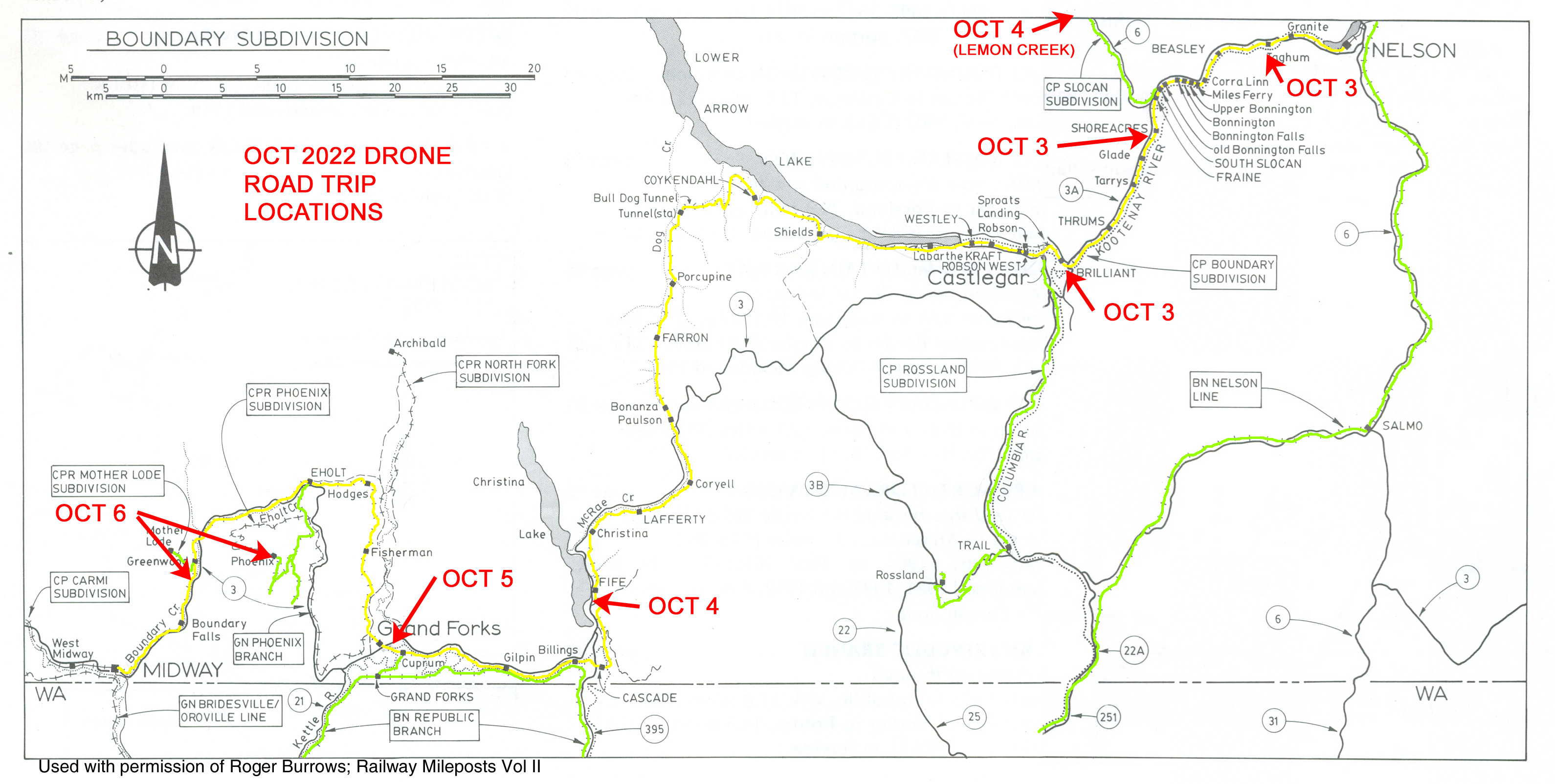
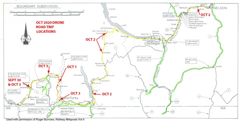
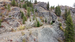
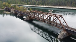
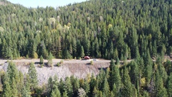
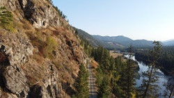
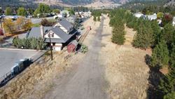
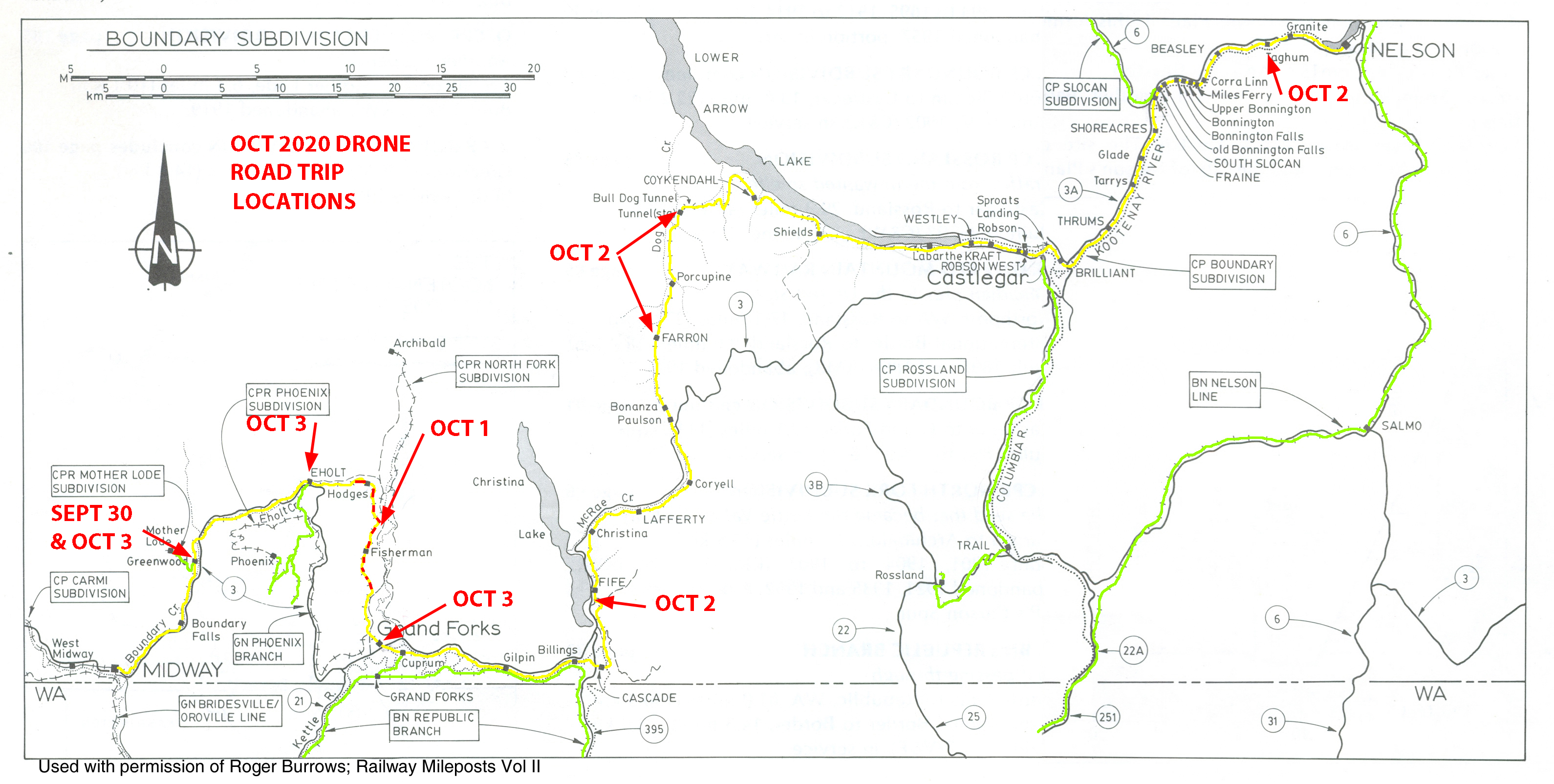
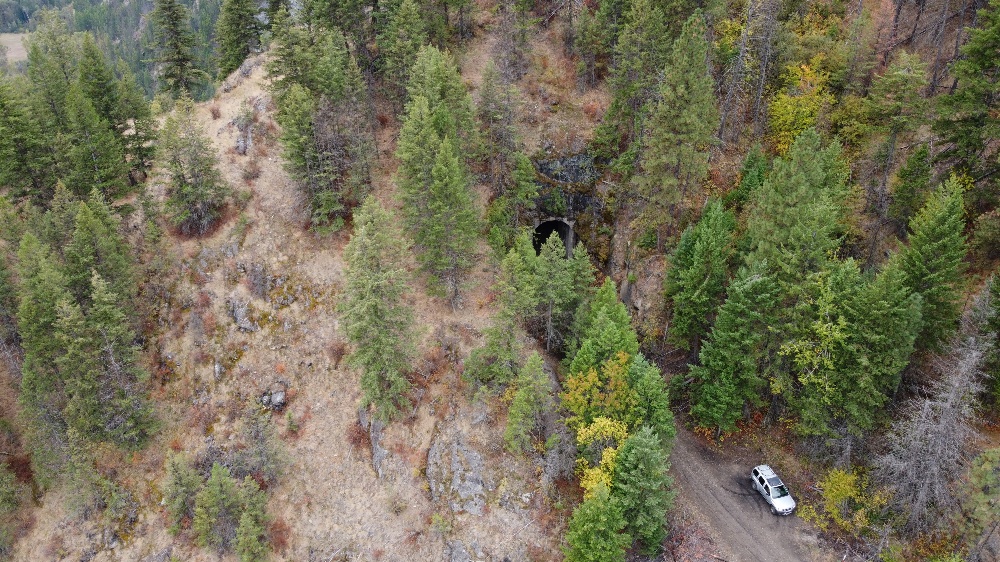
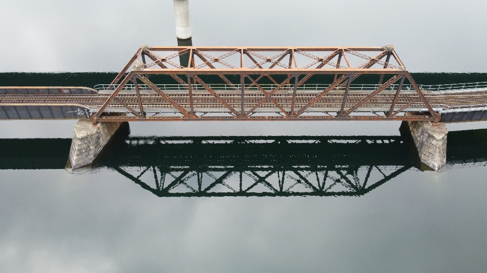
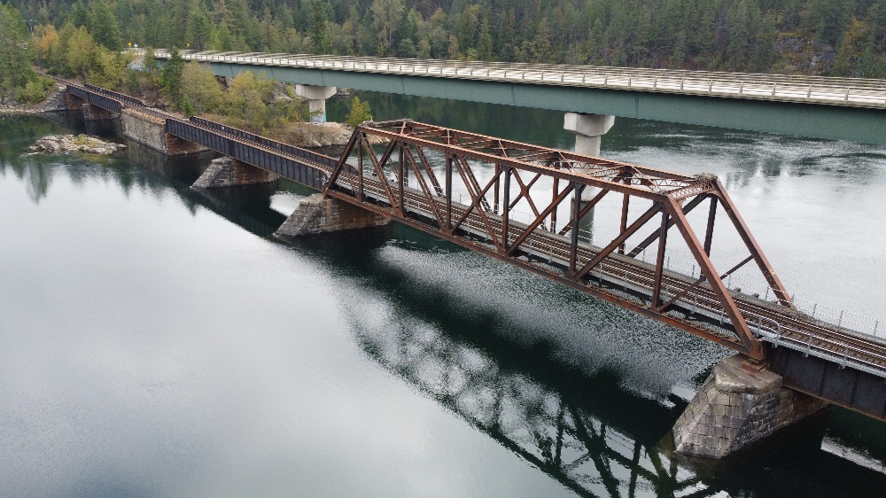
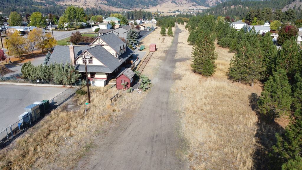
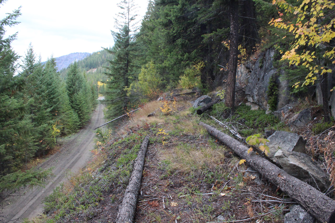
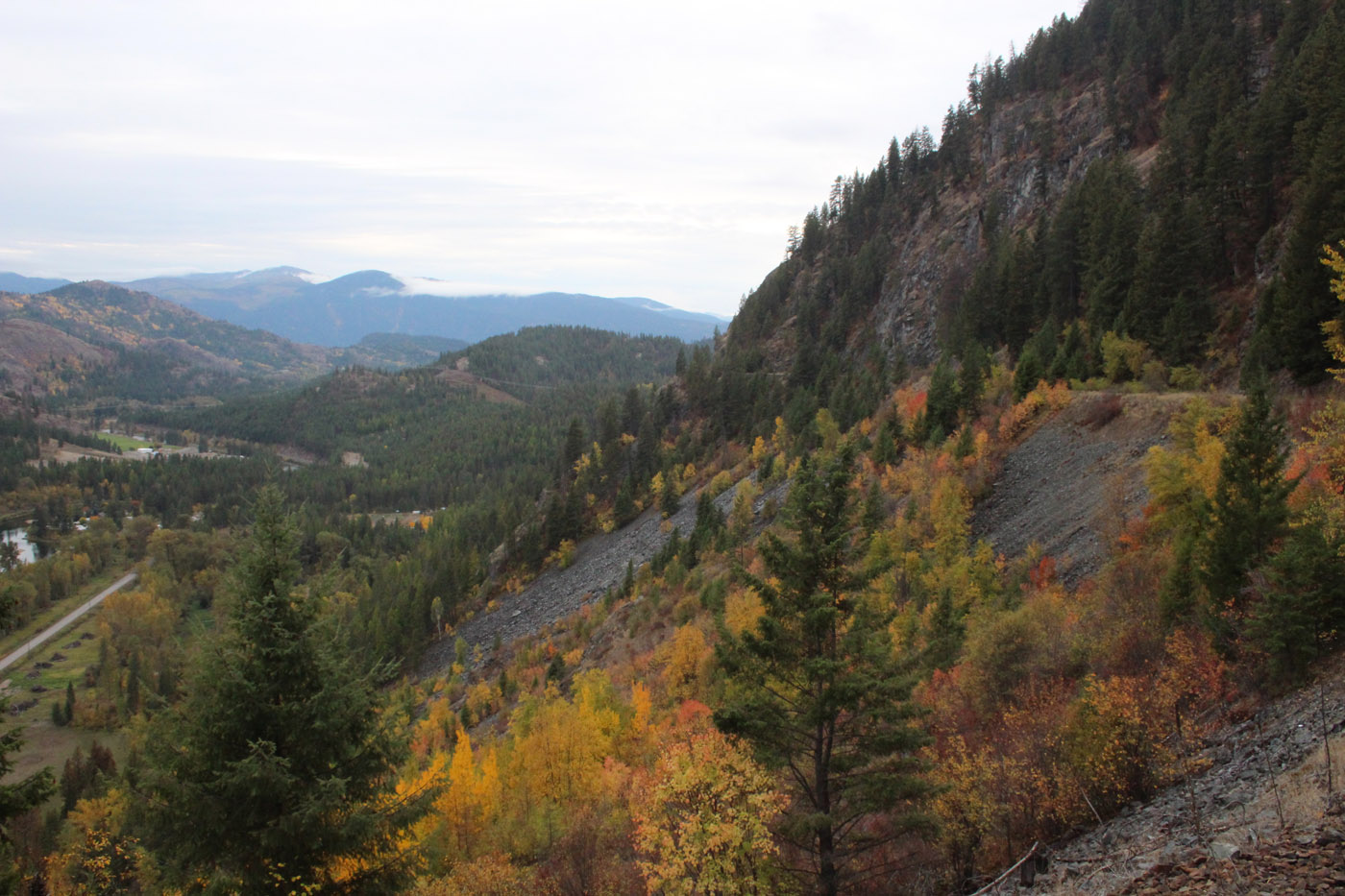
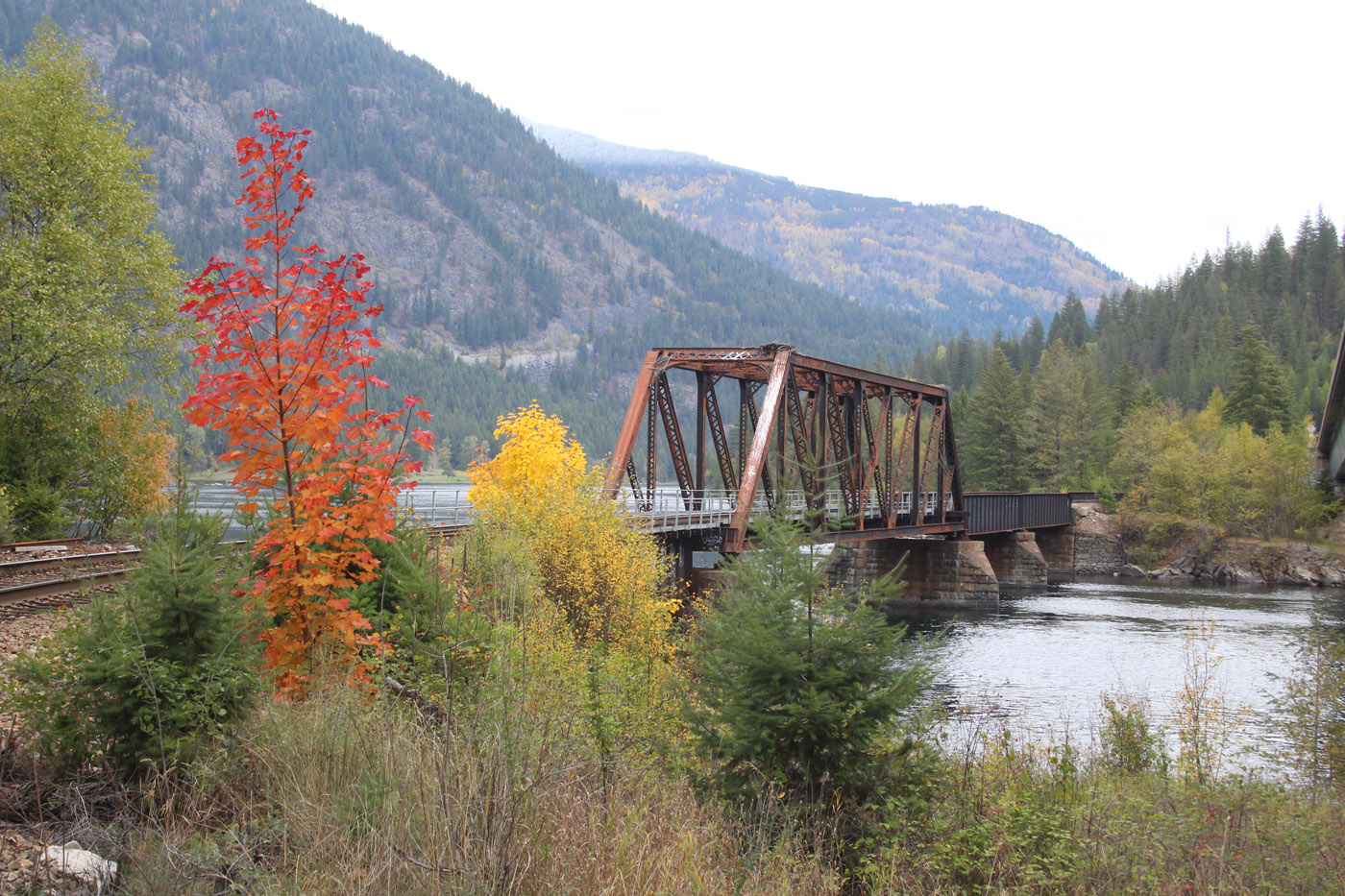
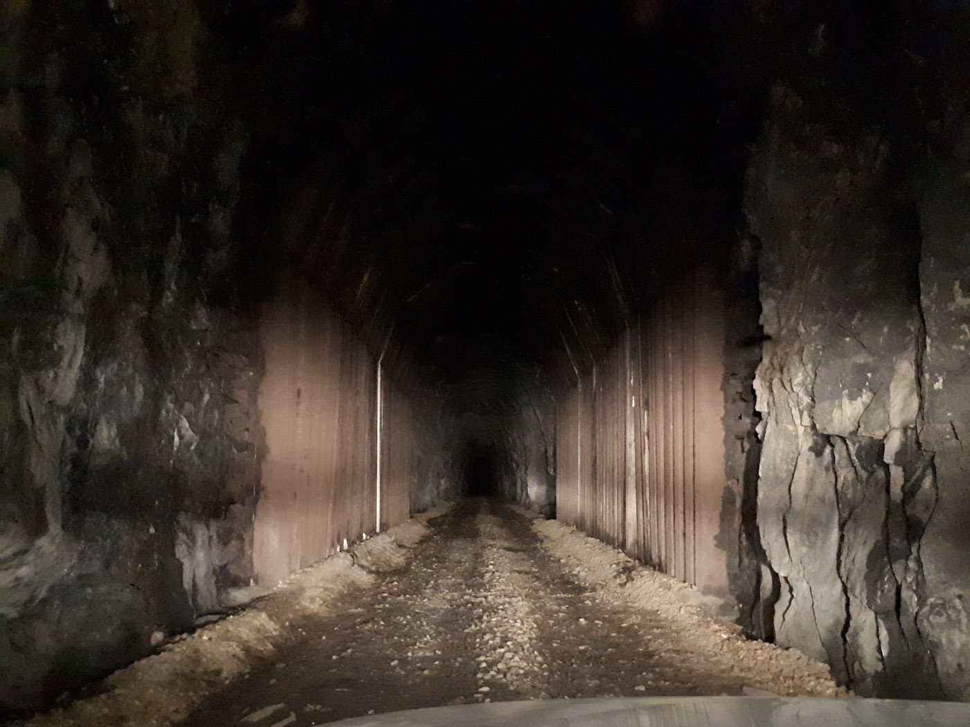
Prior to the trip, I marked up a map of the Boundary Sub area with potential locations and what I wanted to capture. I then developed a travel plan that spanned five days and covered a couple thousand kilometers. On this trip I was able to remain on public roads and did not need to drive onto the abandoned grades as I have done in the past. I also did a lot more ground level photography with my SLR camera due to airport flight path restrictions in some locations.
As noted in my previous posts concerning the use of drones, I am very careful where I fly, and I obtain permission where appropriate to do so.
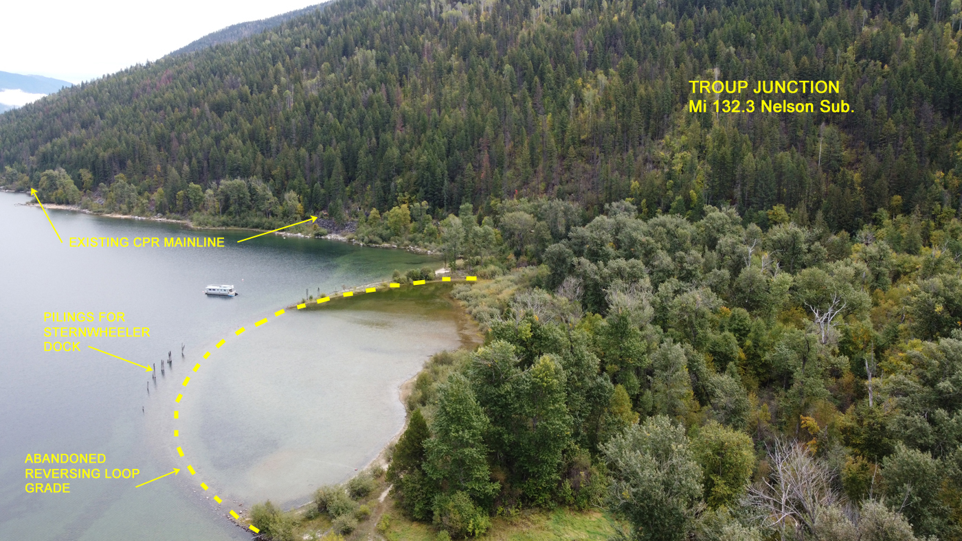
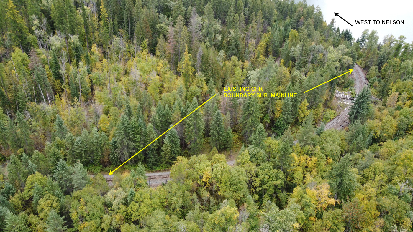
Here is a map of the Boundary Sub with the locations where I did photography noted on it.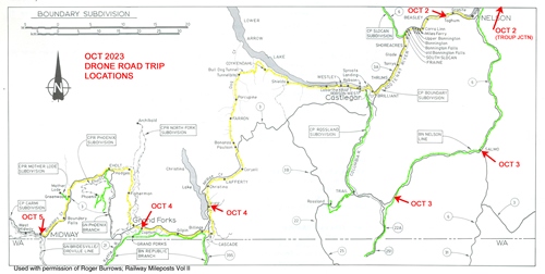
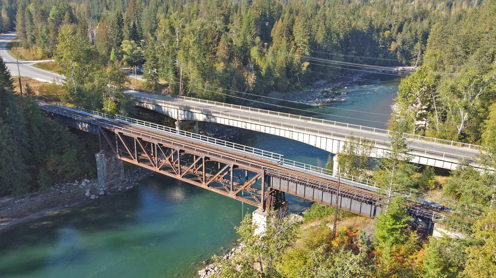
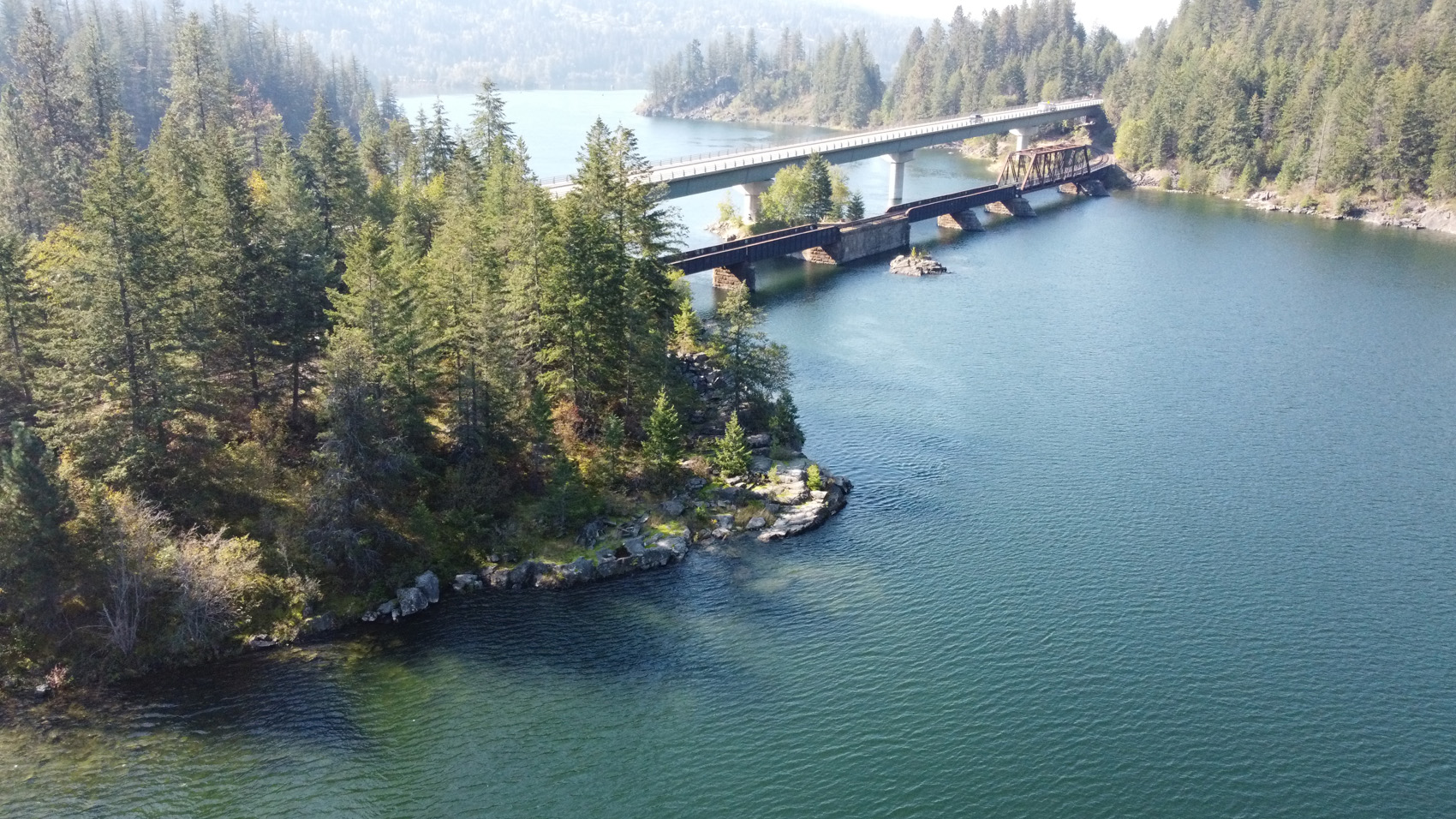
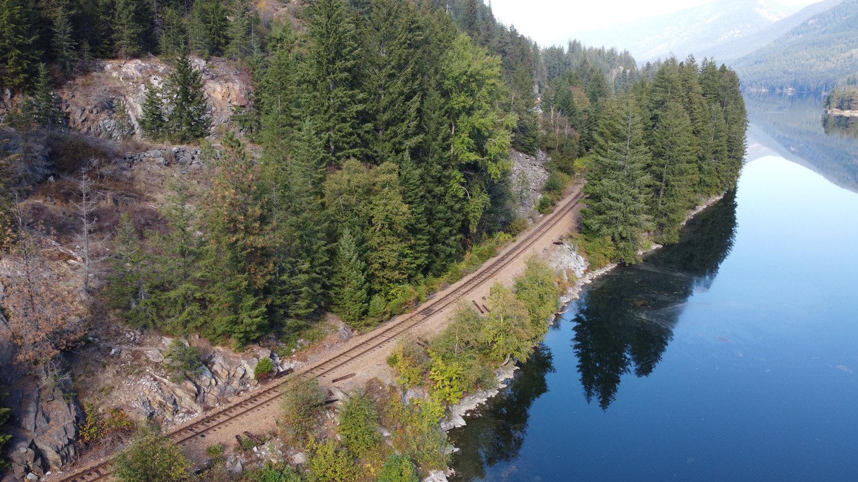
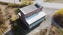
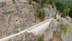
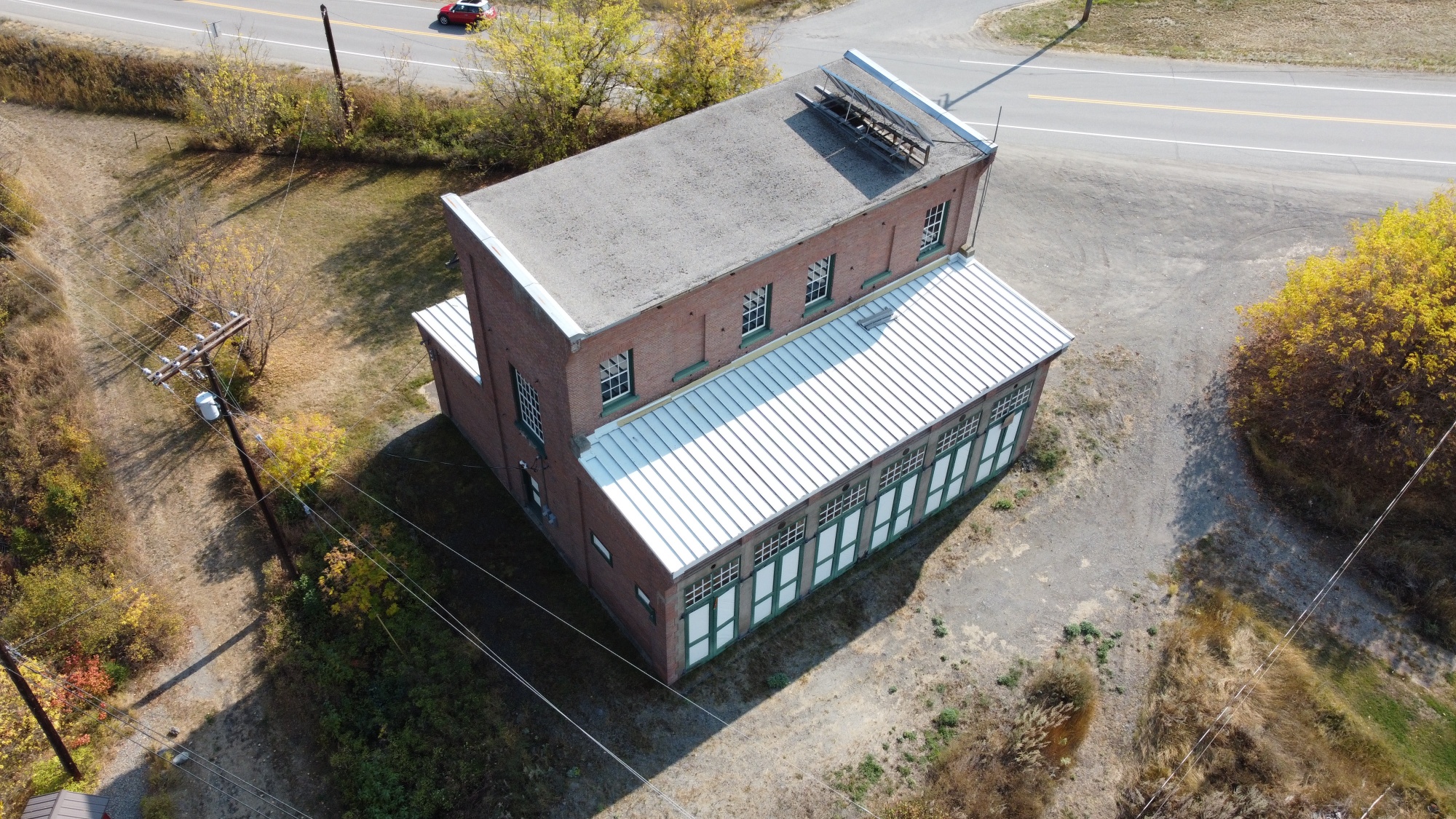
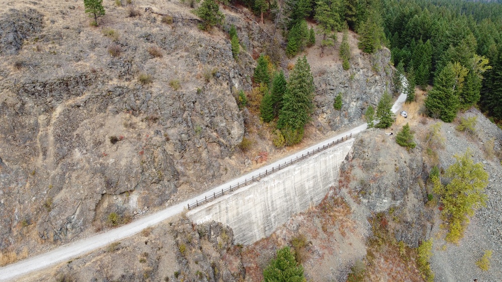
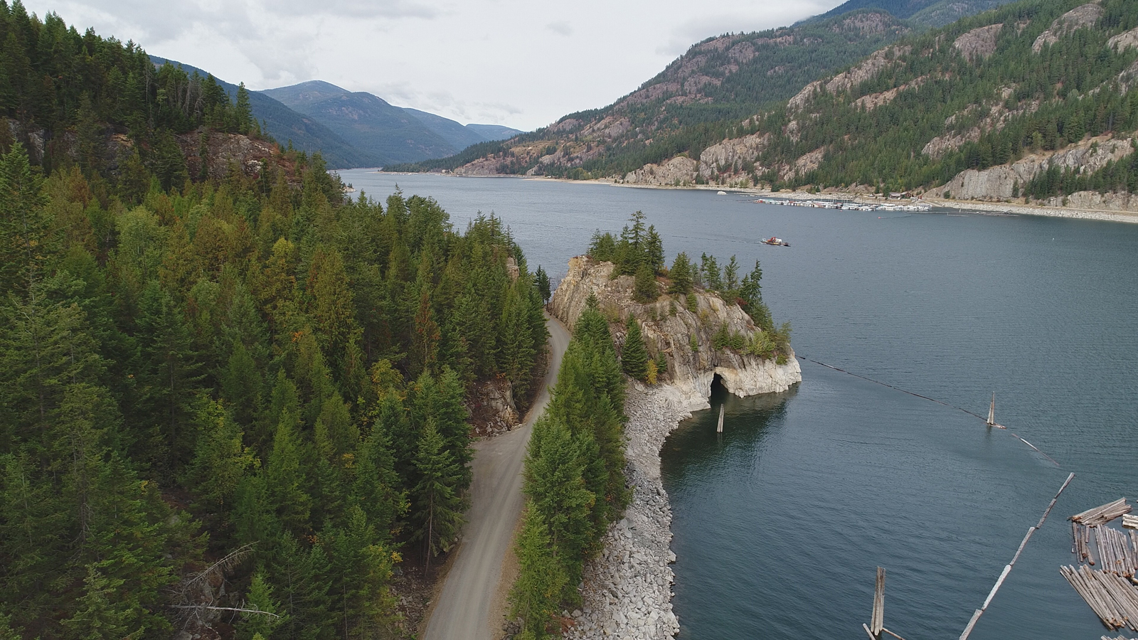
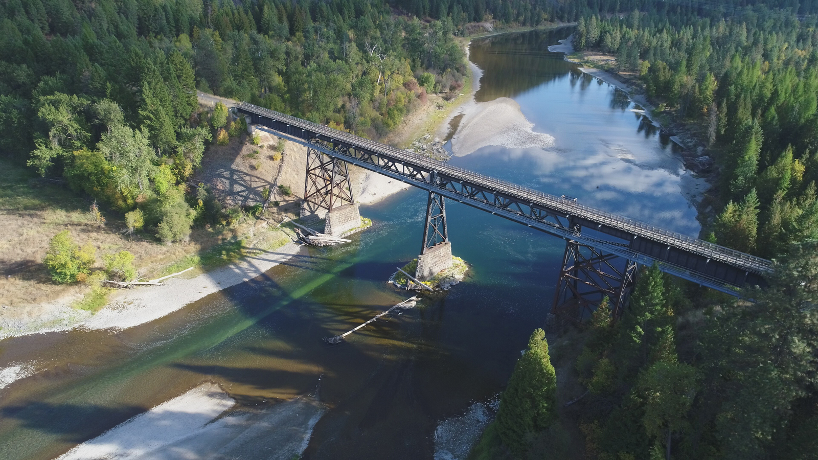
Below is a sample of some of the still photos taken. The videos are too large to include here.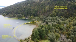
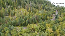
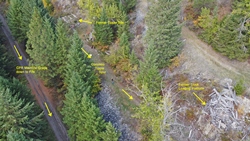
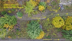
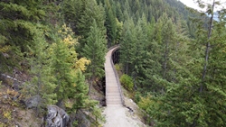
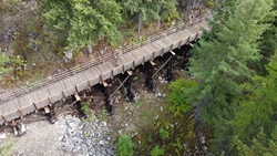
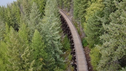
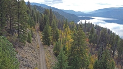
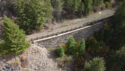
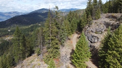
You can view more of my drone photos in the Prototype Photos section of the web site.
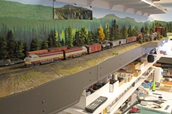
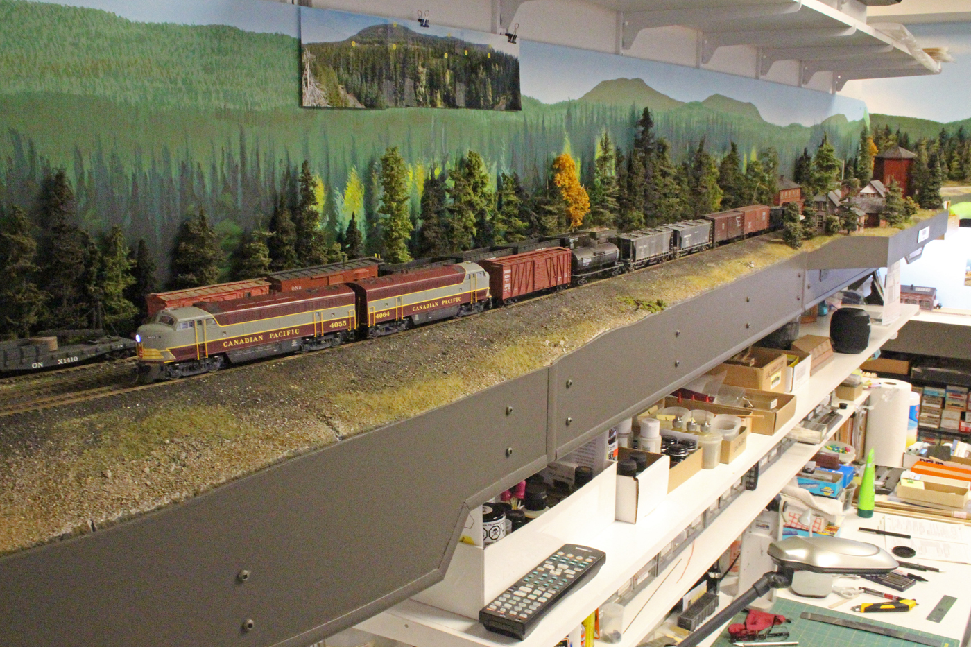
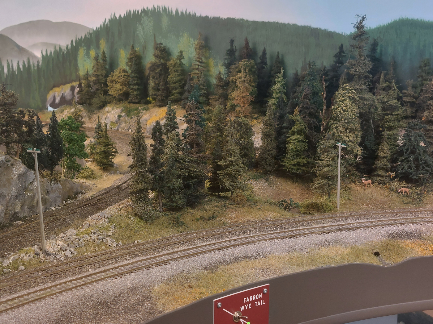
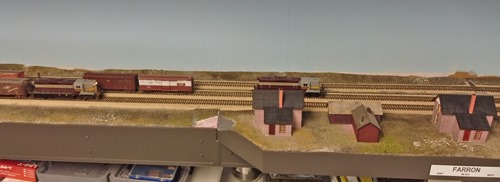
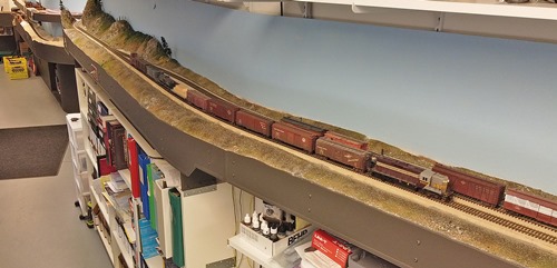
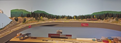
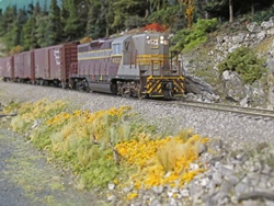
August & September 2023 | CPR Boundary SubFarron foliage work
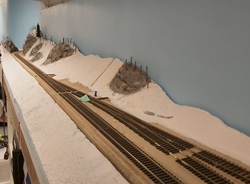
The Fall 2020/Summer 2021 post showed the progress of the Farron siding shelf area of the layout. While the work was nowhere near complete, it looked much better than the white plaster landforms.
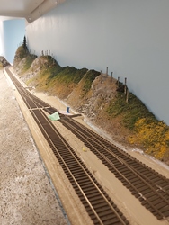
Over the balance of 2021 through to early 2023 we continued progressively working on the scenery and structure installation in this area of the layout. The 24 foot long backdrop was completed in July 2022 by Rene based on my drone photos of the area.
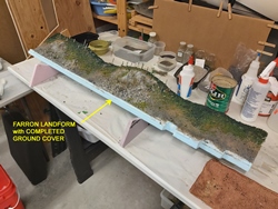
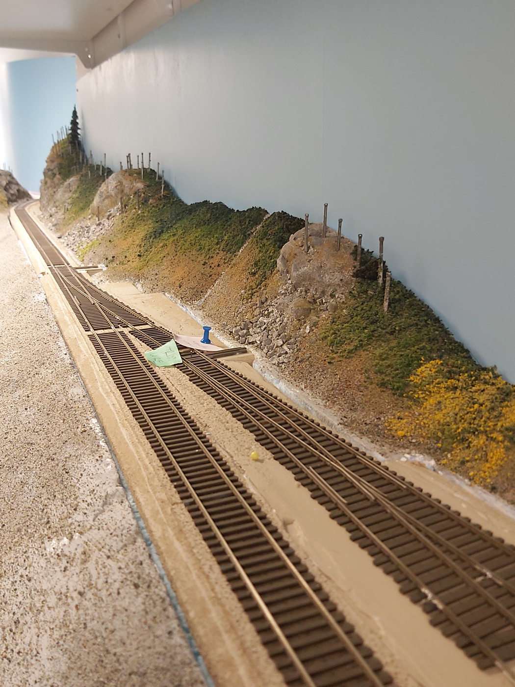
Once satisfied with the backdrop and ground cover, it was now time to “finish” this section of the layout by completing ballasting, adding static grass, planting trees and other foliage.
Here are some progress photos, starting with the most recent and traveling back in time.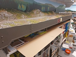


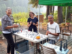
August 2023 | CPR Boundary Subcabin tree building trip
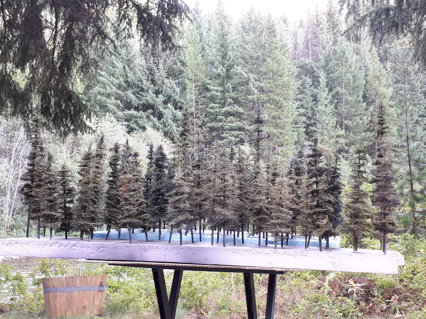
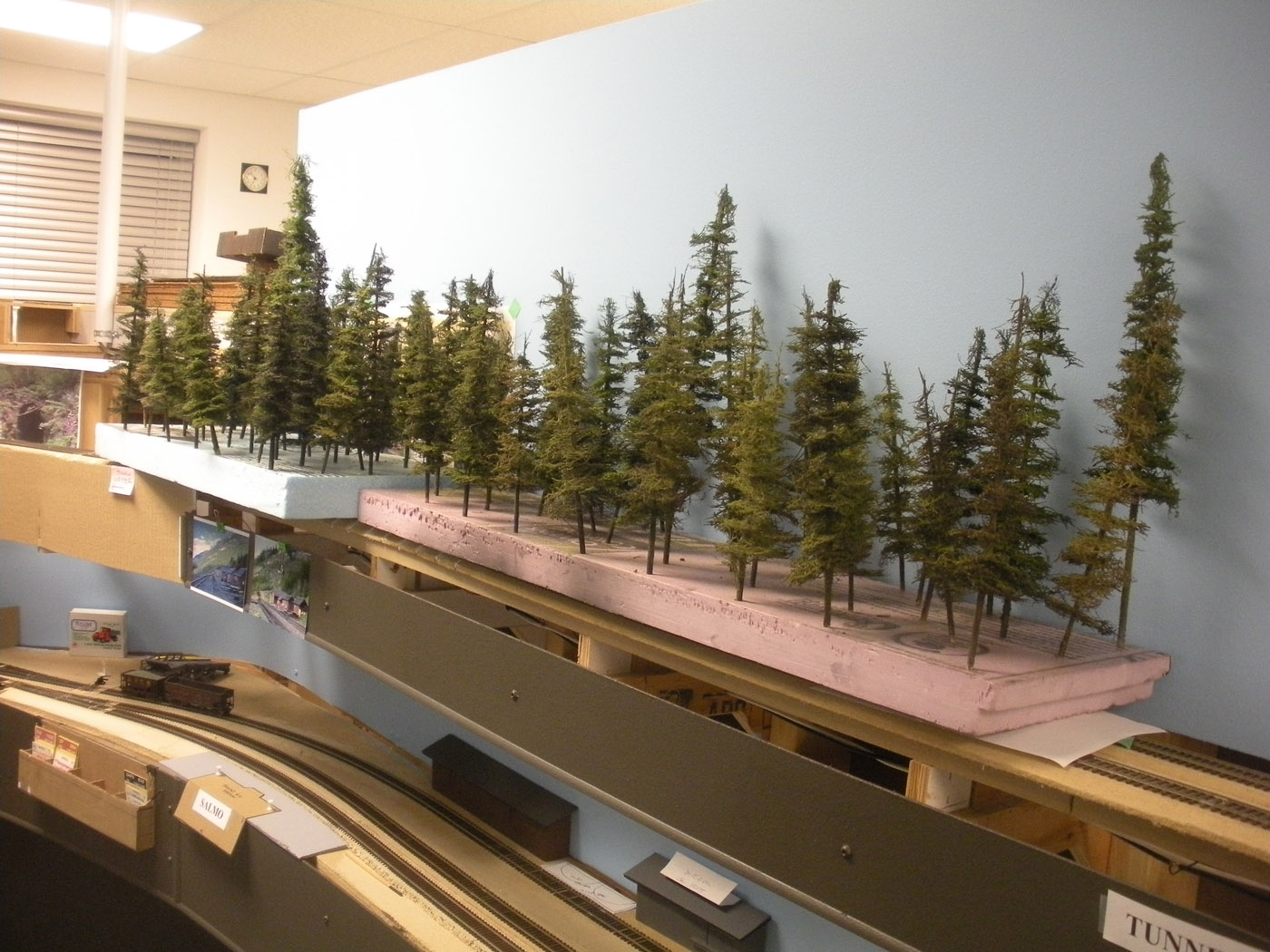
Well, on a layout the size of, and location of the Boundary Sub, there is a need for a lot of trees! Even with the narrow shelf type design utilized along numerous areas, we still need trees, and then – more trees and then – more trees!!
While we have a large inventory of trees, many more are required, so we build some when the urge or opportunity hits us. The 2023 summer presented an opportunity to spend a few days at our cabin in the mountains with our friends; Ken & Patty and collectively built a bunch more trees while we were there. Definitely more enjoyable building them with friends, sitting on the deck looking out over the river on a beautiful summer day.
We do a mixture of furnace filter trees and also use the commercial trees I purchase in bulk from the Philippines. (See also the May 2020 What’s New post).
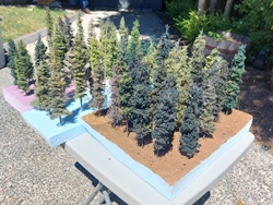
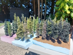
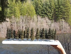
We think these are probably the best furnace filter tress we have even done. We tried very hard to avoid the layered look of some of these type of trees, and utilized probably 20 different color combinations.
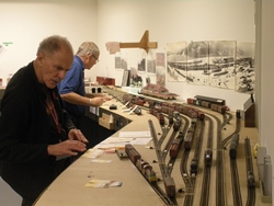
Here are a few photos of the “production line & crew" and some results.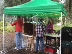
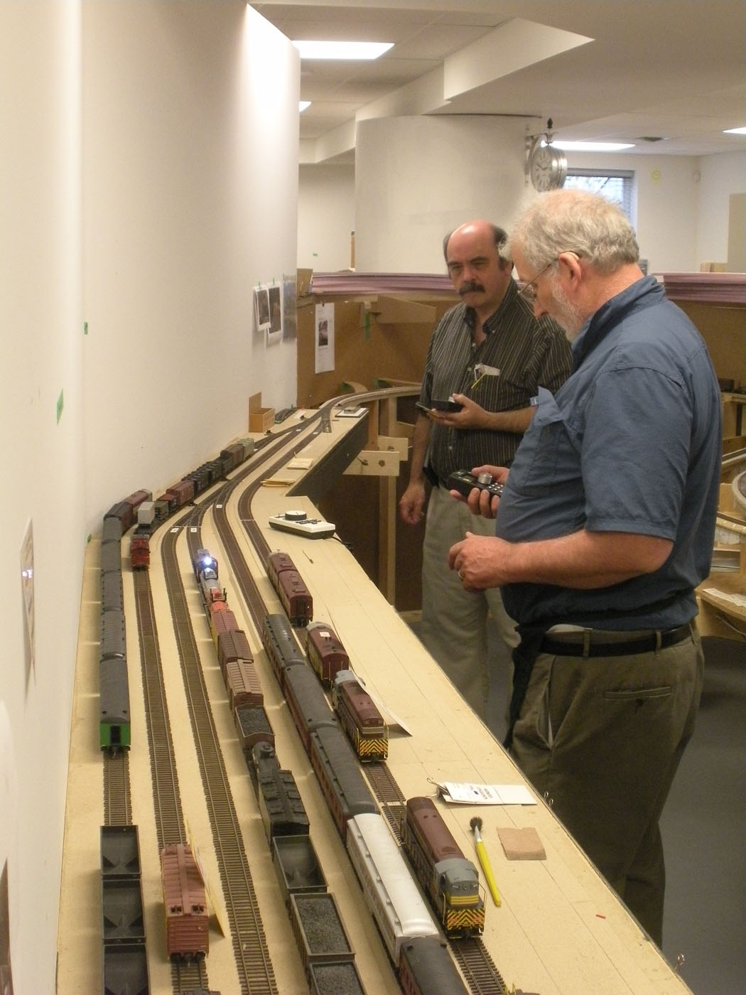
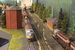
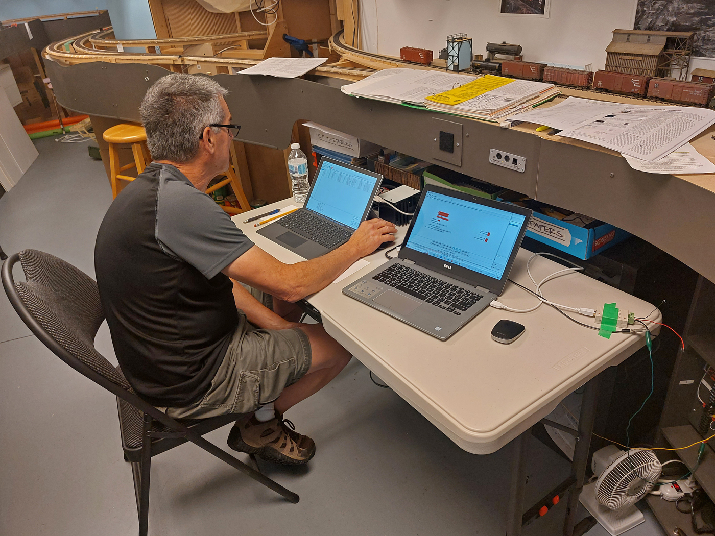
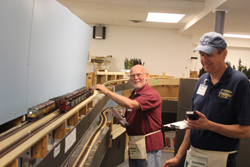
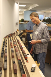
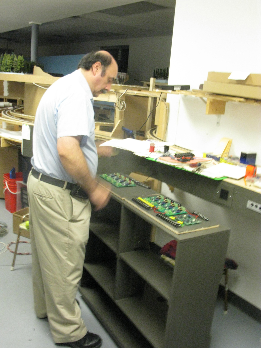
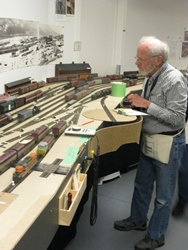
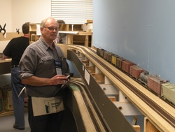
May to July 2023 | CPR Boundary Subloco qa & decoder pro work
One of my biggest weaknesses is electronics! Over the years, I have been very fortunate to have several good friends who can skillfully do decoder installation and programming work on my ever-increasing fleet of locomotives.
In April this year, during an Op session (of course) my LENZ command station failed, and the layout shut down. Much longer story here, however, we had a back up Command station and installed it and reset a bunch of stuff, all of which was WAY over my head.
This taught me that I need a better understanding of decoders and programming, so I bit the bullet and installed Decoder Pro on my laptop. With the help of several good friends, who had great patience, we plugged away at redoing all the locos. In the process, we speed matched sets, and set the locos up so their prototype speeds closely matched what the CVP T5000 throttles showed on their LED screens.
We have operated the layout several times since this work was done and it has revealed that there are still some “problem” locos, so we are continuing efforts to get them working better. I also have some very old decoders which are well overdue for replacements, so that will be done as well.
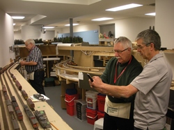
Here are a few photos of the fleet being worked on with Ken and Anthony investing a lot of time with me on this project. I am extremely grateful for their help and never-ending patience!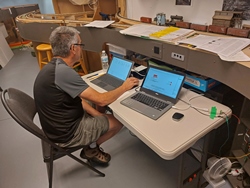

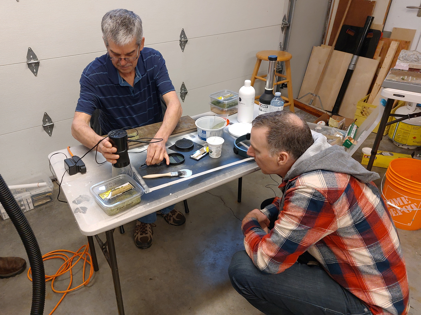
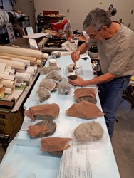
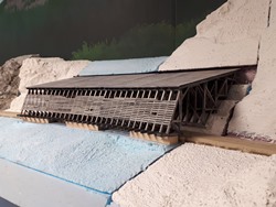
March & April 2023 | CPR Boundary SubKootenay River scenic base rebuild
Over the years, I have watched many model railroaders install very realistic static grass on their layouts. So, I decided it was time for me to attempt this skill. While there are lots of YouTube videos on this topic (some good, others not so good), I personally prefer hands on interactive learning.
So, I reached out to a friend who does great static grass work and recruited him to teach me. A couple members of my crew learned of this upcoming tutorial and asked to join us. We had three able bodied students, all with different applicators, and our teacher Marc.
We basically just set up some tables in my garage and brought all our collective materials together. I made several Styrofoam bases to experiment with. I also have a 12” x 48” diorama that I built for a clinic years ago, so decided I might as well try this out on some thing that would be used in the future. After practicing a lot and creating numerous mixes using different colors and lengths of static grass, I was confident enough to apply some to the layout. I used Woodland Scenics, which I find too uniform in color, with War World Scenics static grass which, in my opinion, is way better for what I am trying to create. Downside is they are based in the UK and I have not found a North American distributor yet. So, shipping charges to Canada are outrageous!
I chose some random locations along the upper deck where the scenery was “complete” and proceeded to try it out. While not always successful initially, I was pleased with the efforts as I continued to work. I actually went back over some of the first areas and added some more to enhance the look. Static Grass really adds a very fine and subtle scenic element and stands out in photos. Kudos to the person that invented static grass.
Here are a few photos that give an idea of how it is coming for me.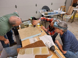

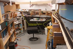
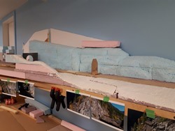
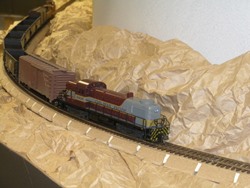
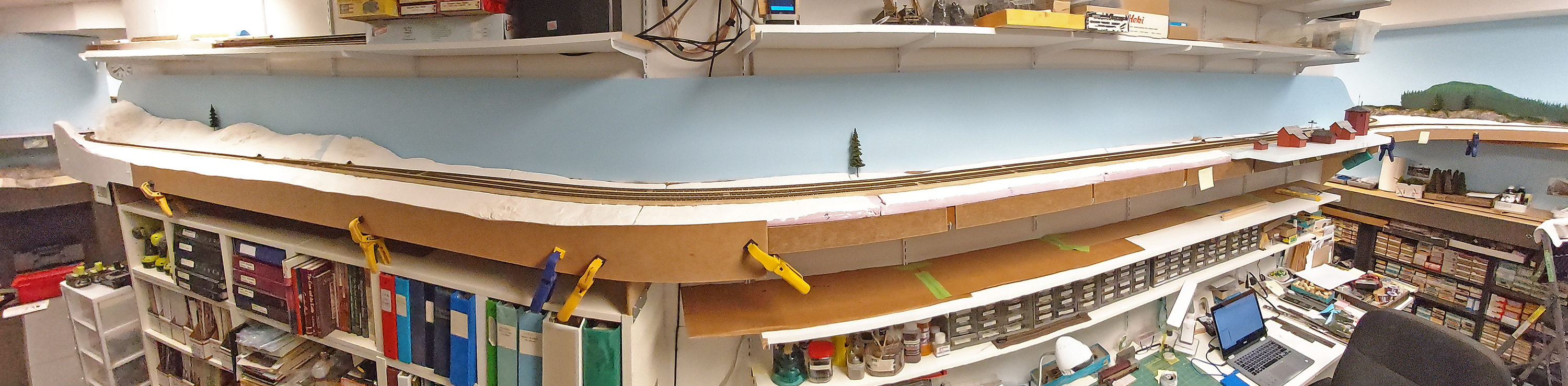
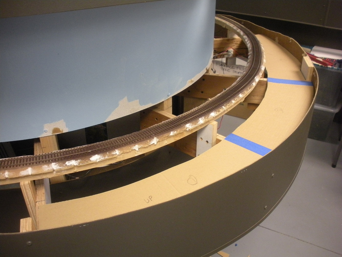
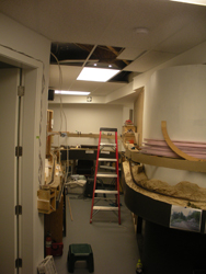
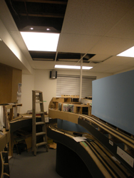
November & December 2022 | CPR Boundary SubKootenay River scenic base rebuild
In the Fall 2018 post we reported on how we removed “temporary” crumpled paper scenery and replaced it with the more traditional cardboard strips and plaster cloth. Well, that ended up also being “temporary” as well!
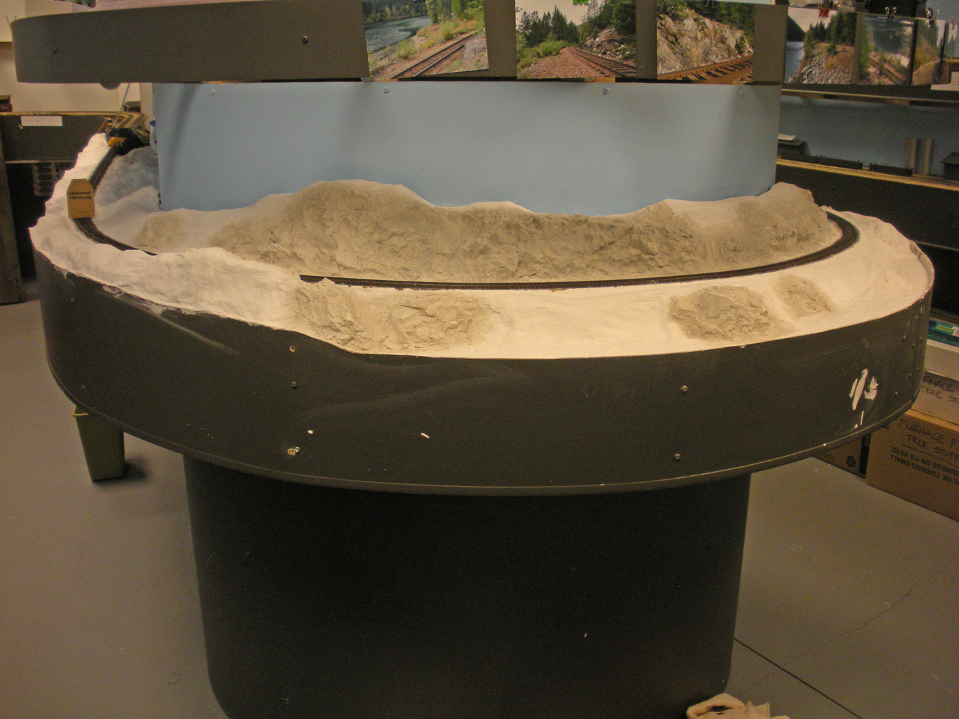
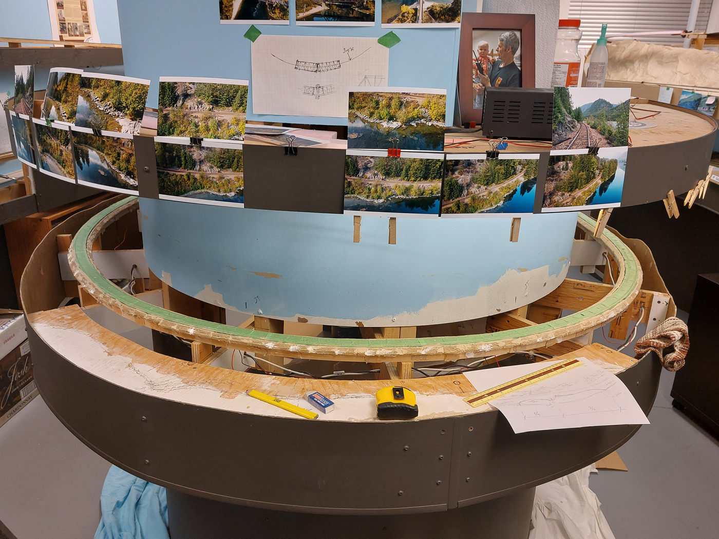
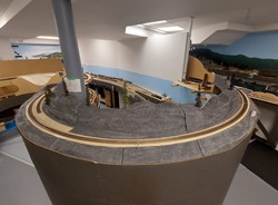
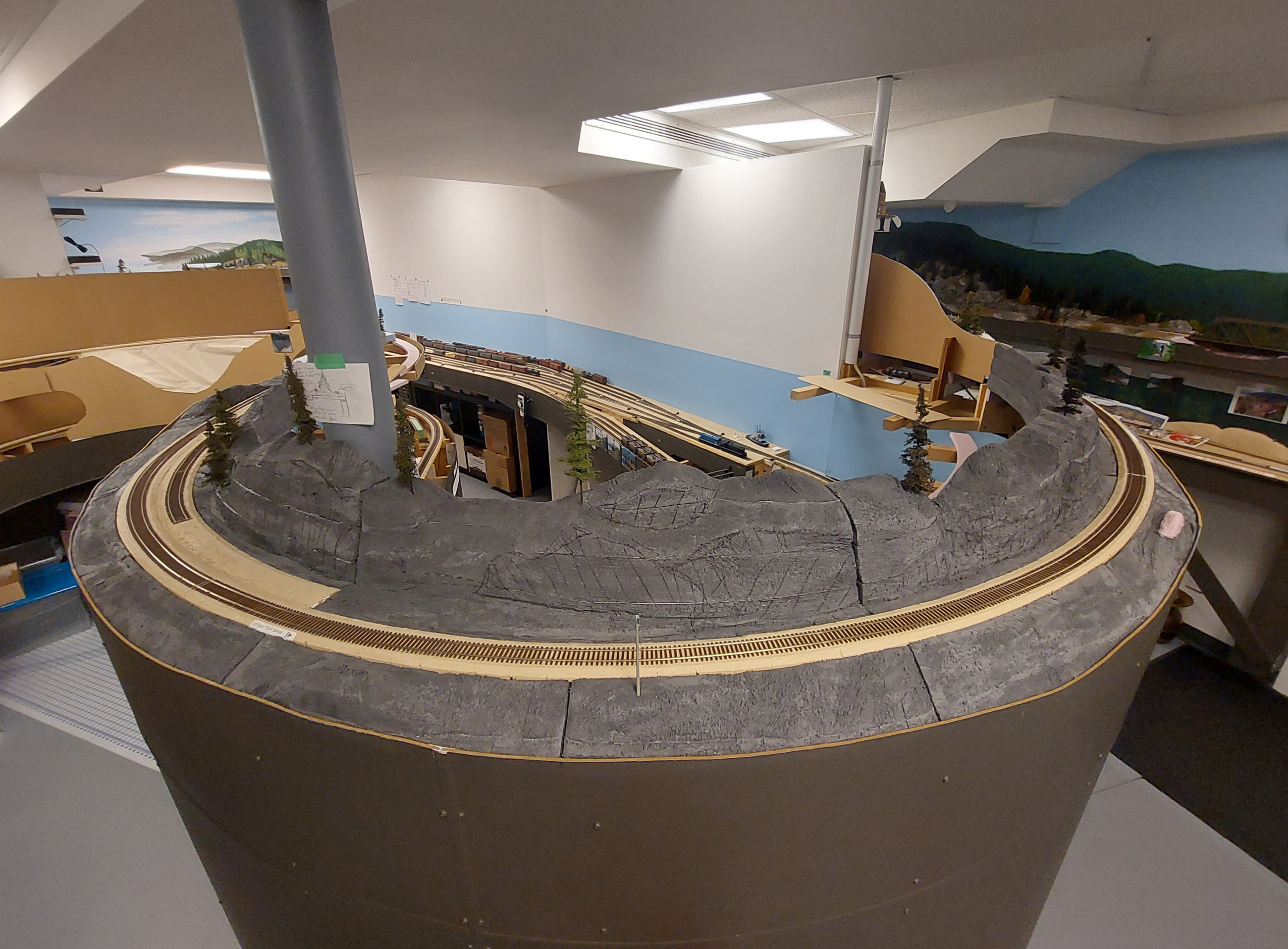
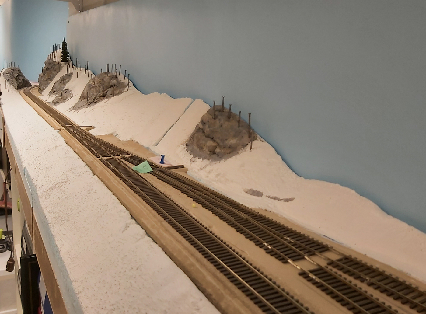
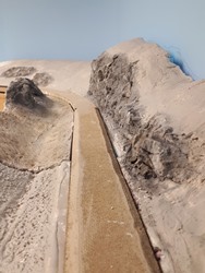
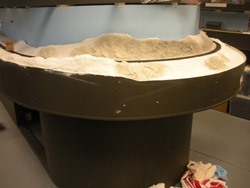
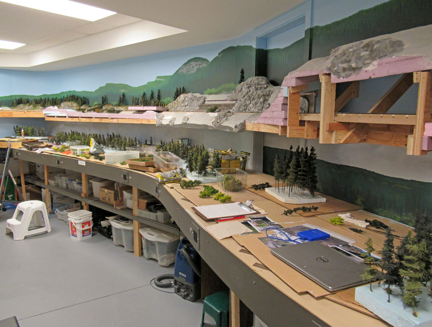
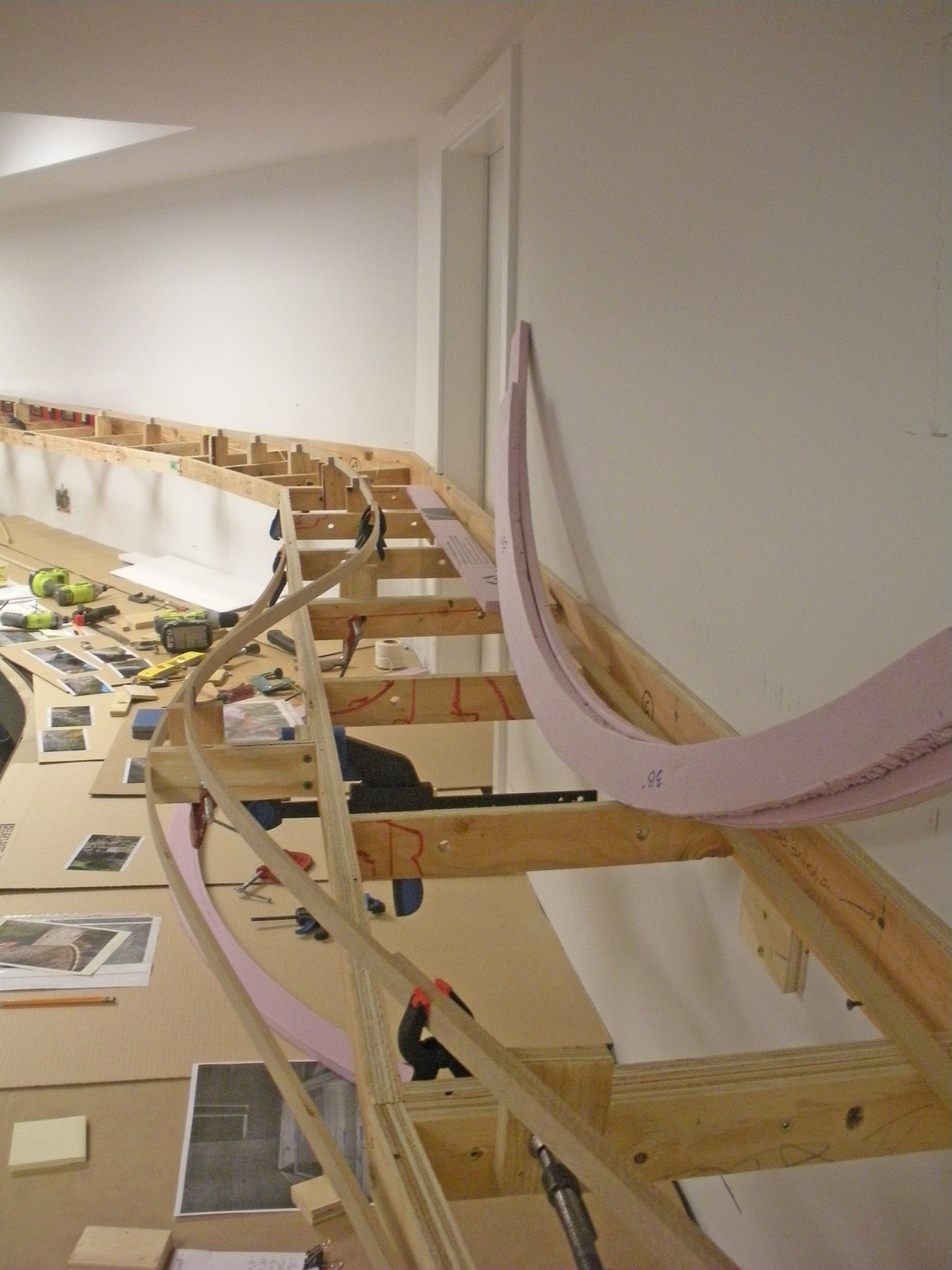
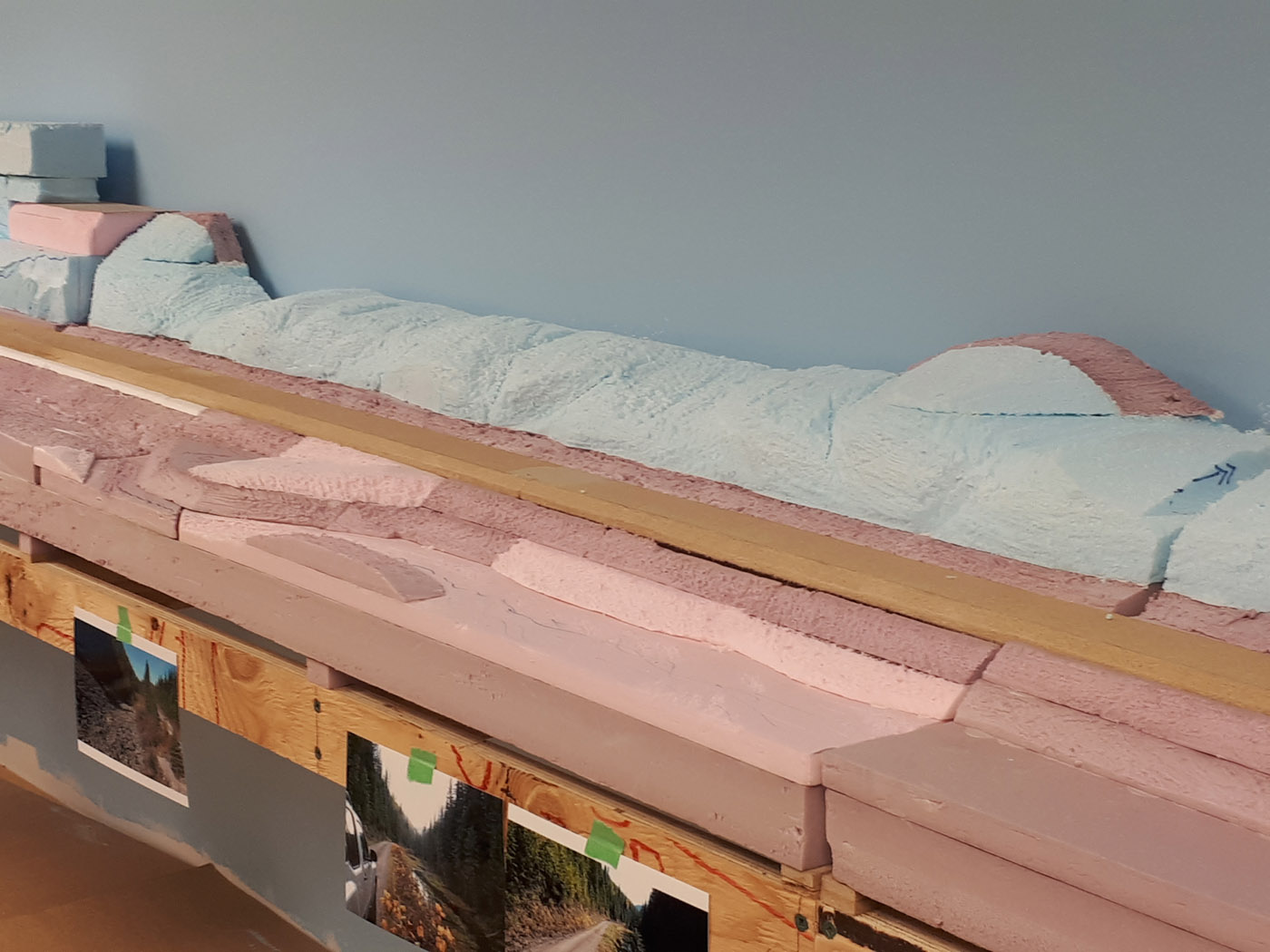
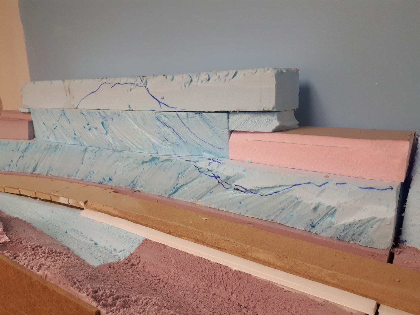
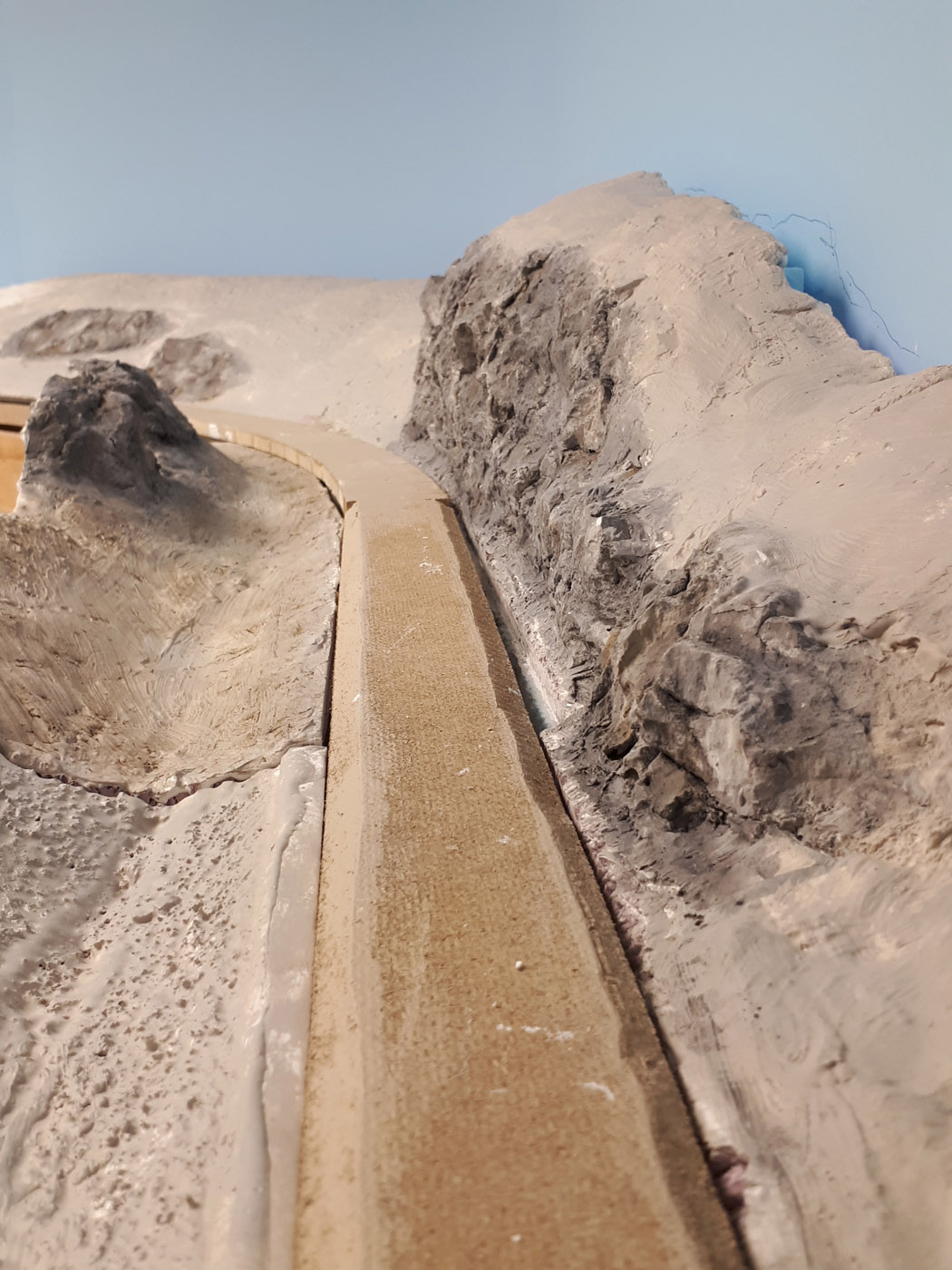
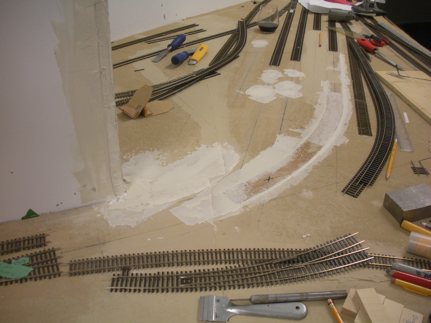
After completing extensive drone photography of this area, it became apparent that the current plaster landforms di not accurately capture the topography of this area. So, the plaster work was completely removed. Then, grey Styrofoam landforms were created and shaped to reflect the character of the actual site. The landforms were extended eastward towards the new South Slocan siding as well.
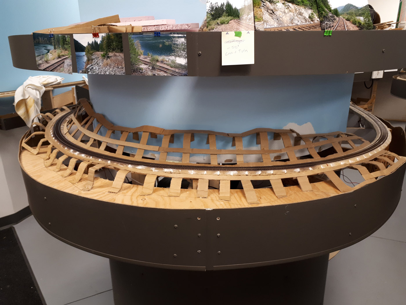
Here are a series of photos that show the removal of the previous plaster landforms and the creation of the replacement grey Styrofoam landforms;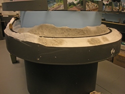
This is the previous landform made with cardboard strips and plaster cloth.

Shows the scene with all the with cardboard strips and plaster cloth removed. The drone photos clipped to the fascia above the scene were taken at the prototype site.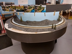
Shows the current state of the foam landforms ready to be sceniced with my typical techniques.
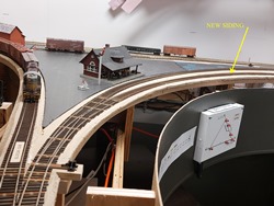
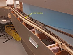
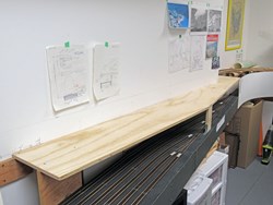
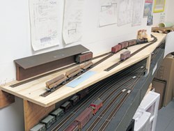
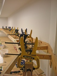
Fall 2022 / Winter 2023 | CPR Boundary SubSouth Slocan Siding Addition
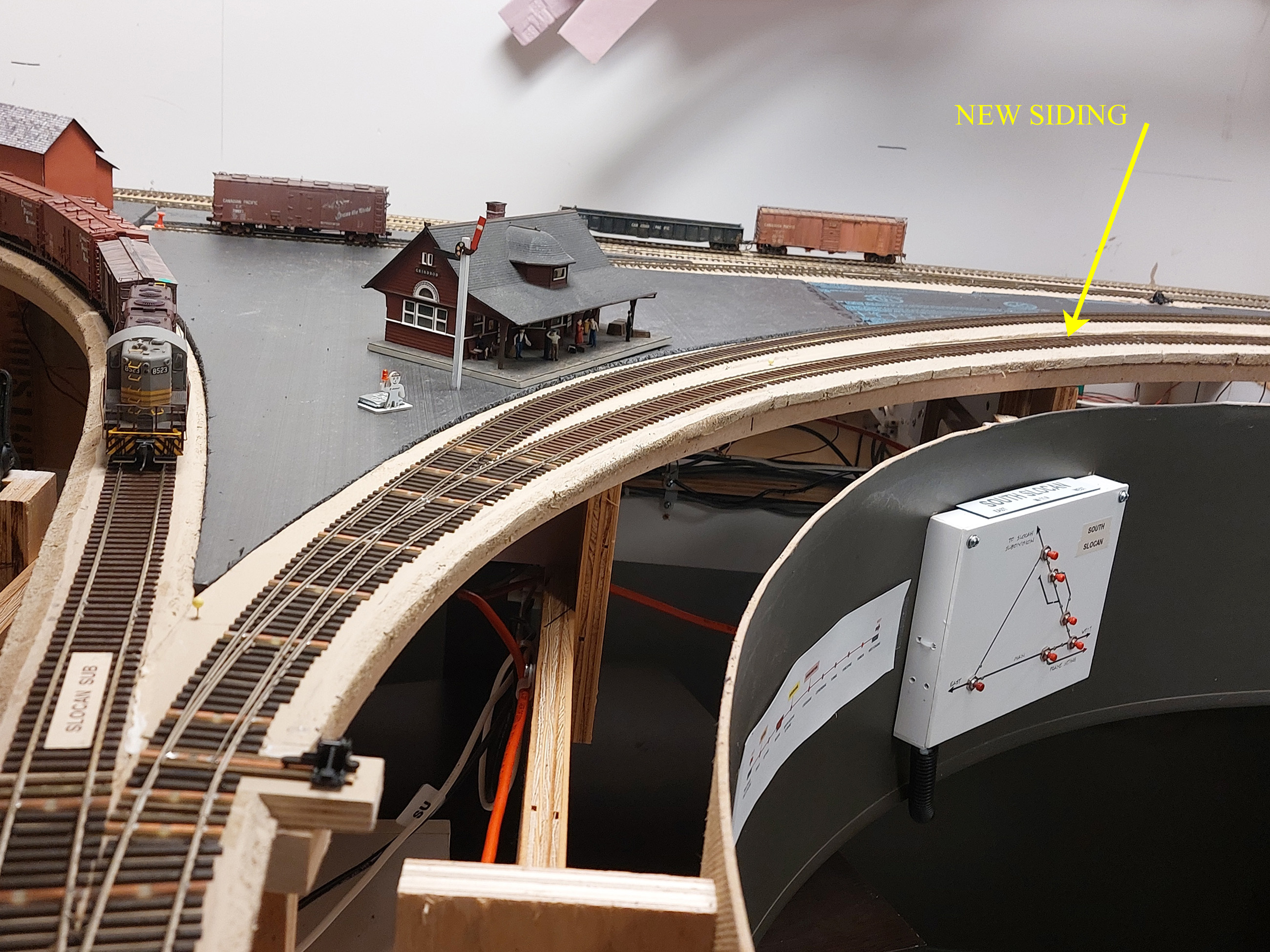
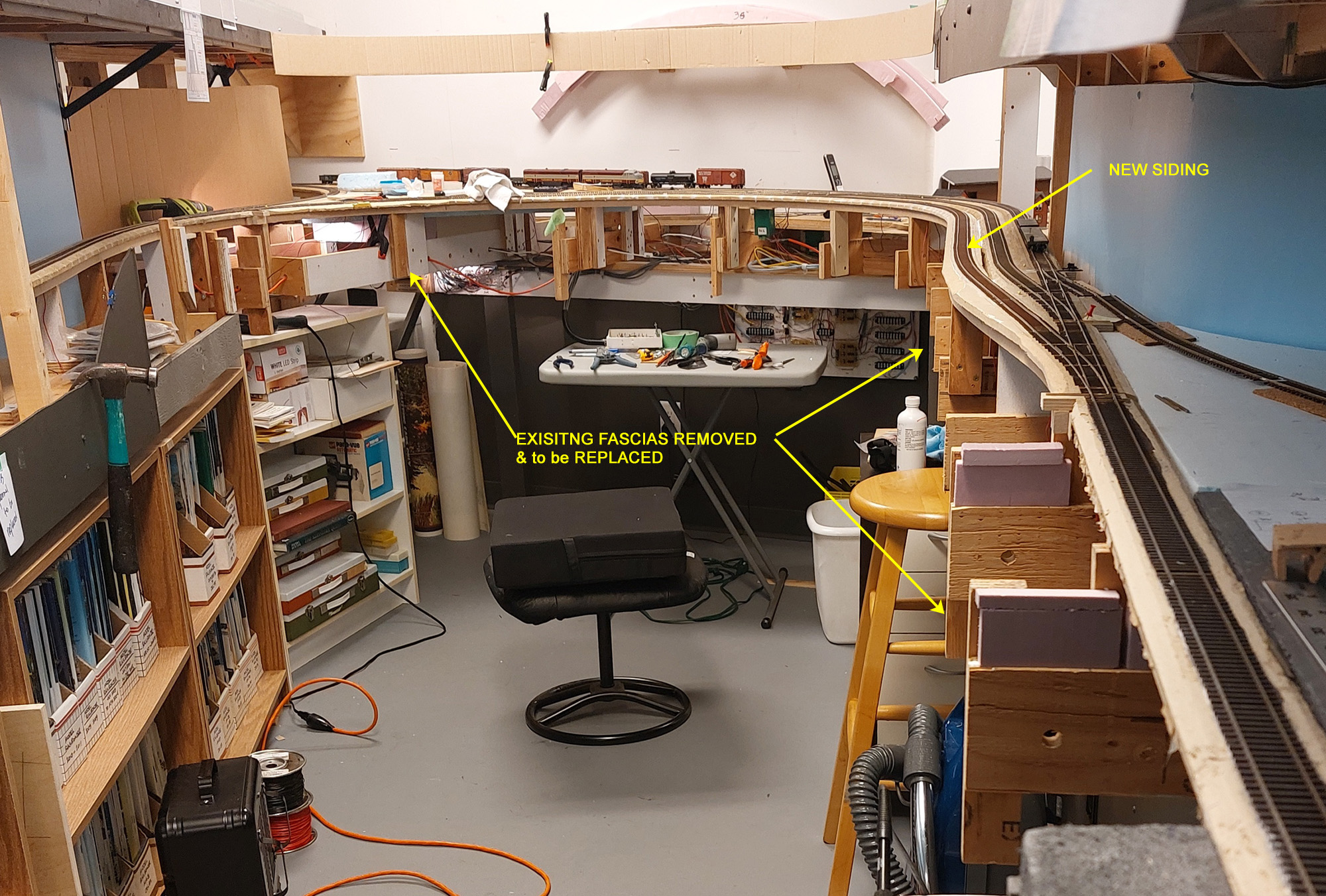
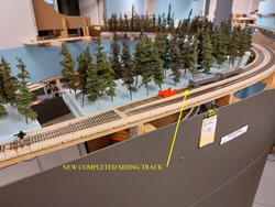
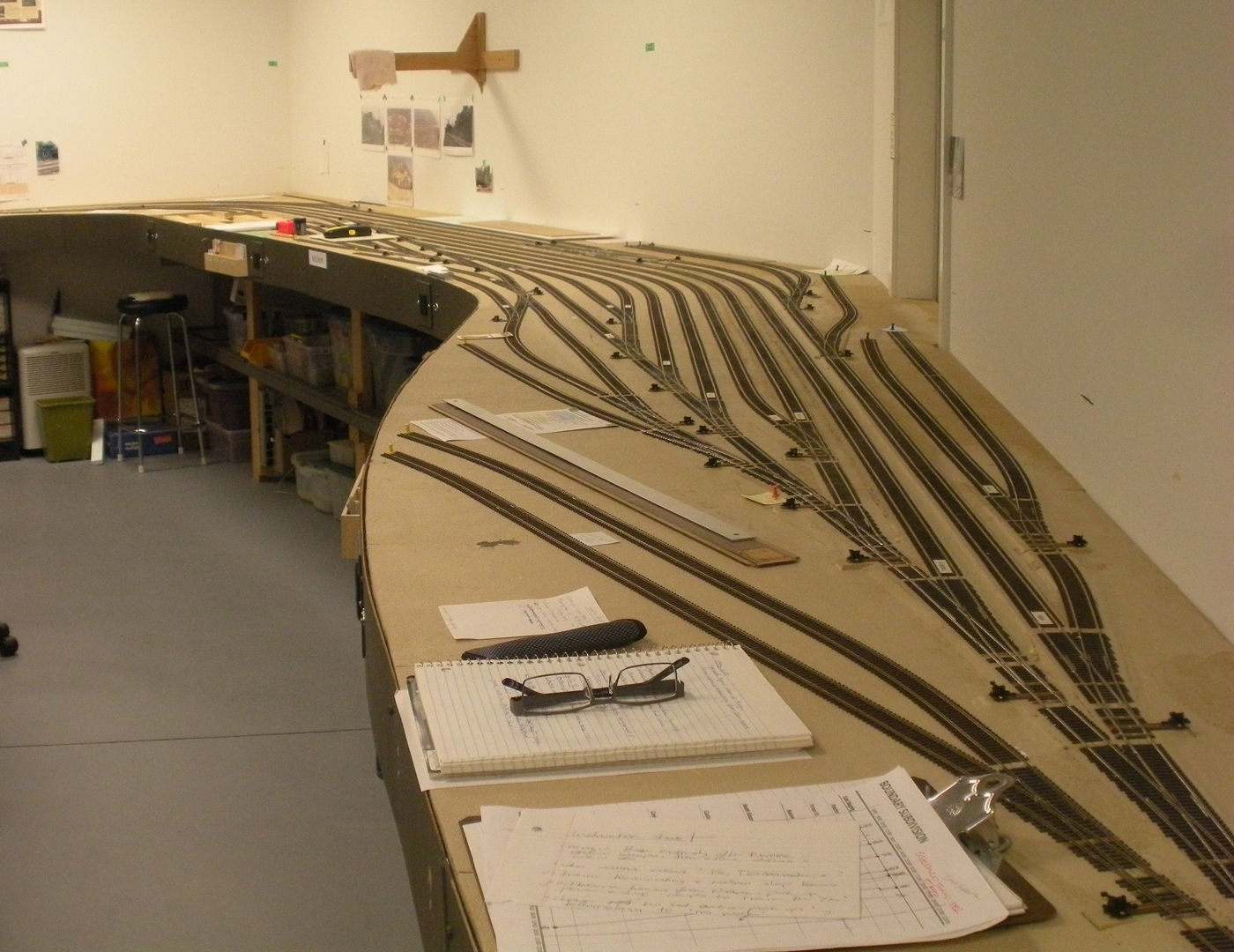
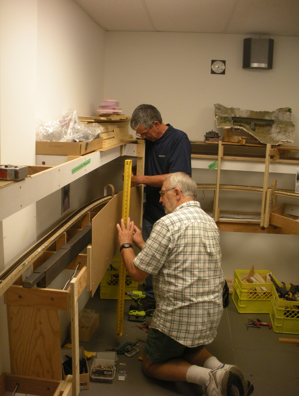
One of the key feedback learnings from my RMMBC 2022 Op sessions was that South Slocan REALLY needed a proper siding. There is a lot of traffic between Nelson and Castlegar on the layout, and this was the only location where meets could be scheduled. So, I promised the home team that I would make this a priority, little did I anticipate how much work it would be!
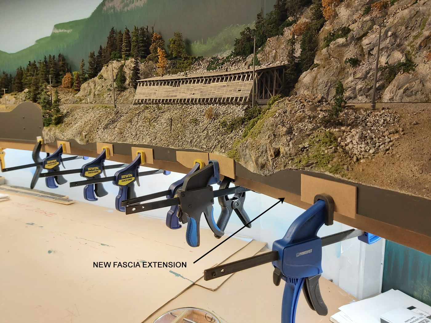
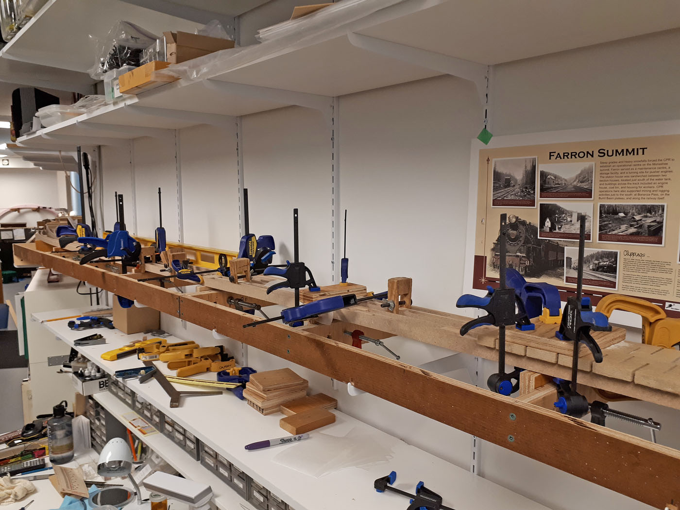
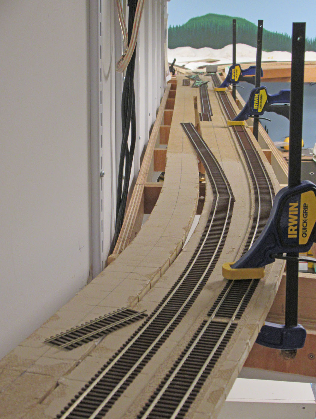
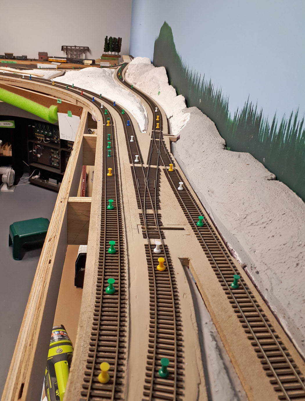
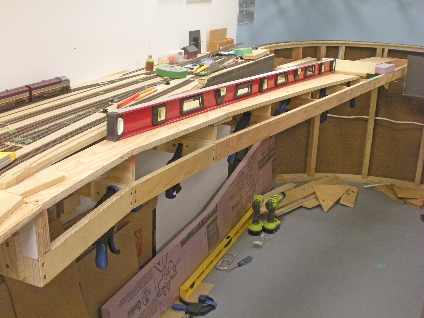
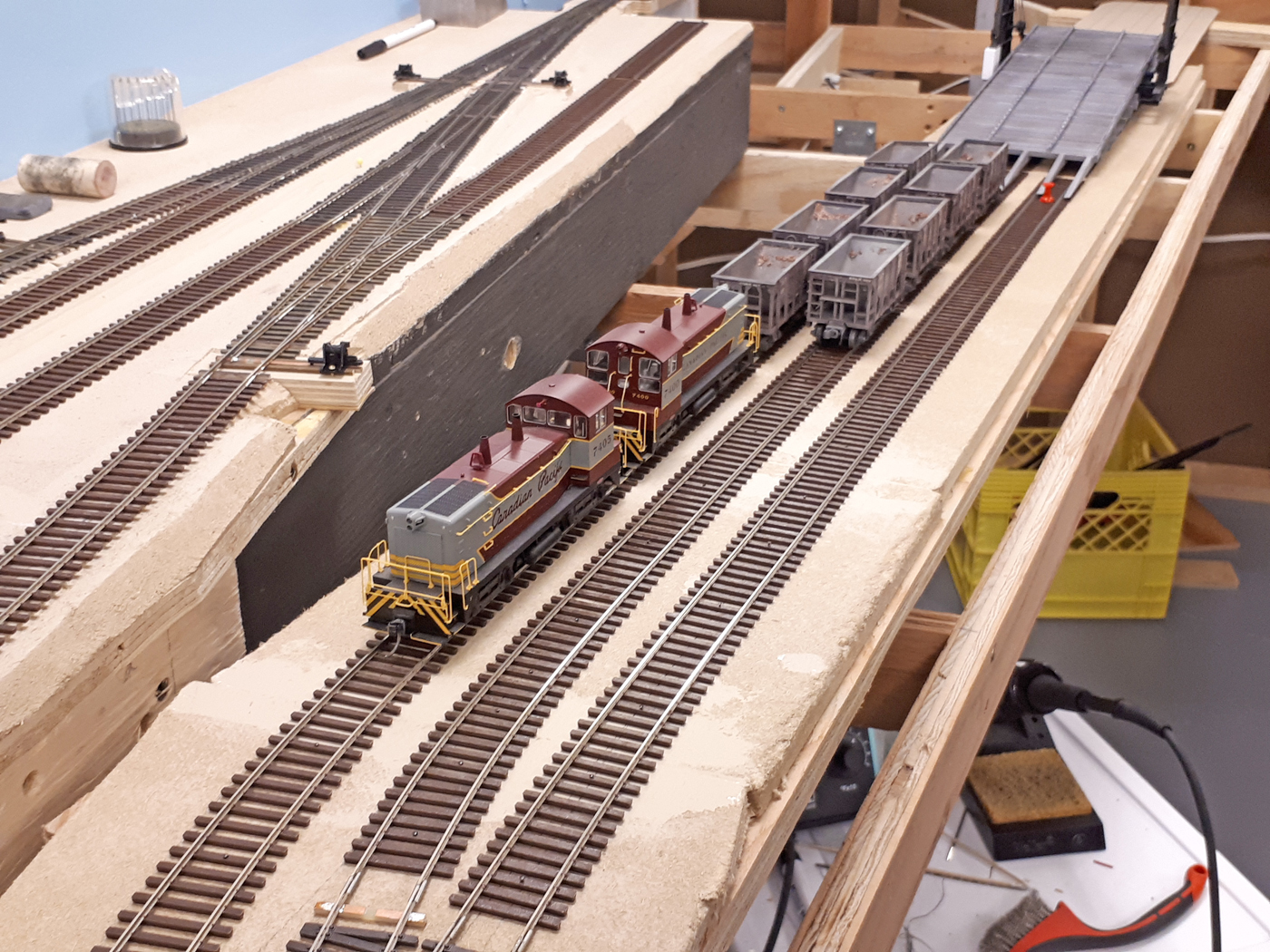
This project involved removing & modifying about 15 feet of completed fascia, extending the cantilevered framing along this same 15 foot length. Adding many new track feeders, modifying several commercial turnouts, cutting into the existing mainline track at two locations, and installing the new 23 foot long spline roadbed system and track.
As of this writing, I still need to modify/rebuild some turnout control panels and install several new powered switch machines. As well, this area will get our grey Styrofoam landforms too.
October 2022 / February 2023 | CPR Boundary SubDrone REsearch Trip
In early October, I headed off on my third drone research trip covering the areas that I model. This was the second time I used my own drone. From experience with previous trips, I decided to purchase several more batteries since they get depleted fairly quickly, especially in windy conditions – which the BC mountains tend to be!
Prior to the trip, I marked up a map of the Boundary Sub area with potential locations and what I wanted to capture. I then developed a travel plan that spanned five days and covered a couple thousand kilometers. On this trip I was able to remain on public roads and did not need to drive onto the abandoned grades as I have done in the past.
As noted in my previous posts concerning the use of drones, I am very careful where I fly, and I obtain permission where appropriate to do so.
Unique to this trip was a confrontation with a bird! I wasn’t aware of the nest in a tree across the river from where I launched, however, as I approached the opposite bank an ear splitting screech came from the trees and a large bird flew directly at the drone! I had read about others who had these experiences, sometimes ending with the destruction of the drone and harm to the wildlife. I immediately dropped the drone down closer to water level and retracted it rapidly to reduce the perceived risk to the birds. After that, I chose how I approached the bridge I was filming with respect for where I determined the nest was located. Glad I didn’t have to wade into the river to fetch a soggy drone!
Here is a map of the Boundary Sub with the locations where I did photography noted on it.
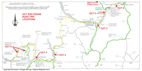
Below is a sample of some of the still photos taken. The videos are too large to include here.


-
You can view more of my drone photos in the Prototype Photos section of the web site.


-
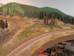
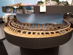
January 2022 / February 2023 | CPR Boundary Sub
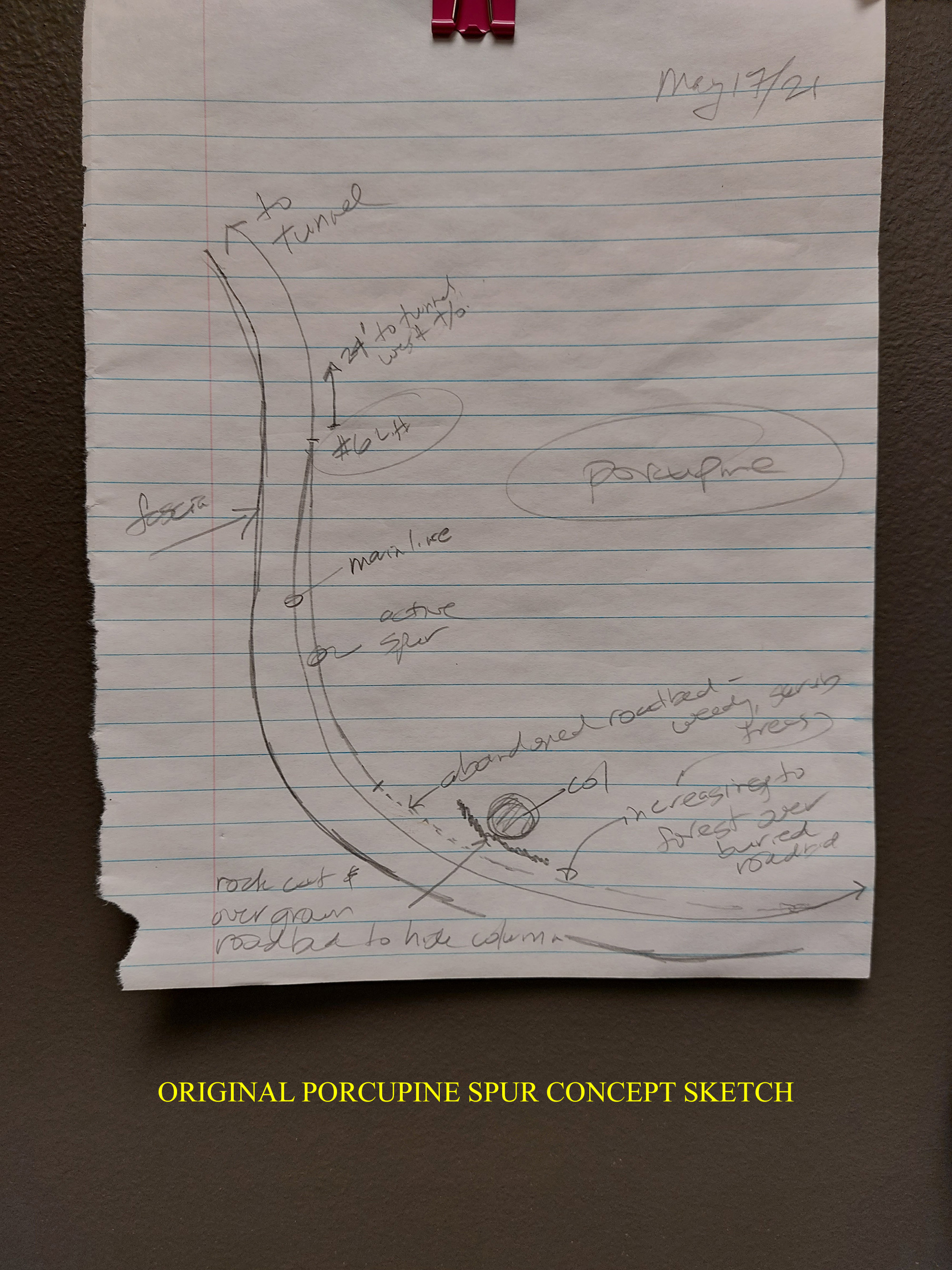
Porcupine Siding Relocation & Grey Styrofoam Landforms
The original concept for the Porcupine location (just east of Farron) was to construct a poorly maintained spur that was the remnant of the original siding. The spline and roadbed were installed for it many years ago and then this project drifted lower on the “to-do” list.
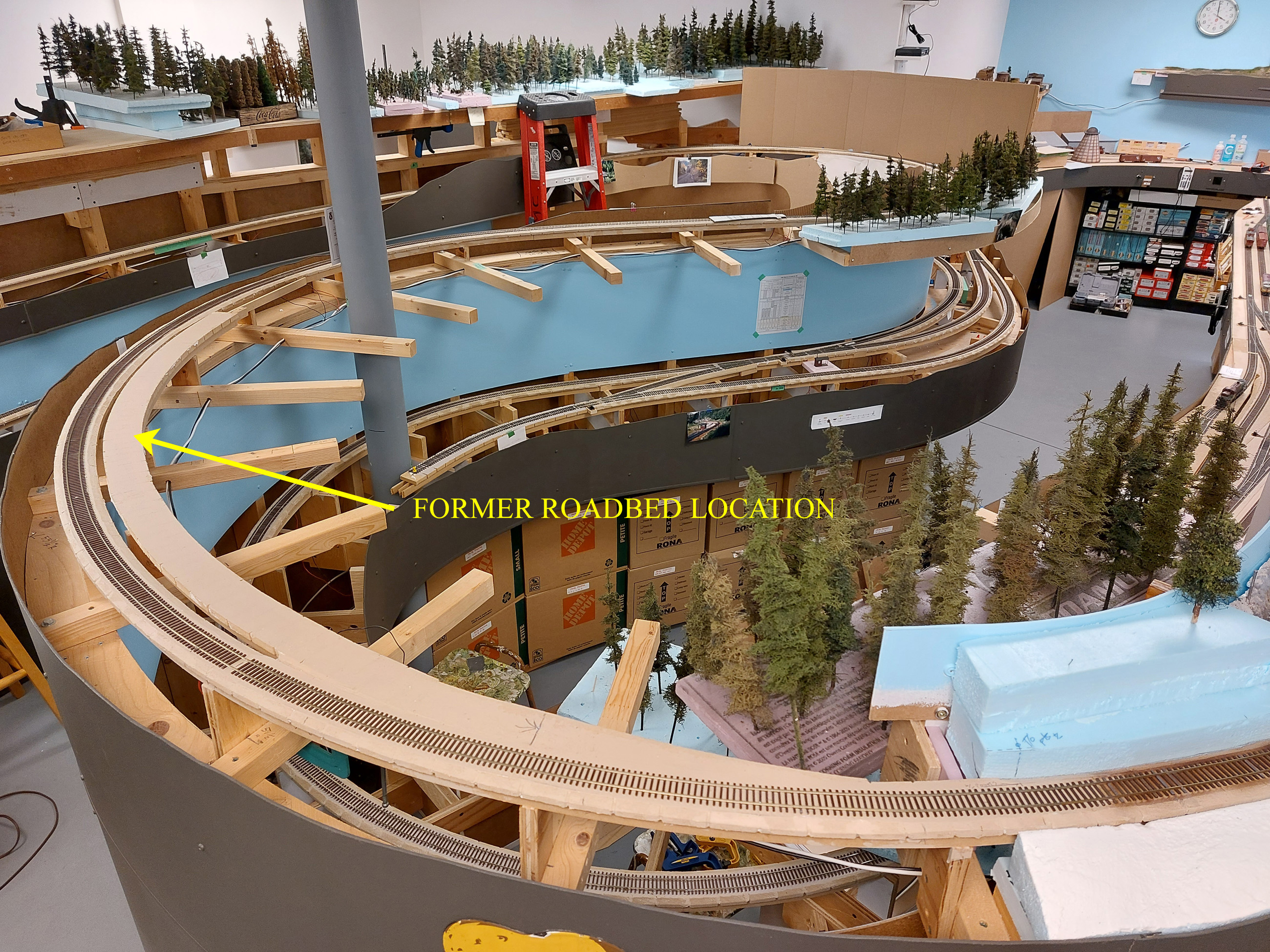
Early in 2022 it occurred to me that this spur would be too close to the east end of the Farron siding, so I decided to rip out the original roadbed and construct a new one further east and with the turnout at the east end instead. This work would be completed in conjunction with the installation of new Styrofoam scenery landforms eastward from the end of Farron towards the site of the Porcupine fill.
-
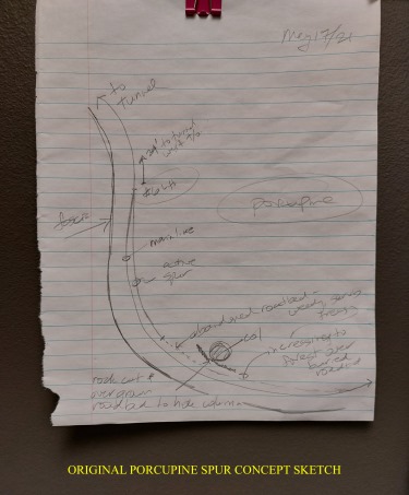 Back in May 2021 I developed this rough sketch of what I thought the Porcupine spur location might look like.
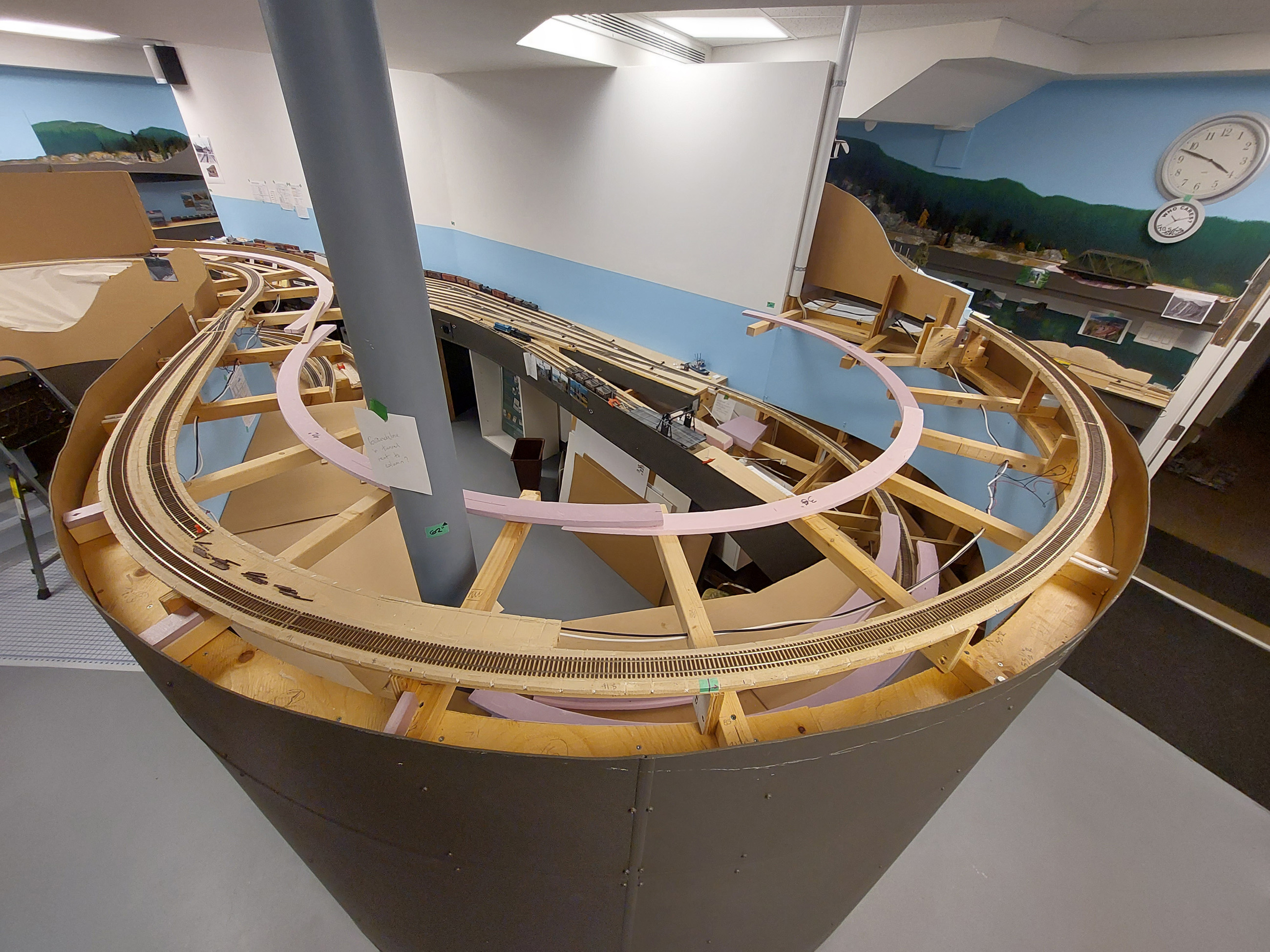
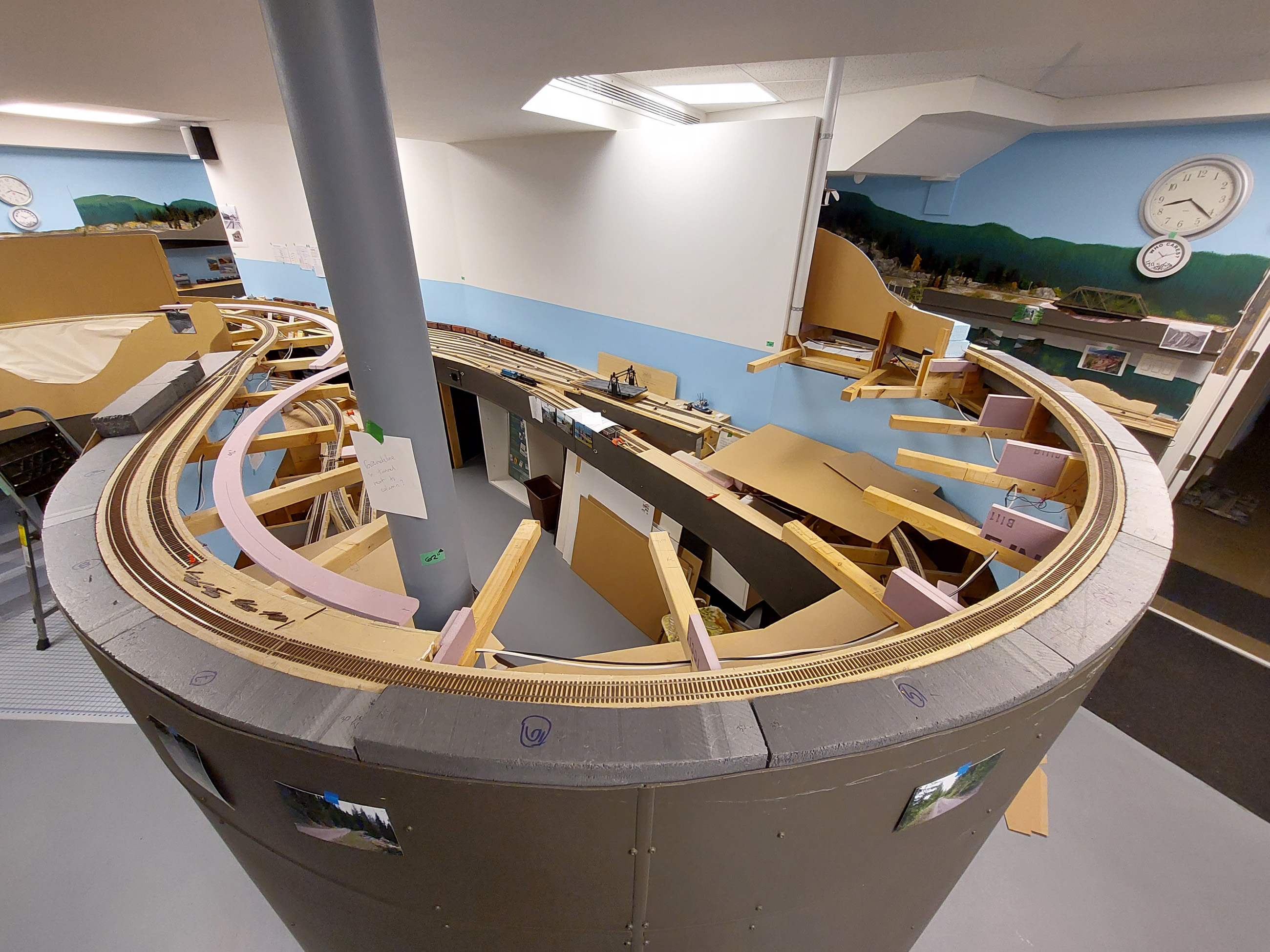
The actual work commenced in February 2022 with the removal of the old roadbed and the construction of the new roadbed for the Porcupine spur. We used the established method for the spline and roadbed. The mainline was cut to accommodate the modified Shinohara turnout that would connect to the new spur track. We used Micro Engineering code 70 flex track for the spur. It was modified to spread the ties out and look rattier.
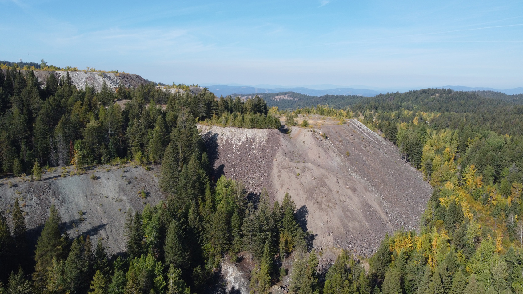
At this point, the project took a hiatus until June, when the work and construction of the Styrofoam scenic landforms along this large curve resumed. This track is a dominant scene as you enter the train room and is at about 64” above the floor. After reviewing our large photo & drone video archive of that part of the abandoned line numerous photos were selected to guide the development of these scenes. These photos will also guide our selection of colors and textures, like has been done in other areas of the layout.
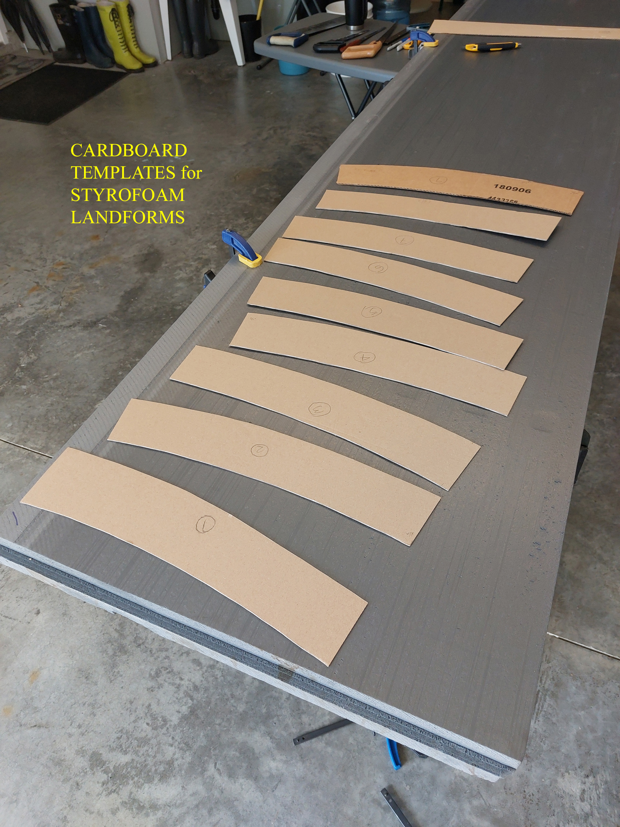
At this same time, I was given several sheets of a different type and color of Styrofoam. It is higher density than what I had been using, but, more importantly – it is Grey! Dupont is the manufacturer. The neat thing is that even in the contoured state, before any scenic materials are applied, it looks way better than the typical blue or pink Styrofoam!
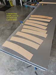
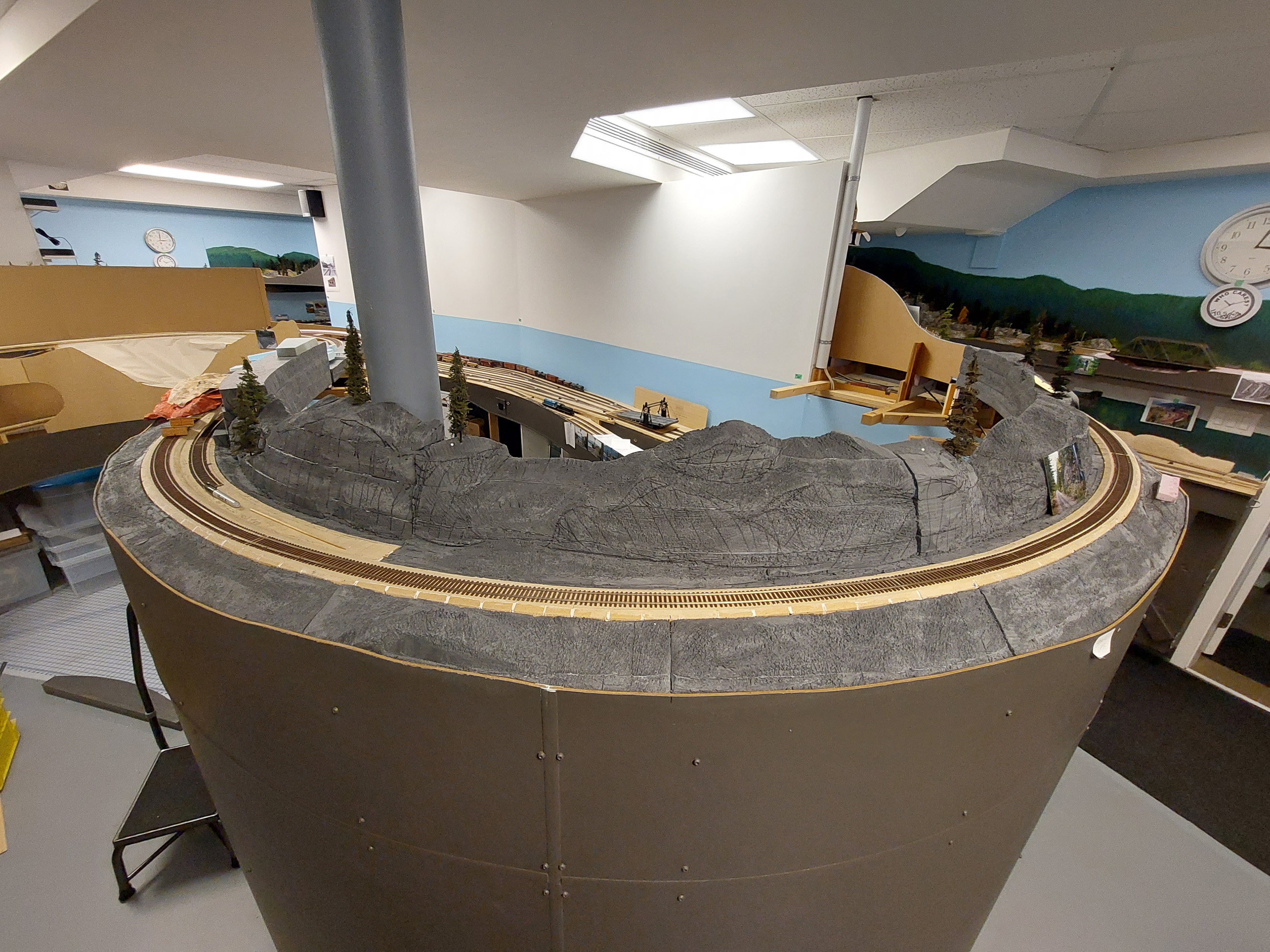
Cardboard templates were created for the required individual pieces and laid out on the foam sheets to use it as efficiently as possible. A variety of tools were used to cut and shape the foam into the desired shapes using techniques utilized in previous areas of the layout. The landforms were also marked with proposed rock casting locations with a black marker.
At the time of this post, there has been no detailed scenery work done on any of these landforms, however, they remain visually effective for the time being.


4th Division, PNR YouTube Videos
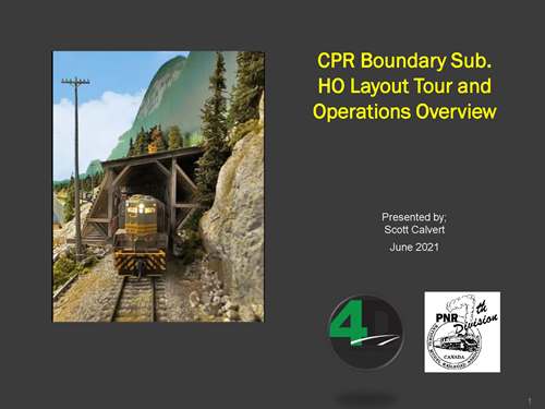
Early in 2021, I was approached by the team of 4th Division PNR/NMRA members that were producing their excellent Zoom presentations during Covid. After a little arm twisting, I agreed to do a Layout Tour presentation, and subsequently, also agreed to do a brief Layout Ops Overview presentation as well.
They were recorded and have been posted both on my YouTube site and the 4th Division PNR site. Here are the links if you are interested:
CPR Boundary Sub Layout Tour 2021;
- Scott Calvert YouTube Link; https://www.youtube.com/watch?v=P4cYQ4B0Zgg
- 4th Div YouTube link; https://www.youtube.com/watch?v=nan_8OIVhdg
CPR Boundary Sub Layout Operations Overview 2021
- Scott Calvert YouTube link; https://youtu.be/VhU8bXQmokc
- 4th Div YouTube Link; https://www.youtube.com/watch?v=eHrMAg42fyQ
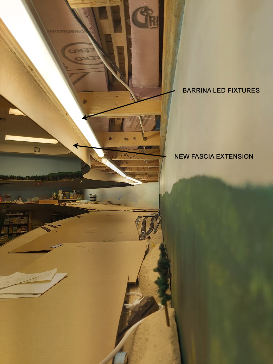
April 2021 | CPR Boundary SubNelson Yard LED Lighting
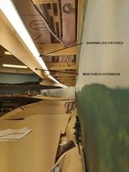
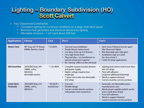
After conducting research into LED lighting, I opted to install commercial 48” long LED T5 fixtures manufactured by Barrina along the entire 40 foot length of Nelson yard. They are 4000k fixtures which works well with the other lighting in the room. I purchased these through Amazon Canada, and when you consider all costs for LED lighting installations, they were cost and time competitive.
I wanted something that was going to stand the test of time because I didn’t want to face the prospect of removing and replacing lighting over my main yard! This system is a “plug & play” system, it literally took me a morning to install all 8 fixtures, hook them up and test them – and I was done! Here is a copy of the Installation Guide for these fixtures;
Unfortunately, my upper deck fascia did not visually obscure the LED tubes satisfactorily, so a small section was added along the bottom edge of the existing fascia.
-
Click the image below to see more on the lighting project.
-
-
Fall 2020 / Summer 2021 | CPR Boundary SubFarron Landform SCenery
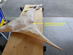
Our previous Spring 2020 Post featured the beginning of the scenicing process for the Farron siding and wye area. At that time, all the basic landforms were created, sculpted, and had received the primary coats of plaster and rock castings. Essentially, it looked like a winter scene!
In September 2020, we resumed work in this area. First up was to create and scenic the landform that rests within the wye area and the adjacent landforms. These were needed first because this area was used for the photography of the CPR water tank used in a November 2021 Railroad Model Craftsman article authored by Patrick Lawson in the.
Then, the landforms previously created in the spring were scenicked using the same techniques utilized for the previous scenery landforms on the layout.

And, for fun, my son flew one of our drones INSIDE the train room and took these photos. Safety is paramount when flying drones indoors, and he is a fully registered and licensed drone pilot.
Pending future work to complete this area include; backdrop painting completion, installation of trees & foliage, adding various misc. detail items, and static grass applications.
Fall 2020 / Early 2021 | CPR Boundary SubFarron switch Machines & Control Panels
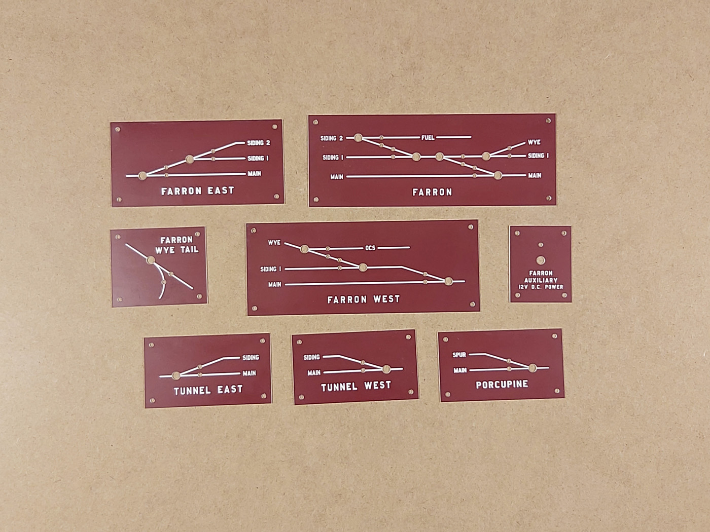
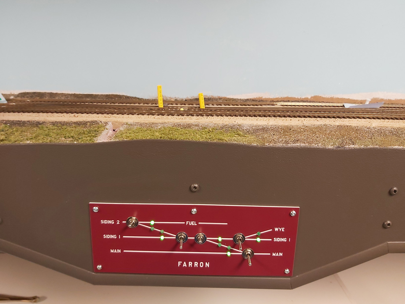
Farron is the highest of the two summits on the prototype Boundary Sub. and mine sits at 67” above the floor. I am 6’-2” in height which makes it at my eye level, but too high for most model railroaders to view comfortably. So, it was decided to power the switches at this location with Tortoise machines and fabricate custom made fascia mounted control panels.
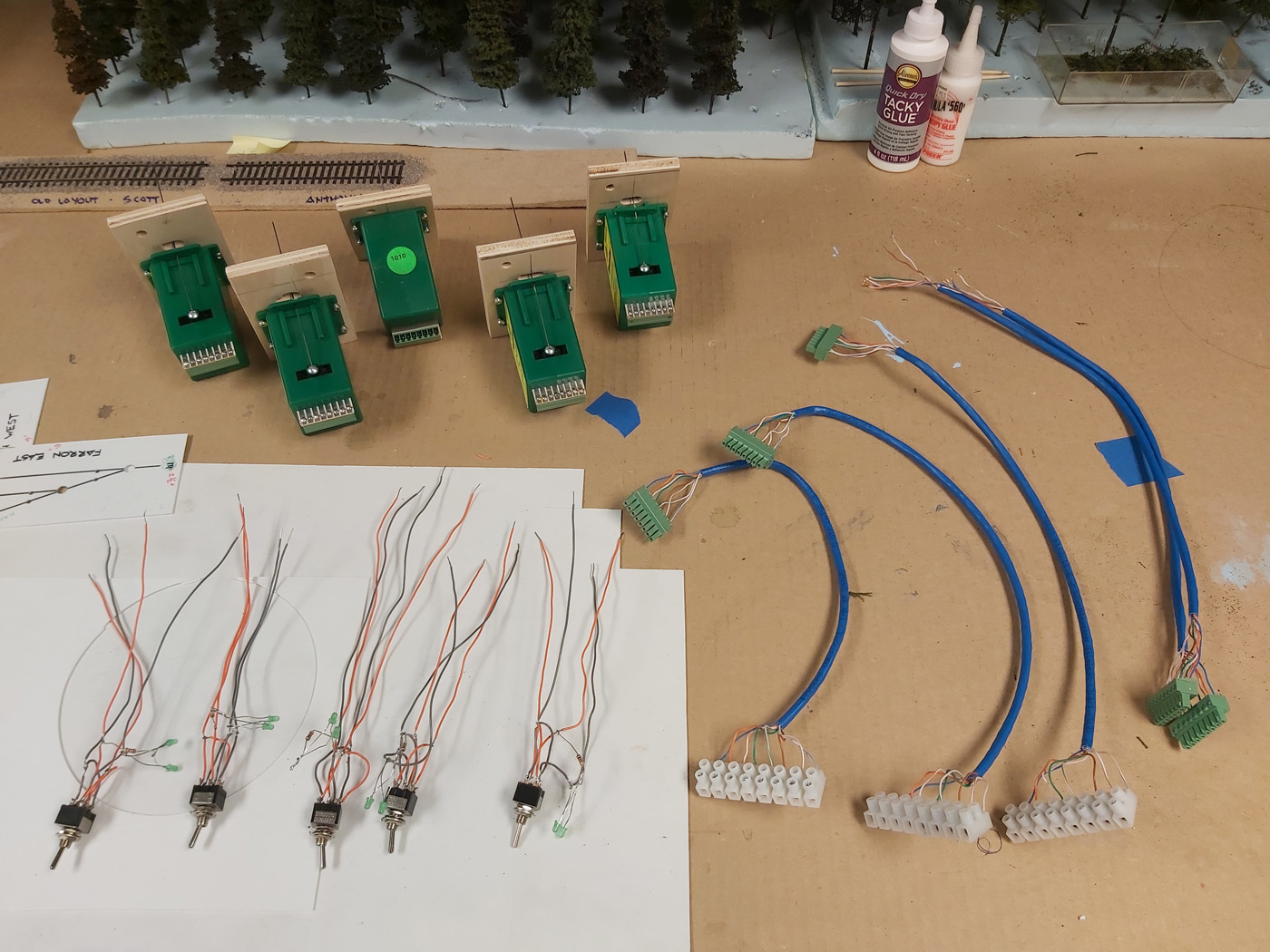
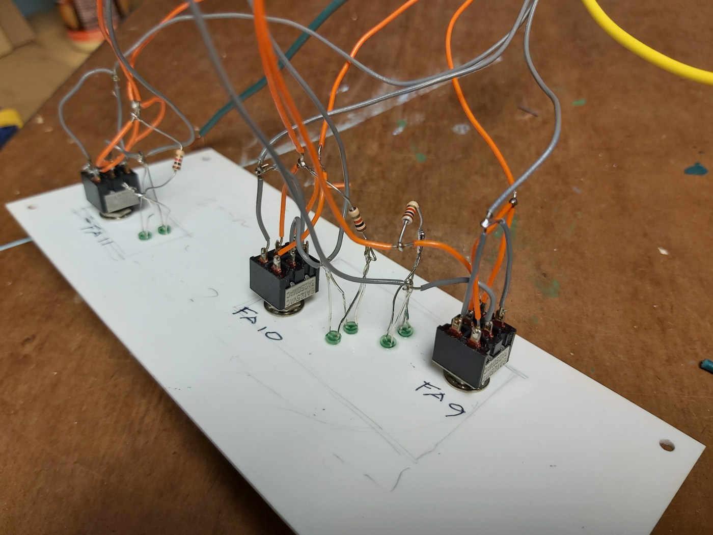
This work spanned many months and involved several cardboard and styrene panel mock ups, and some test wiring. I mass produced most of the assemblies at the work bench to make the in-situ work as easy as possible. The ultimate work included the installation of 11 switch machines and 4 control panels and was completed in February 2021.
The panels are custom cut Lamacoid material made by our local Fast Signs franchise based on my design sketches. The burgundy color was chosen to complement the classic CPR paint colors and the lettering is the actual CPR font that I was able to obtain.


November 2020 | CPR Boundary SubFarron Structure & Platform Completion
In the spring of 2020, a mock up of the Farron scene and proposed structures was developed. It was then left dormant while work proceeded on other aspects of this part of the layout. See previous March 2020 Post.
In late 2020 we resumed work in this area as part of the advancement of the Farron landforms and scenery. Work involved creating a removable Styrofoam landform laid out specifically for the cluster of buildings using several prototype photos as a guide. This base was covered with the same basic scenery materials as the surrounding landforms. A hardboard fascia was glued onto the Styrofoam base and painted to match the layout fascias.
As of January 2023, the platform remains removable for photography convenience, safety reasons and for access to the turnouts beyond the buildings. It will receive a random application of static grass and final foliage and trees at the same time the rest of the entire Farron shelf area does.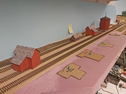


- October 2020 | CPR Boundary Sub
Drone Research Trip
In the summer of 2020, I purchased a DJI Mini-Mavic drone primarily to use for research along the Boundary Sub. This is a small drone with limited features which made it quite affordable. Although it did not need to be registered due to its light weight, I have taken online lessons on how and where to use it safely and effectively. I am EXTREMELY careful where and when I use it. I also had written permission to fly it on the C&W Trail which includes sections of the abandoned Boundary Sub roadbed.
Here is a map of the Boundary Sub with the locations where I did photography noted on it.
Below is a sample of some of the still photos taken. The videos are too large to include here.


You can view more of my drone photos in the Prototype Photos section of the web site.
- May 2020 | CPR Boundary Sub
Cabin Tree Flocking Trip
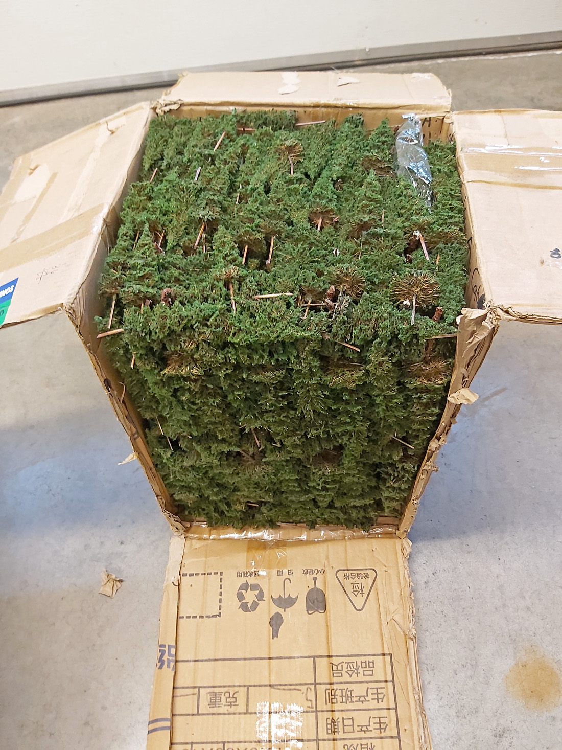
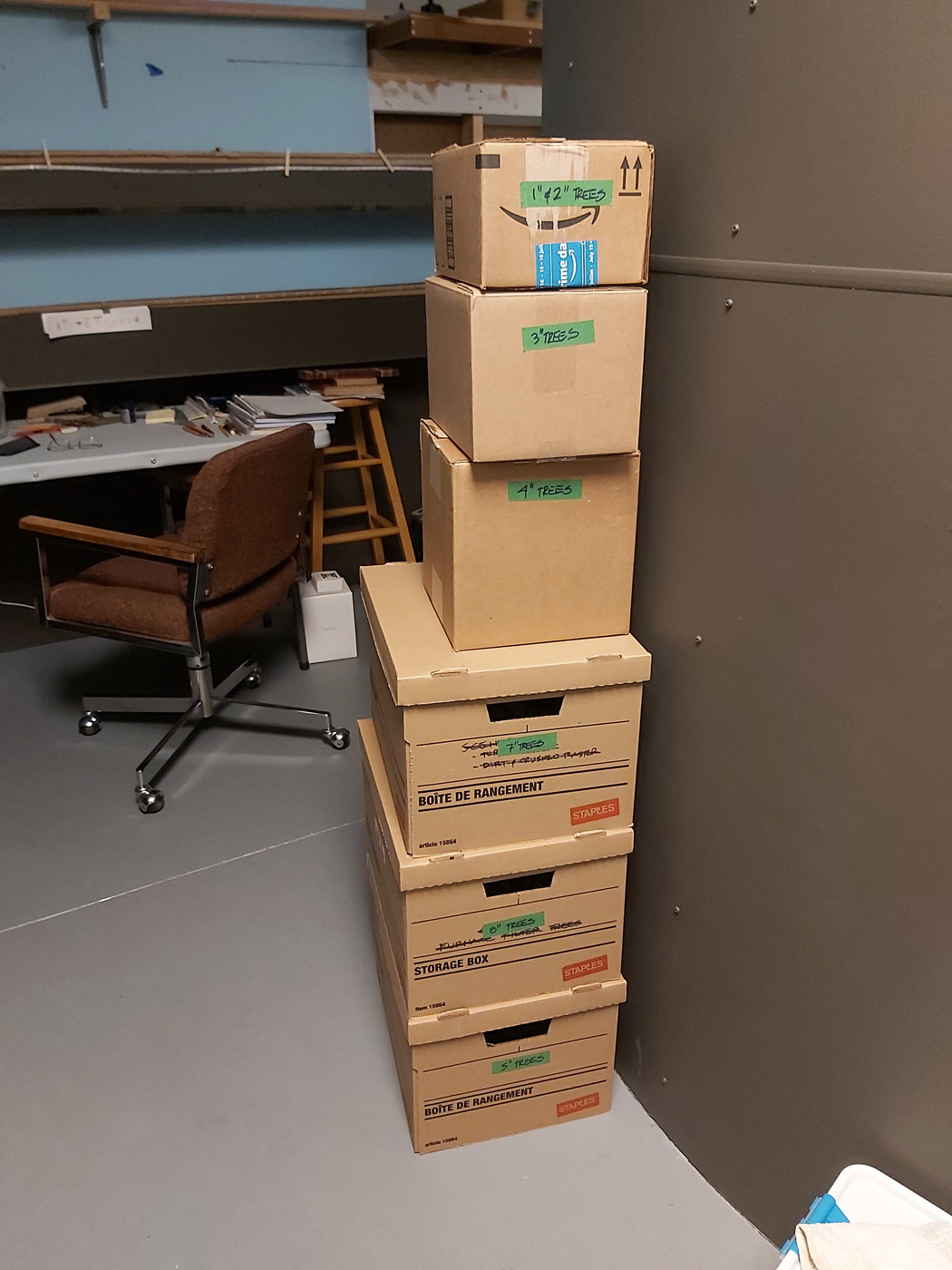
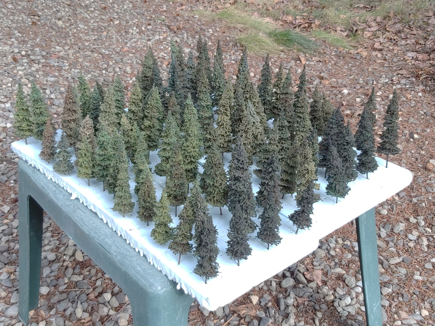
Many years ago, a local group of modellers sourced and purchased commercial conifer trees from a supplier in the Philippines. Given the growing demand for trees as the scenery on the layout continues to progress, I placed another order for about 850 trees varying from 1.5” to 8” in height. They come in a rather bright green color, so we flock them with the same six mixes of Woodland Scenics and Scenic Express materials that are used on the furnace filter trees giving them a visual family look.
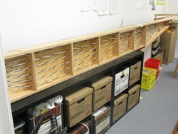
The trees arrived in a highly compressed state in one cardboard box. I had to slice the box sides apart to get the trees out, and then had to meticulously untangle them. After I sorted them into sizes, I restocked them in a series of boxes. Hard to imagine that “cube” of trees eventually occupied almost 6 individual boxes!
Below are a couple of photos of the boxes, and a couple of the completed trees in a Styrofoam base. Ready for planting!


- October 20220 | CPR Boundary Sub
Upper Deck Scenery Continues
Well, getting this section of the upper deck completed has proven to be significantly more work than I had anticipated and I KNOW I have spent too much time on it. Having admitted this – I am still really pleased with the outcome and it has produced several scenes that are quite exciting and do capture the look and feel of the prototype scenes.
The last entry on this topic was in the summer of 2019 when we were working on backdrops and basic scenery shapes. Fast forward more months than I want to admit, and we are almost there in completing this very important 35 ft long stretch of the mainline. This is the most scenery I have done since my previous layout (see the June 2013 issue of Railroad Model Craftsman) was demolished!
And, oh my God do I need a lot of trees! This section which doesn’t yet have all the trees has consumed in excess of 350 trees so far. Serves me right for choosing to model a railroad that passes through some of the most heavily forested parts of British Columbia.
Here are some photos of the almost completed areas. See the Layout Photos section for more photos showing the progression of the work.

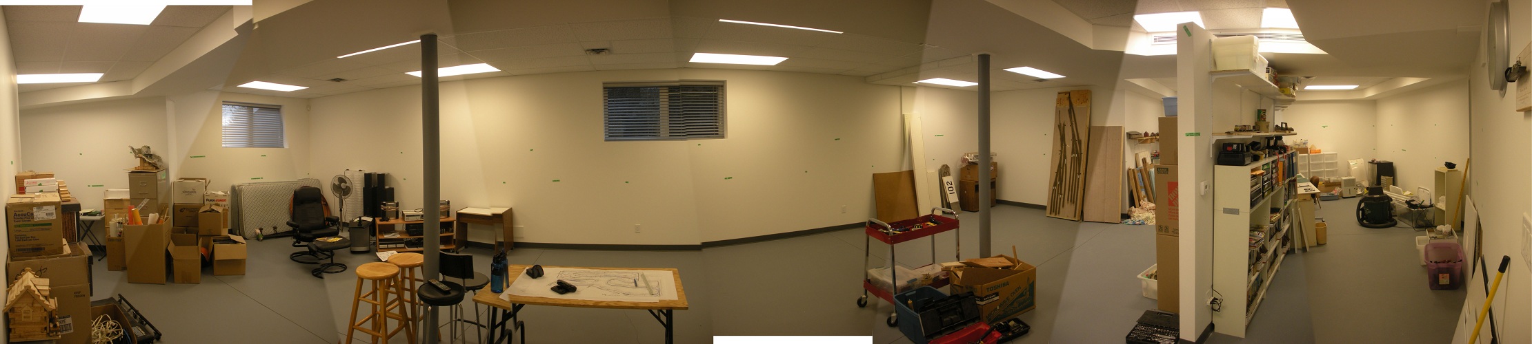
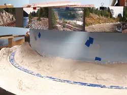
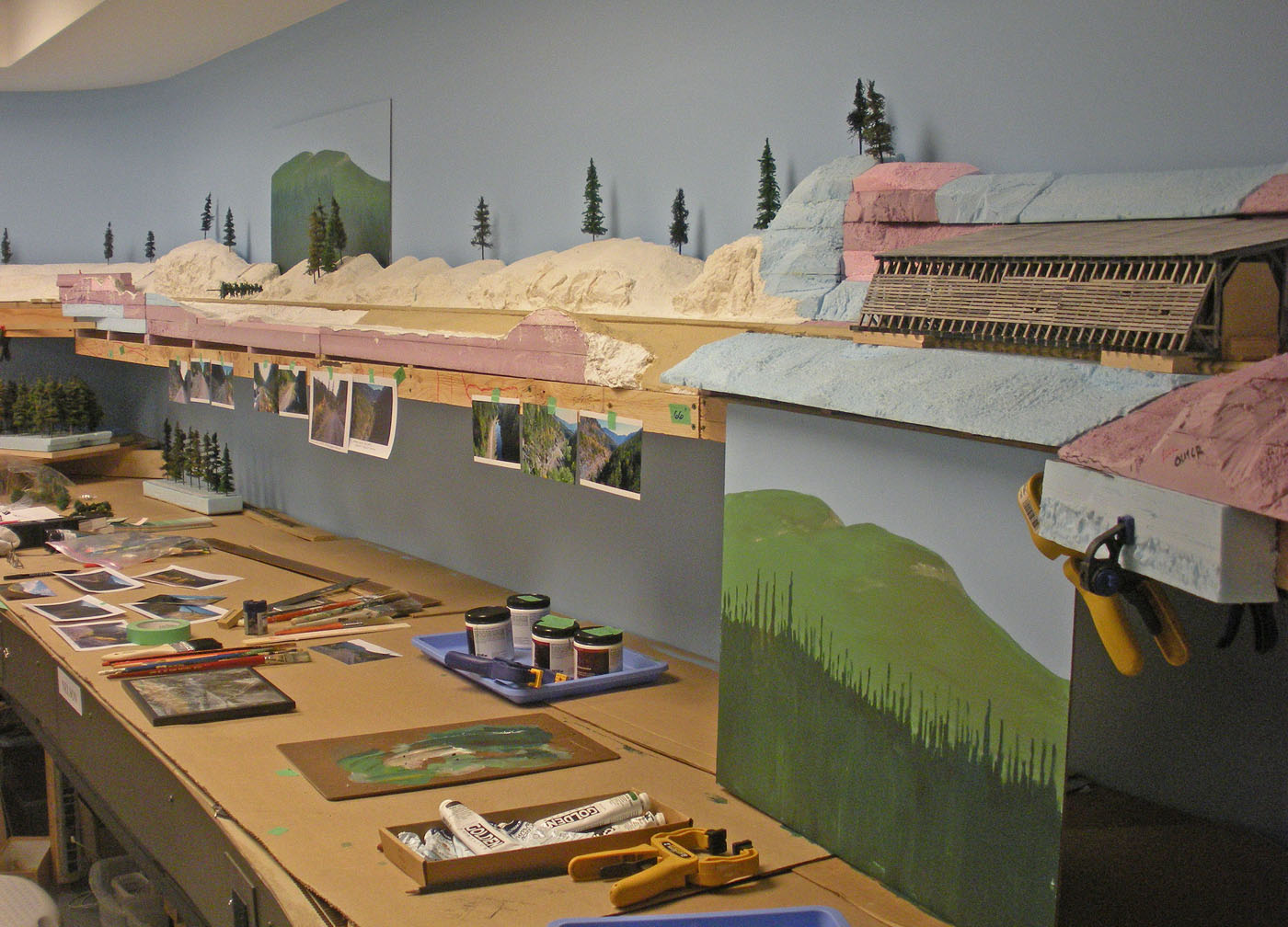
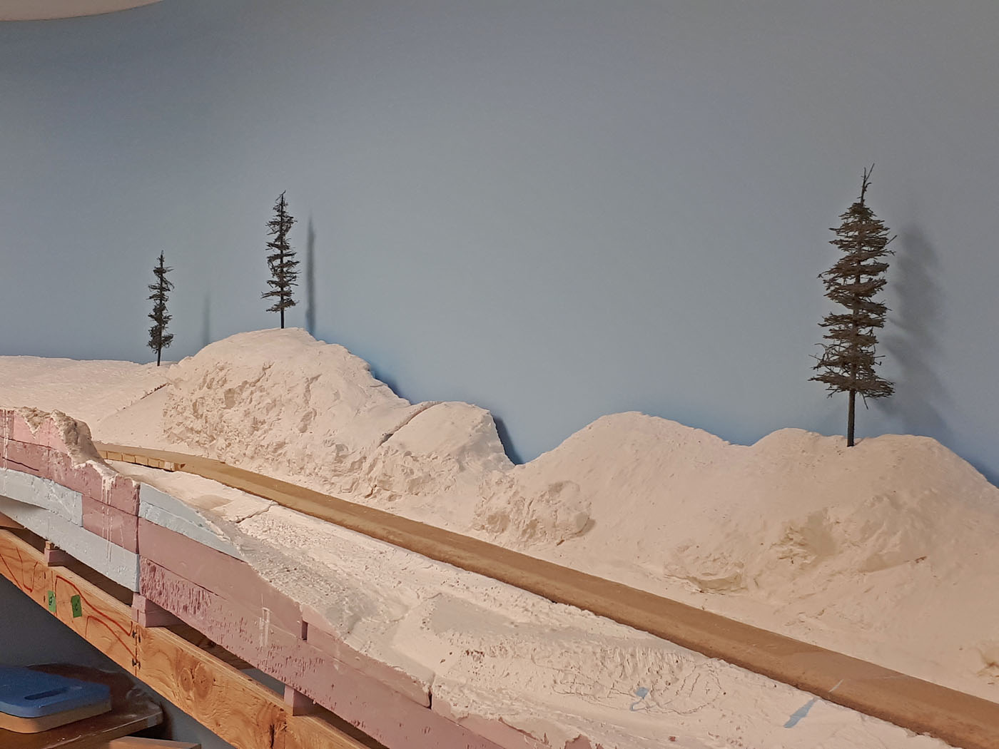
- Spring 2020 | CPR Boundary Sub
FarrON Scenery Underway
The Styrofoam scenery landform methods employed for the upper deck over Nelson yard have proven to be very successful, so we opted to continue using them for the Farron siding area through to the Porcupine siding area. See the Winter 2018 / 2019; Phase 3 of the Mainline Continues entry below.
-
In general, the topography of this area is far less rugged than it is through the section over Nelson yard, so preparing the Styrofoam landforms is proceeding more quickly, and it is anticipated to take a lot less effort to complete. This shelf is only 12” in depth to the back wall, except where the buildings are located where it will be about 18”. -
Work in this area also involved installing a backdrop along the 20 foot long wall behind the siding which was needed to cover over the metal shelving brackets mounted to the wall. -
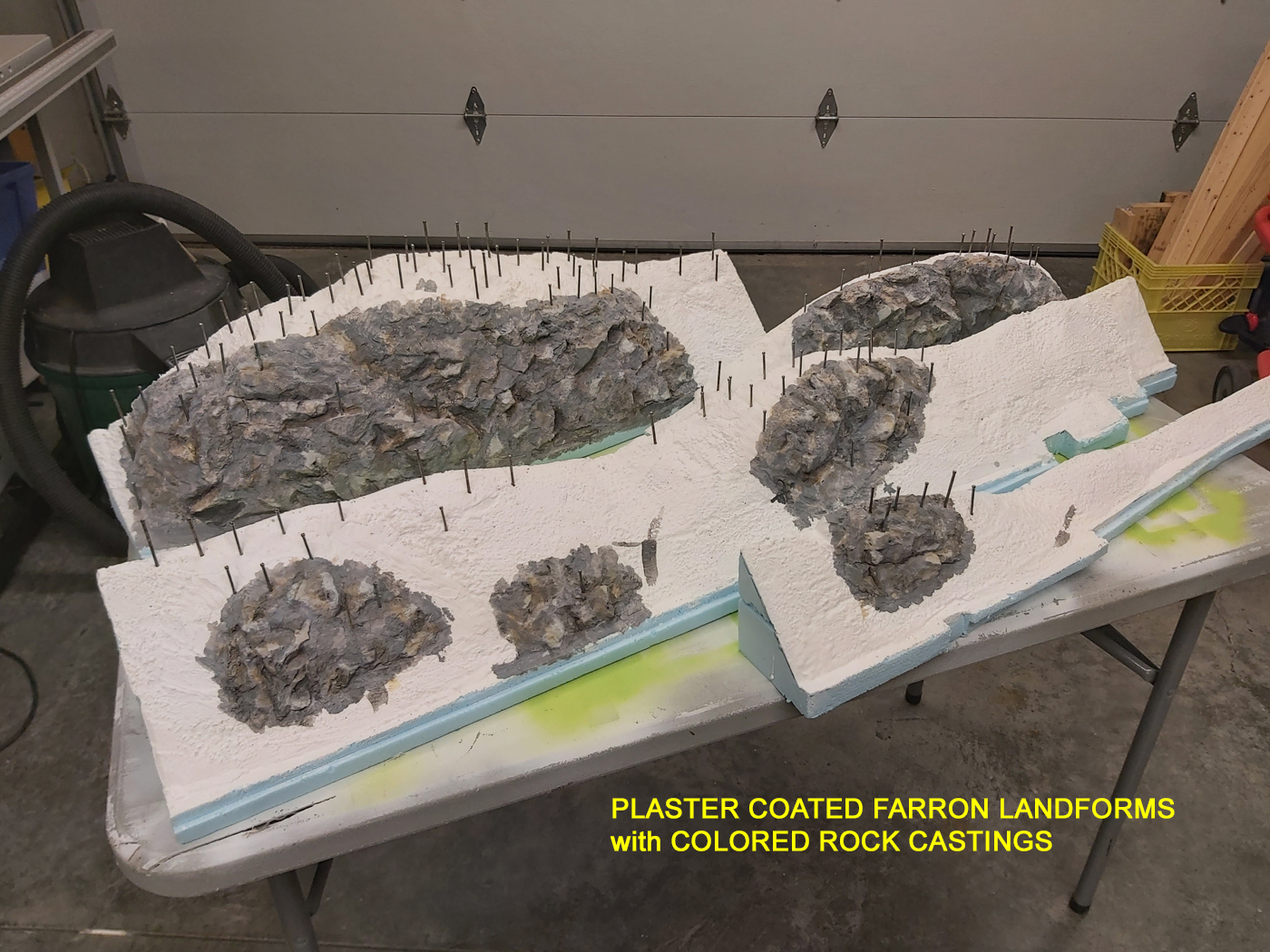
Most of the landforms have been completed using the variety of methods and tools utilized for previous work. As always, this is a messy process so the bulk of the work including completion of the basic ground textures is being done in the garage/shop and not the actual train room. -
All the scenic Styrofoam landforms are shaped and have rock castings and a base plaster coat on them. Although they are now ready for the detailed scenery textures and coloring, this work will now wait until I complete the installation of the switch machines for all the Farron turnouts. It is much easier to do that work when the scenery landforms are not installed. -
Here is a couple of “before” photos looking both east and west along the Farron siding area, and a recent panorama photo that captures both directions. 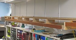
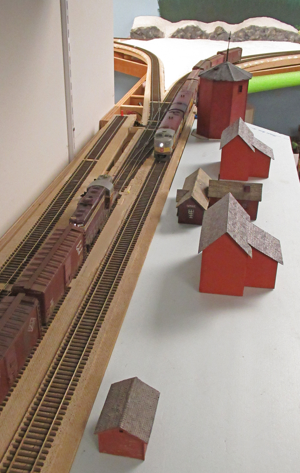
- March 2020 | CPR Boundary Sub
Farron Siding Structures
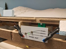
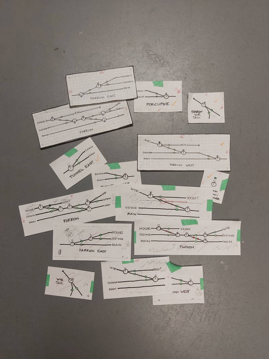
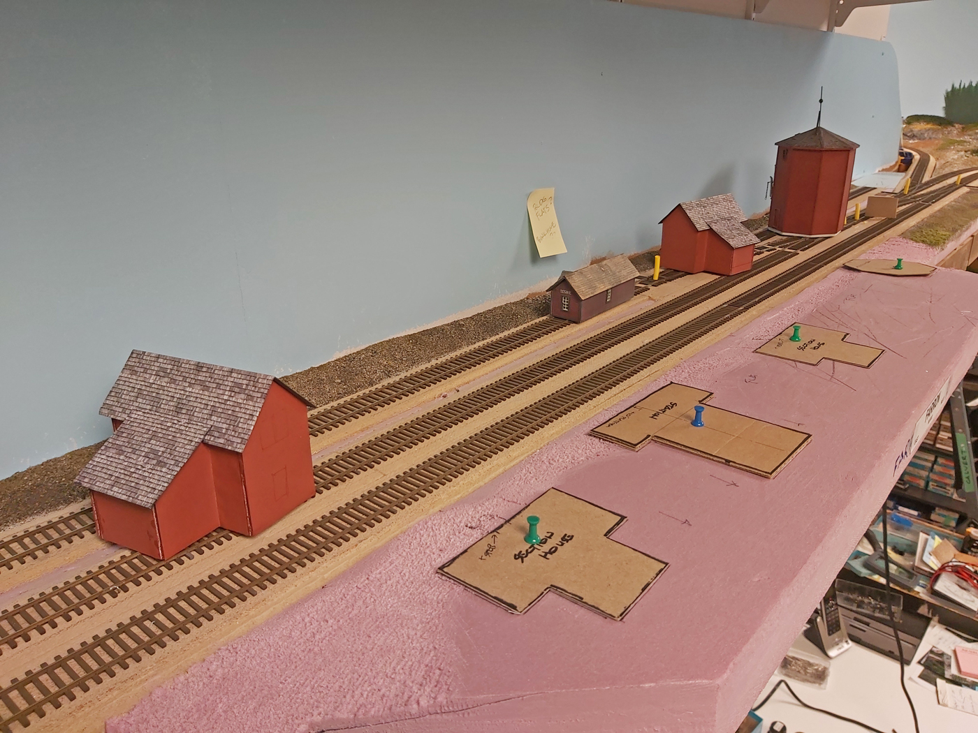
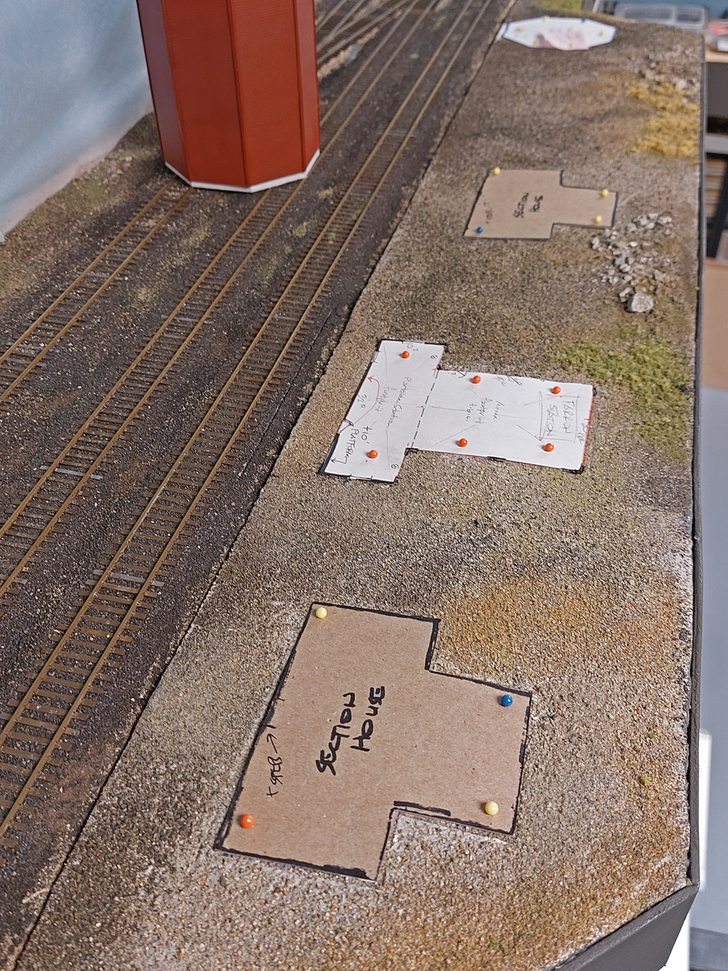
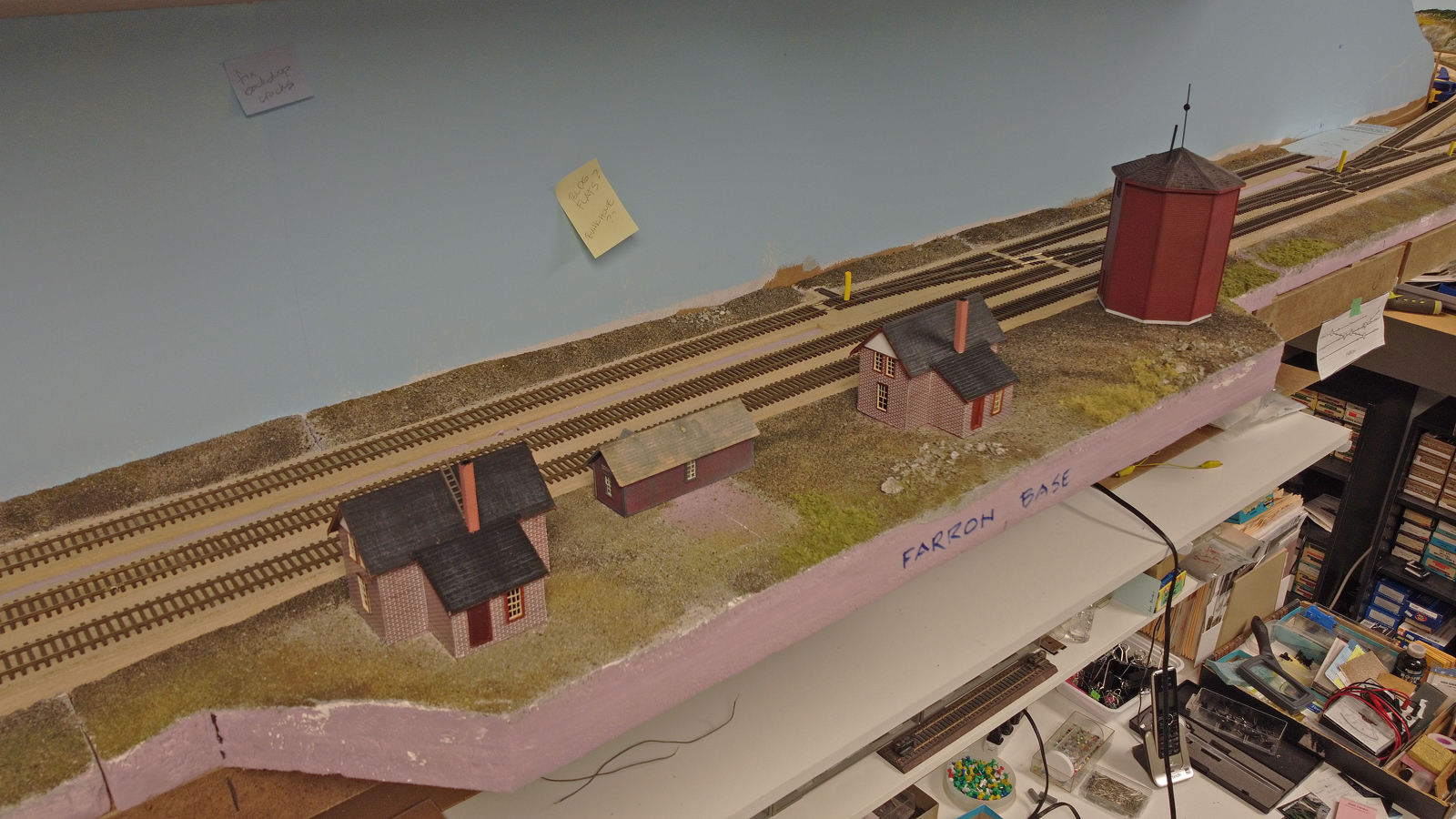
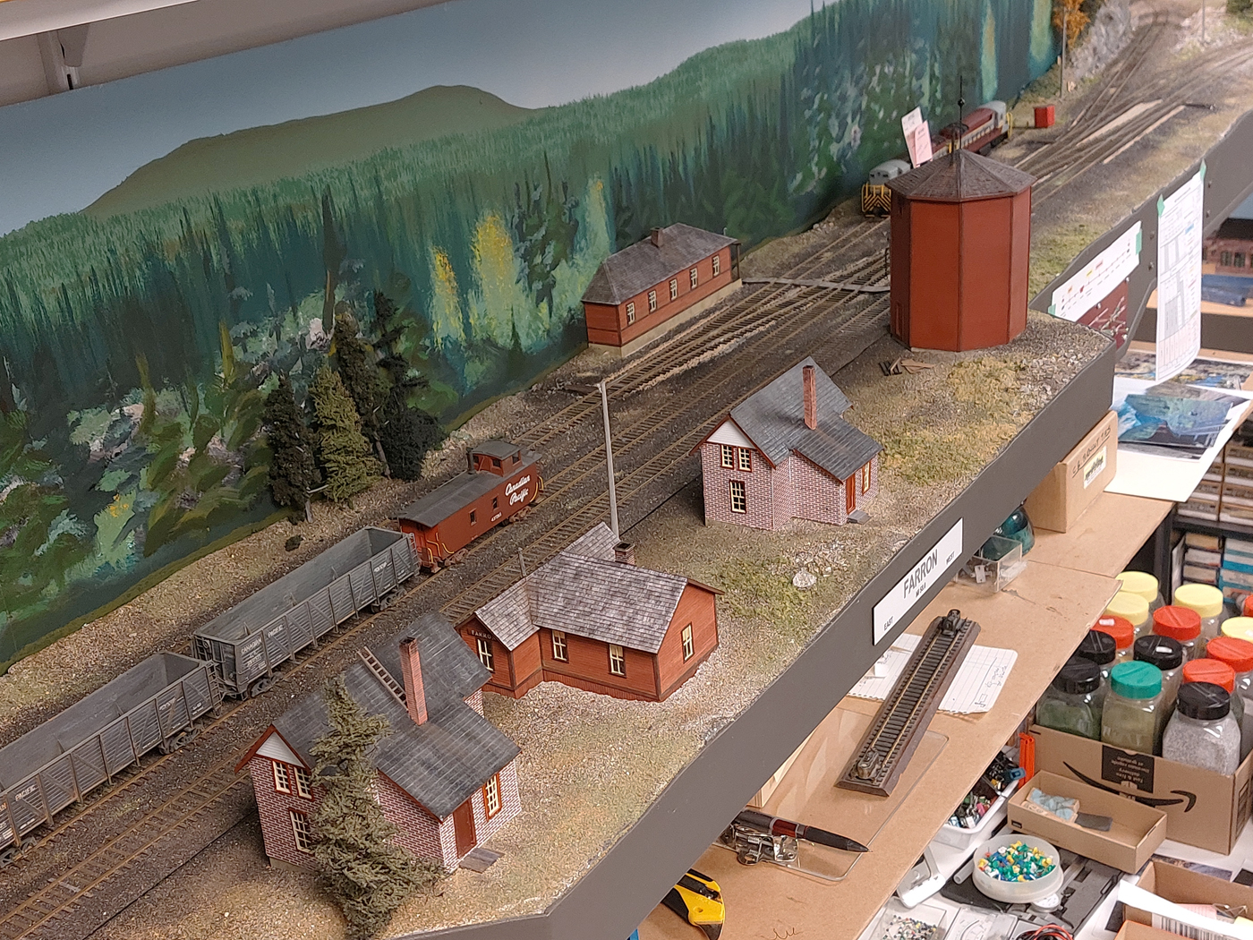
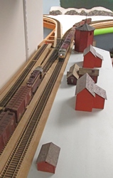
Farron is the summit station for the crossing of the Monashee Mountains and was home to the helper locomotives during the steam era. There was a variety of structures located here and in my era several remained in service.
-
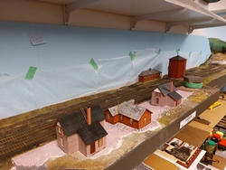
Our research is ongoing since photos of this somewhat remote location are not that common, however, we have ascertained which buildings we believe were there in the early 1960’s. Most of the structures were generic designs, although as is typical with the CPR, many of them were not built “exactly” to the standards! -
In conjunction with the planning and execution of the scenery in the Farron area, a mock up was developed with accurate mock ups of the buildings that were felt to be appropriate for this location. They will all be scratchbuilt, and at the time of writing, the 40,000gal water tank is nearing completion by Patrick Lawson MMR, who has been a frequent contributor of wonderfully built structures for the layout. -
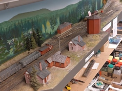
Here are a few photos of the construction of the mock up buildings and overall area;

- March 2020 | CPR Boundary Sub
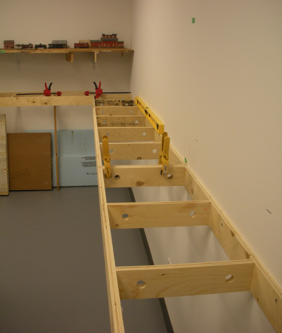
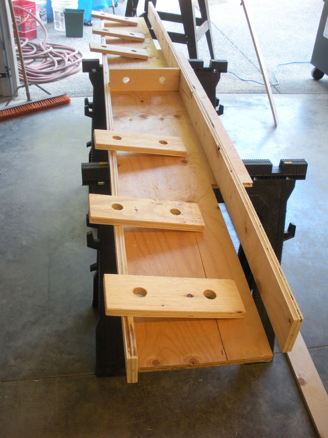
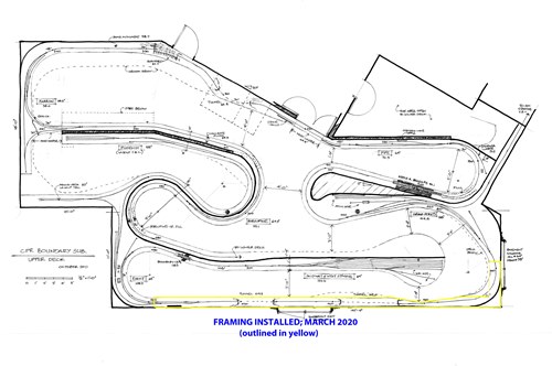
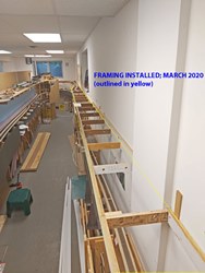
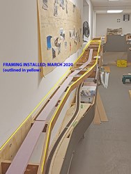
Upper Deck Framing; Grand Forks to Eholt
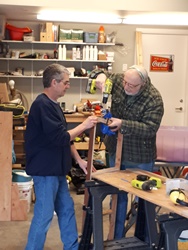
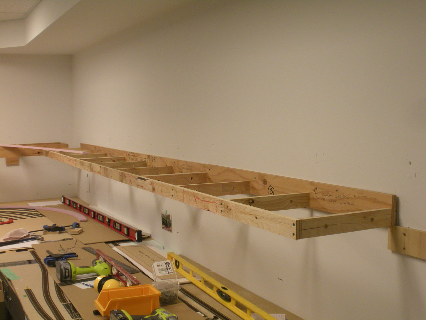
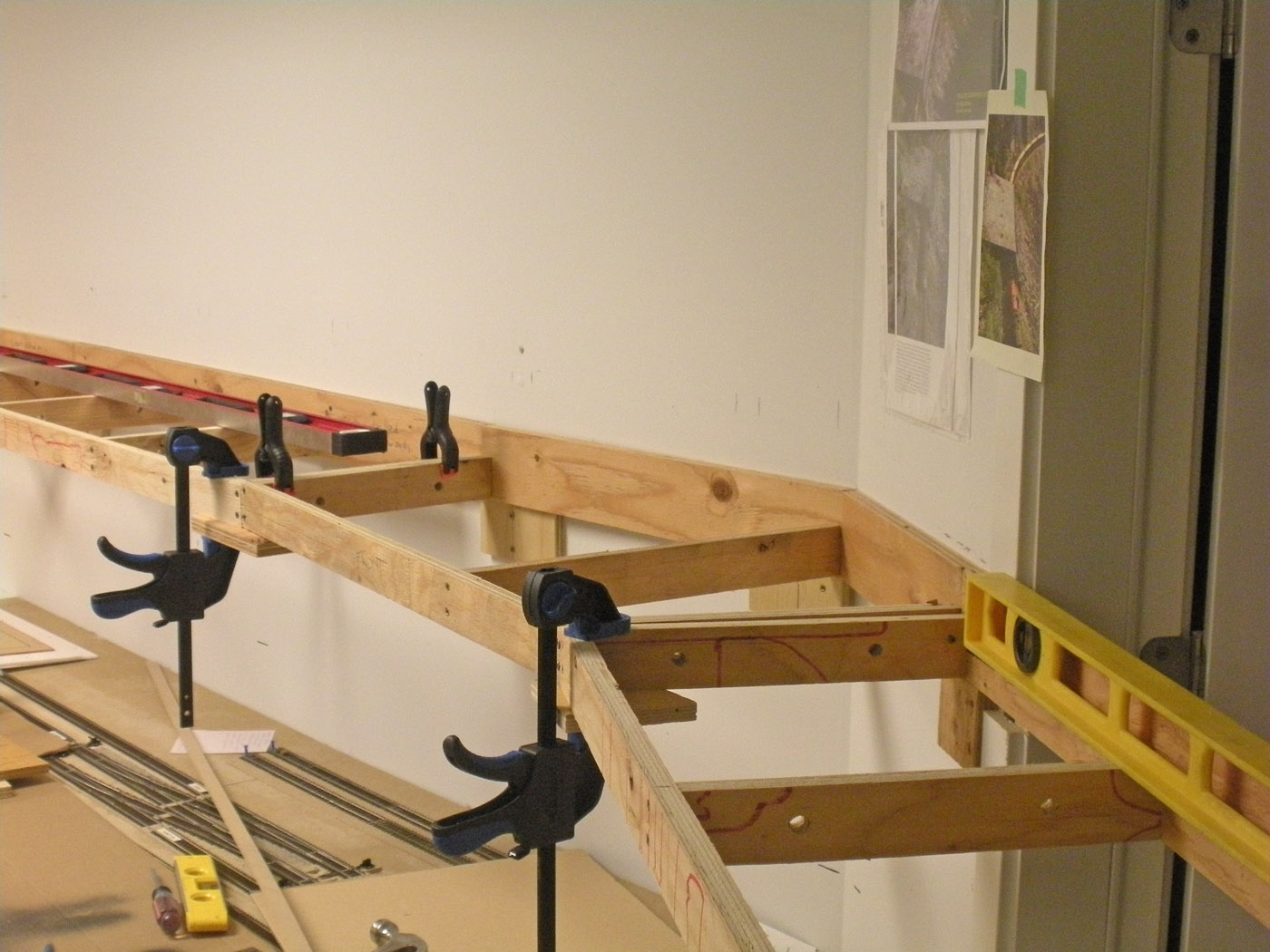
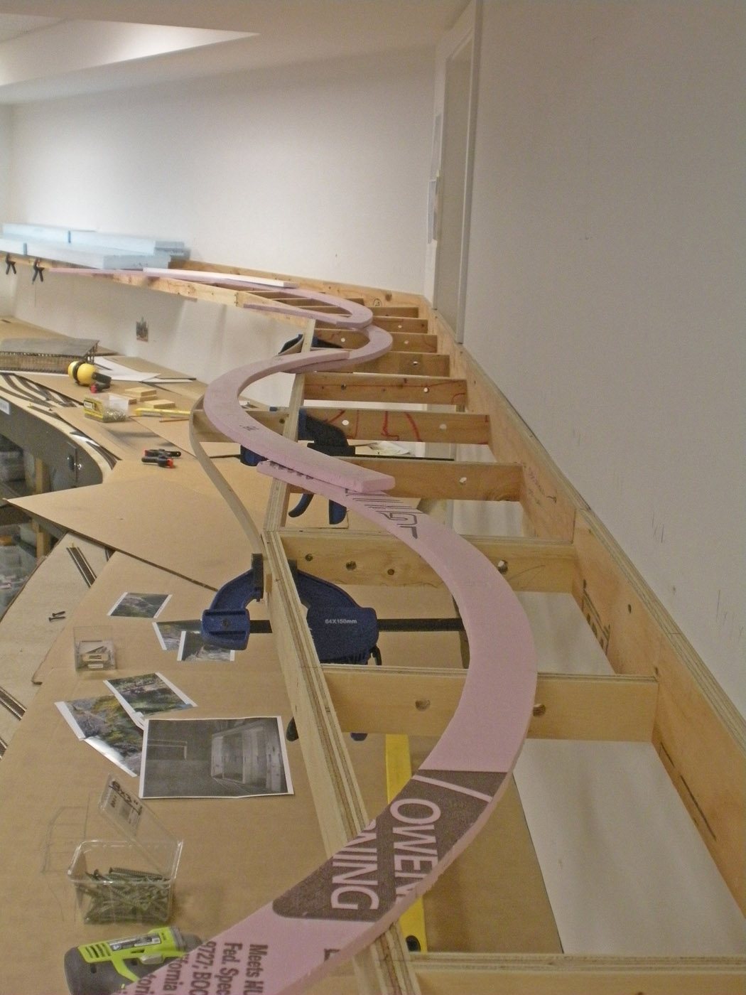
Since the scenery work is typically done by myself, when I have helpers attending my work sessions, I create other projects to capitalize on their availability. After completing the west end staging modules referred to below, we then shifted to the construction and installation of a series of pre-fab plywood modules that would connect Grand Forks to Eholt. This is actually the longest straight section of upper deck on the layout at about 45 feet in total length.
-
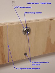
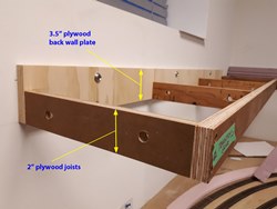
Once again we utilized our successful pre-fabricated plywood module framing system for this section. Most of the modules are the typical 12” x 48” long with a few custom sized ones at the narrower area and all have predrilled wiring holes in them. To maximize clearance to the lower deck and provide some depth for the scenery below the upper track, 2” deep joists and a 3.5” back wall plate were used. Because the track grades are 2% on the lower track and a lesser 1.25% on the upper track, we needed to step the modules up at a couple strategic locations along this stretch of framing to maximize clearance to the lower track. -
Like the west staging yard referred to below, this framing will simply remain in place for the time being until more detailed design work is completed and the actual mainline trackage gets closer. Depending on how the next phase of the mainline expansion gets executed, we may remove 3 of these modules and drop the existing temporary west end staging yard modules in their place which will add the locations of Fife and Grand Forks into the layout, and extend the mainline by another 75 feet. -
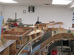
Here is a layout plan showing the extent of this new framing, and a few photos. The pink Styrofoam pieces indicate the rough alignment of the mainline.

- February 2020 | CPR Boundary Sub
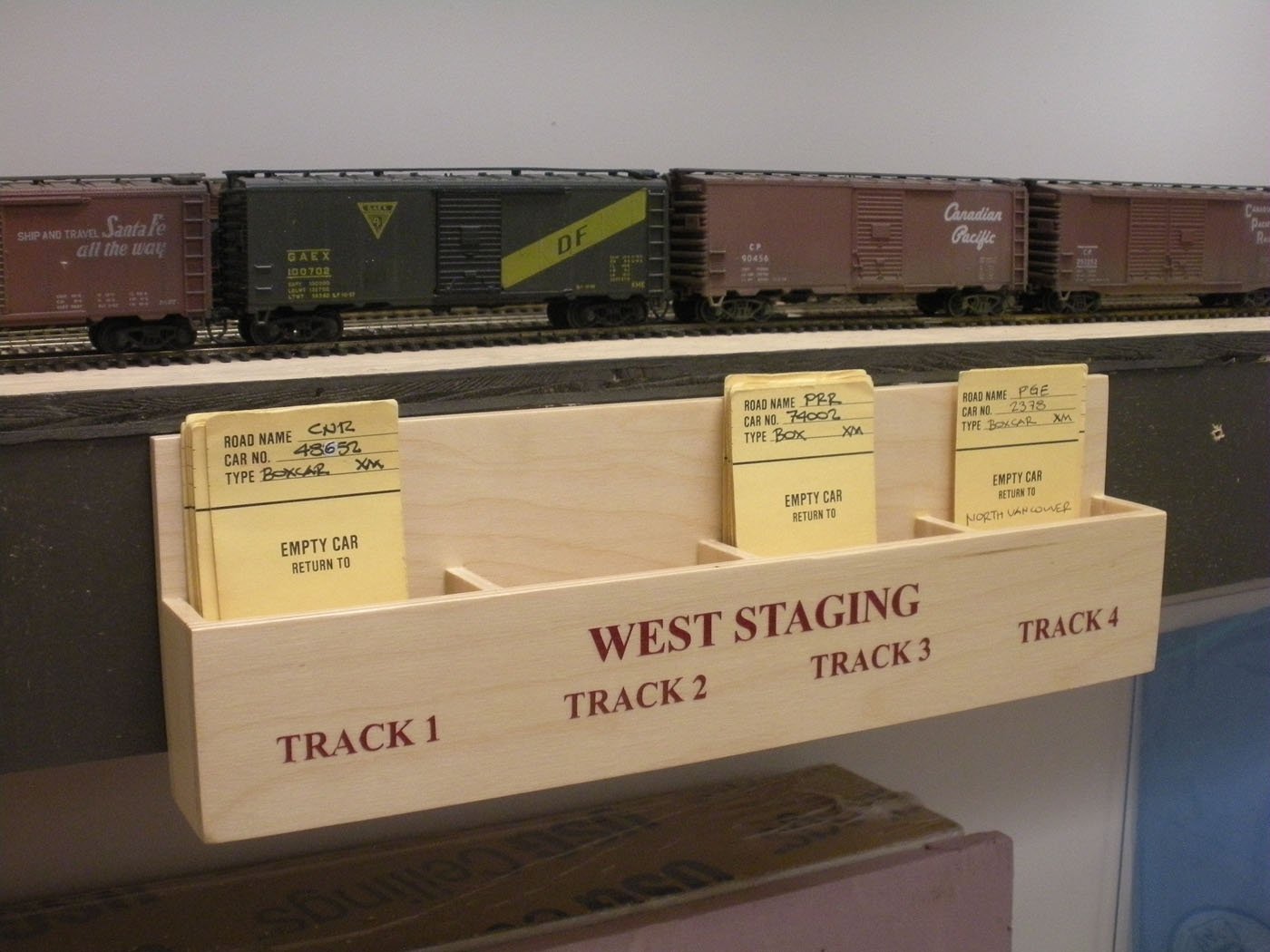
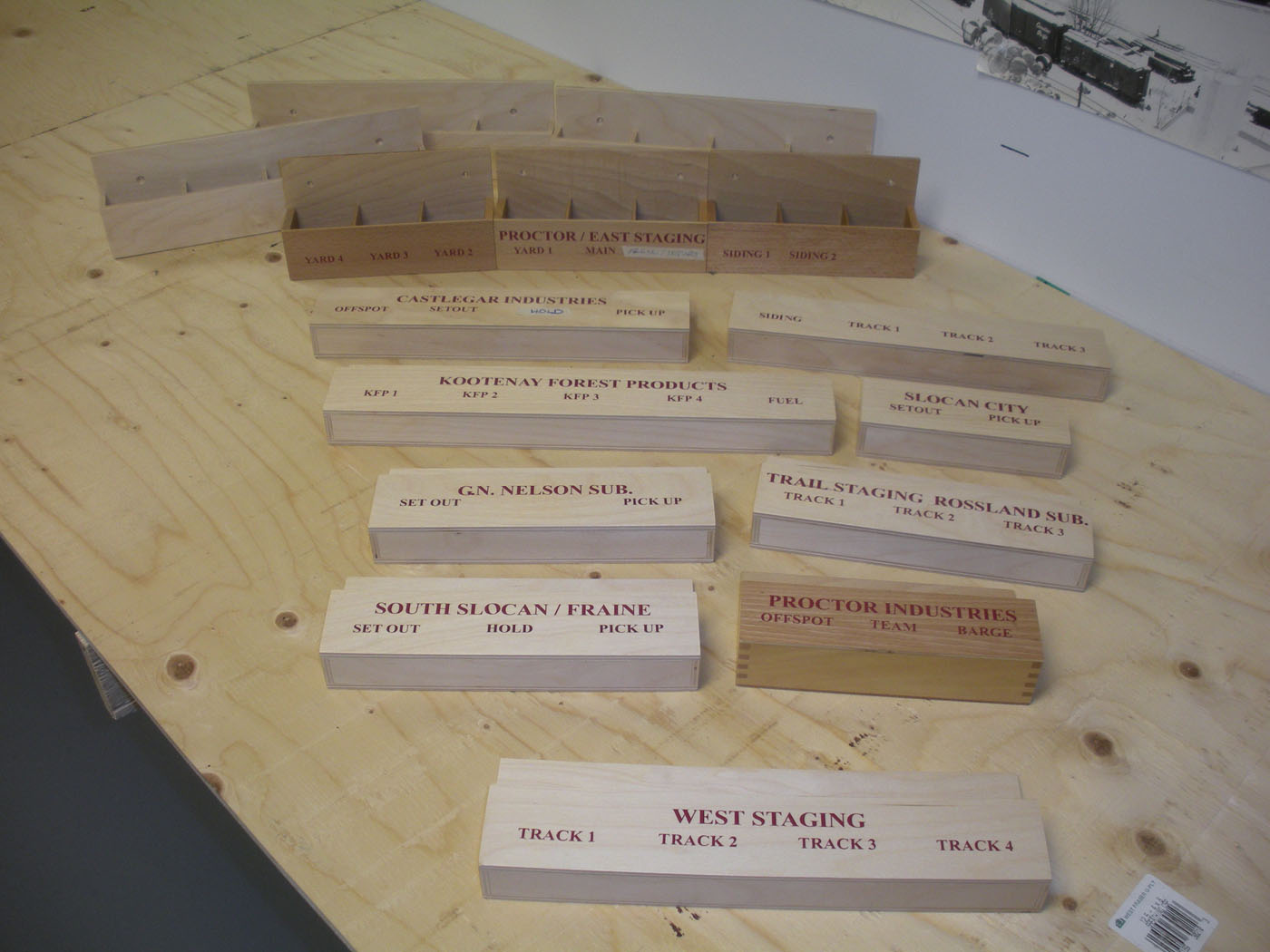
West Staging; Latest Concept
When I designed the layout originally in 2011, I admit I didn't invest much thought into the final west end staging yard design. The initial concept was simply to expand the Midway divisional yard at the west end of the layout to include a bunch of staging tracks, and it was left at that.
-
In the last couple of years, as the mainline continues to progress westward, I have started to initiate planning for the final west end yard. Over the last several years, a couple of concepts have been developed through sketch plans, and subsequently abandoned for various reasons.
-
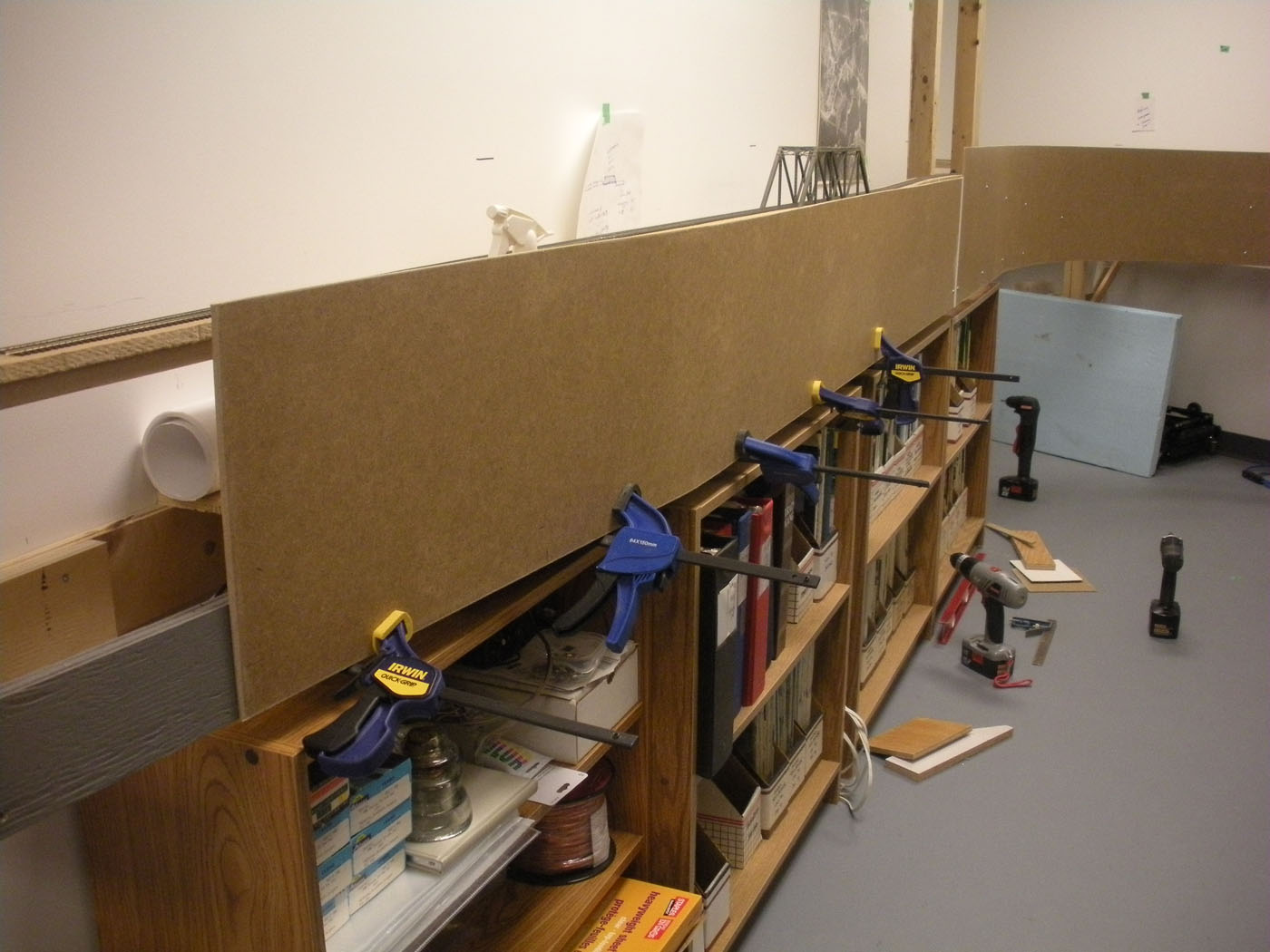
In late 2019 while wandering around the train room and brainstorming, I revisited the issue of planning the west end staging yard – again, and came up with yet another idea. After sketching up some framing and track alignment concepts and theorizing how the trains would work and scenery might develop visually, we jumped into more detailed design, construction and installation of several of our pre-framed plywood modules.
-
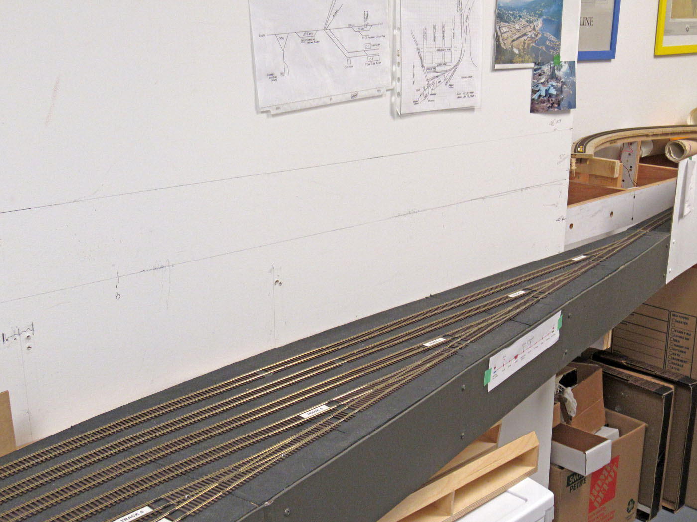
With the assistance of Ken C and John M, we managed to get 3 modules temporarily installed which will hold 7 tracks and with a capacity of about 200 cars.
-
-
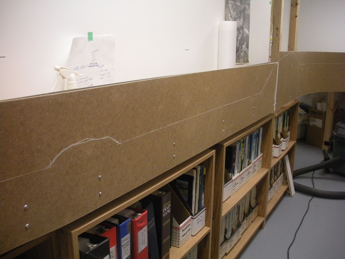
Since there are two more expansion phases containing the remaining 180 feet of mainline required to reach the west end staging yard, these modules will remain in place for the time being, while we continue with other priority projects. This allows us to ponder if this will be the actual “final” design.


-

- August 2019 | CPR Boundary Sub
Completion of Phase 3 Mainline Trackwork
It was imperative to complete this phase of the mainline in time for the bi-ennial Vanrail Operations weekend taking place on Sept 6 to 8th, so we had to really hustle to achieve this objective. As described in previous postings, we were well into the construction of this next section of the layout as the deadline became closer; however, a lot of work remained to do in just a few brief months!
The scope of this project included; completing the construction of the framing modules, constructing the spline roadbed system from the end of the previous mainline up to the location of the relocated staging yard, designing and constructing a vertical lift bridge to span over the room entrance door, preparing and installing all the turnouts and flextrack, installing the necessary bus & feeder wiring, and then testing everything. Before relocating the west staging yard modules, as much work as possible needed to be completed and tested. Much of the work employed the same successful techniques used to date on the layout which certainly helped move things along.
There were some stressful moments; however, with the substantial assistance of Ken C and John M, we made it – barely!
Here are a few progress photos of the work as it proceeded.
-


- August 2019 | CPR Boundary Sub
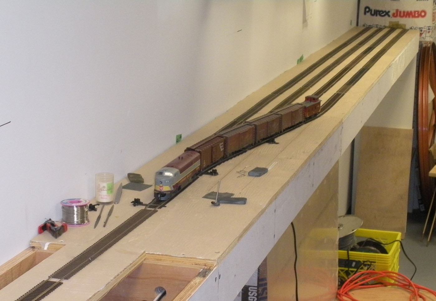
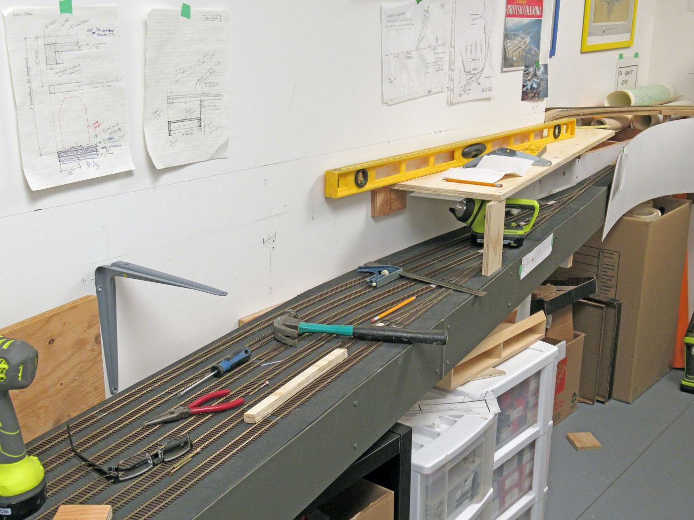
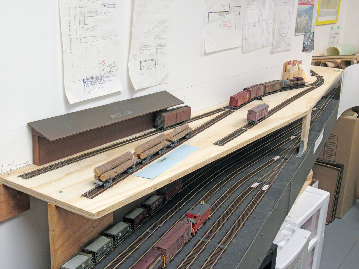
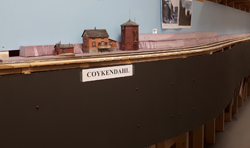
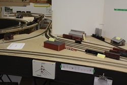
Temporary Slocan City Module
Over the years that we have operated the layout, I have observed that folks running the Slocan Turn switching train often got frustrated due to the limited amount of track at that location. The design of the layout contemplated another section in the dispatchers room that was to represent Slocan City and the Slocan Lake barge operation. Even though this section of the layout had not yet made it to the top of the action list, I decided I needed to construct at least a temporary section of this future area to provide some relieve to the congestion that occurs there.
So, with only 1 week until the VanRail Ops event, I grabbed a 1ft x 8ft piece of plywood and spent the day designing and constructing this temporary switching area that connected to the South Slocan wye tail track. I reused the temporary cardboard buildings and faked out a barge location for now. While not very fancy, it certainly reduced the problem and folks that were assigned this job during VanRail appeared more relaxed. This section will be removed in the future when the final design is completed for the Slocan City area.
Here are a few progress photos of the work.

- Summer 2019 | CPR Boundary Sub
Upper Deck Scenery Continues
Work on the upper deck scenery continued as long as possible before the need to stop and clean up the layout and uncover Nelson yard to prepare for the test operating session on August 28th, and ultimately the VanRail operating sessions. My thanks go to Rene Gourley who took on the last minute job of painting the backdrop in this area based on the numerous photos I had taken over the years – including numerous drone photos.
The actual scenery efforts were a continuation of the materials and methods we started using on this deck back in the fall of 2018. All scenery landforms are stacked Styrofoam sheets carved with various tools, to which plaster rock molds were wet cast and remaining areas were covered in a plaster seal coat. The rock castings were colored with a variety of diluted acrylic and latex paint colors and the non-rock areas were painted with a base ground coat of latex paint. Then a huge array of scenery materials was applied using many photos as a guide.
The installation of trees and foliage was left until the landforms were placed back in their positions so the height and colors of the foliage could be matched to the painted backdrops thereby creating a more blended appearance.
While not completed, the result of this work was visually impactful and, again, provided lots of learning moments!
Meanwhile, here are a few photos showing some of the efforts to date. Also, please refer to the Layout Photos tab for many more photos of this work to date.


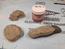
- June 2019 | CPR Boundary Sub
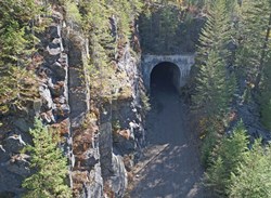
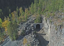
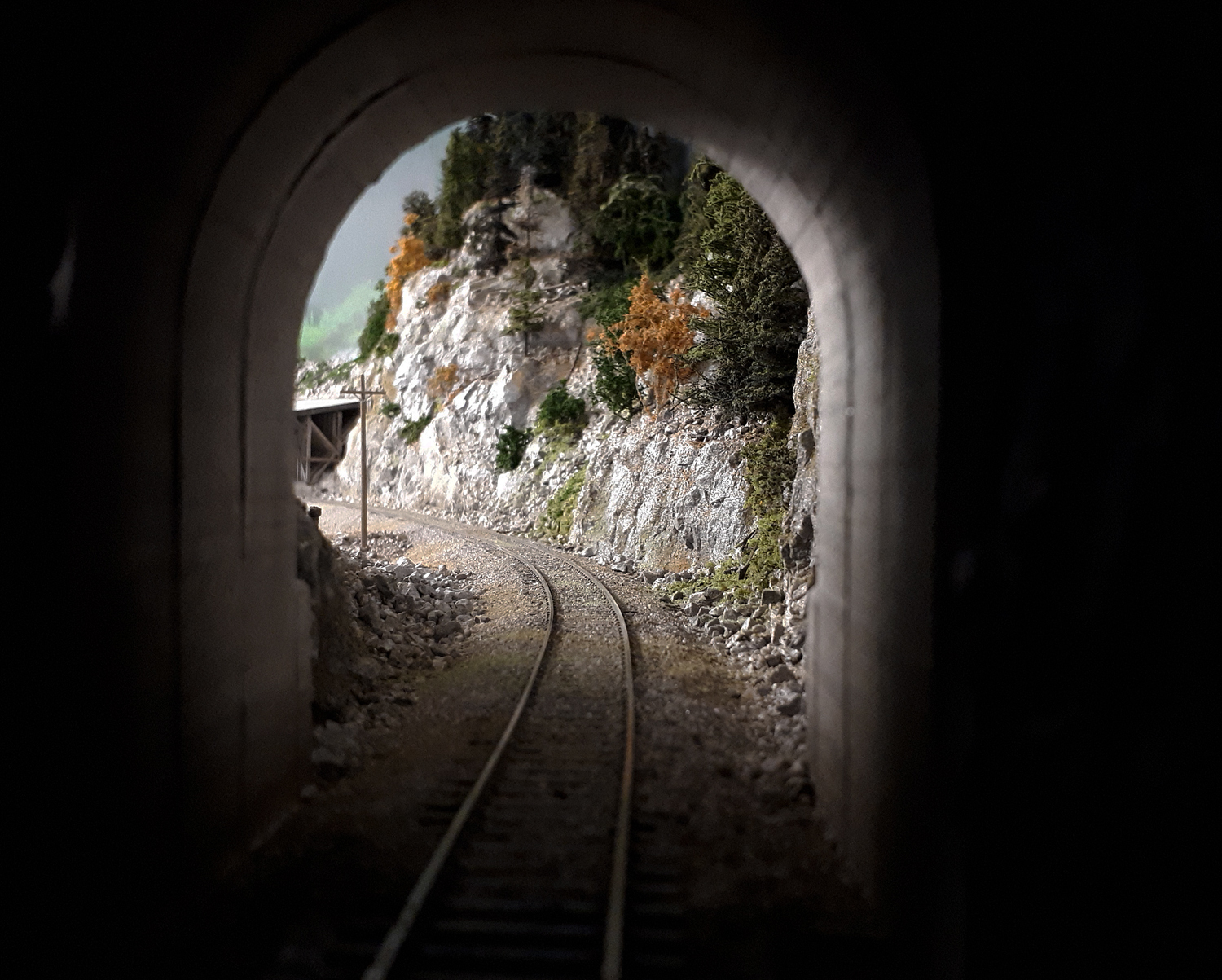
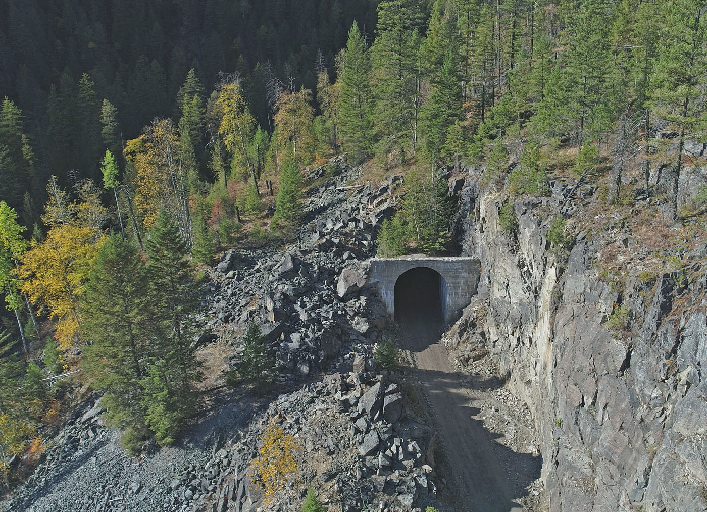
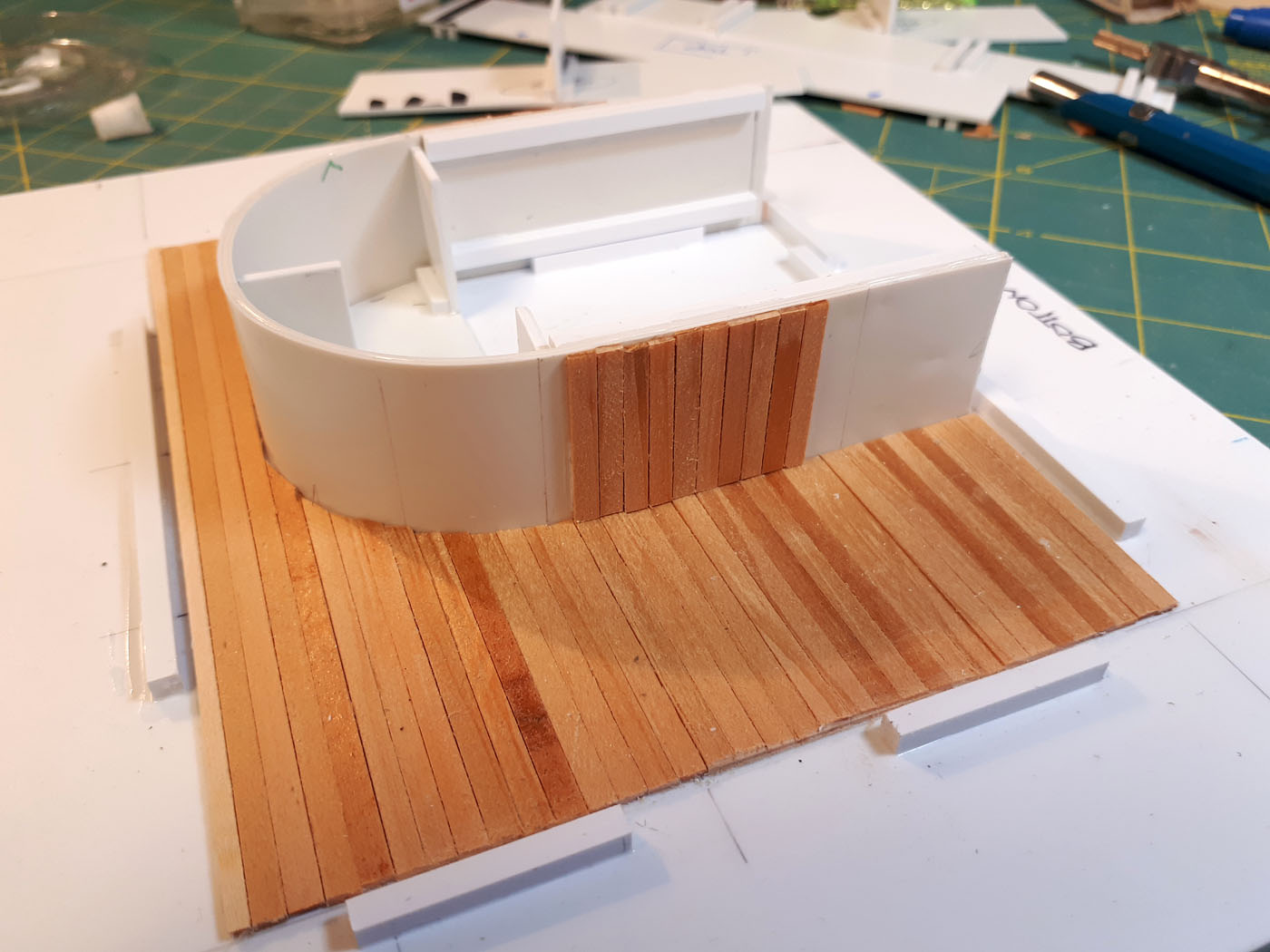
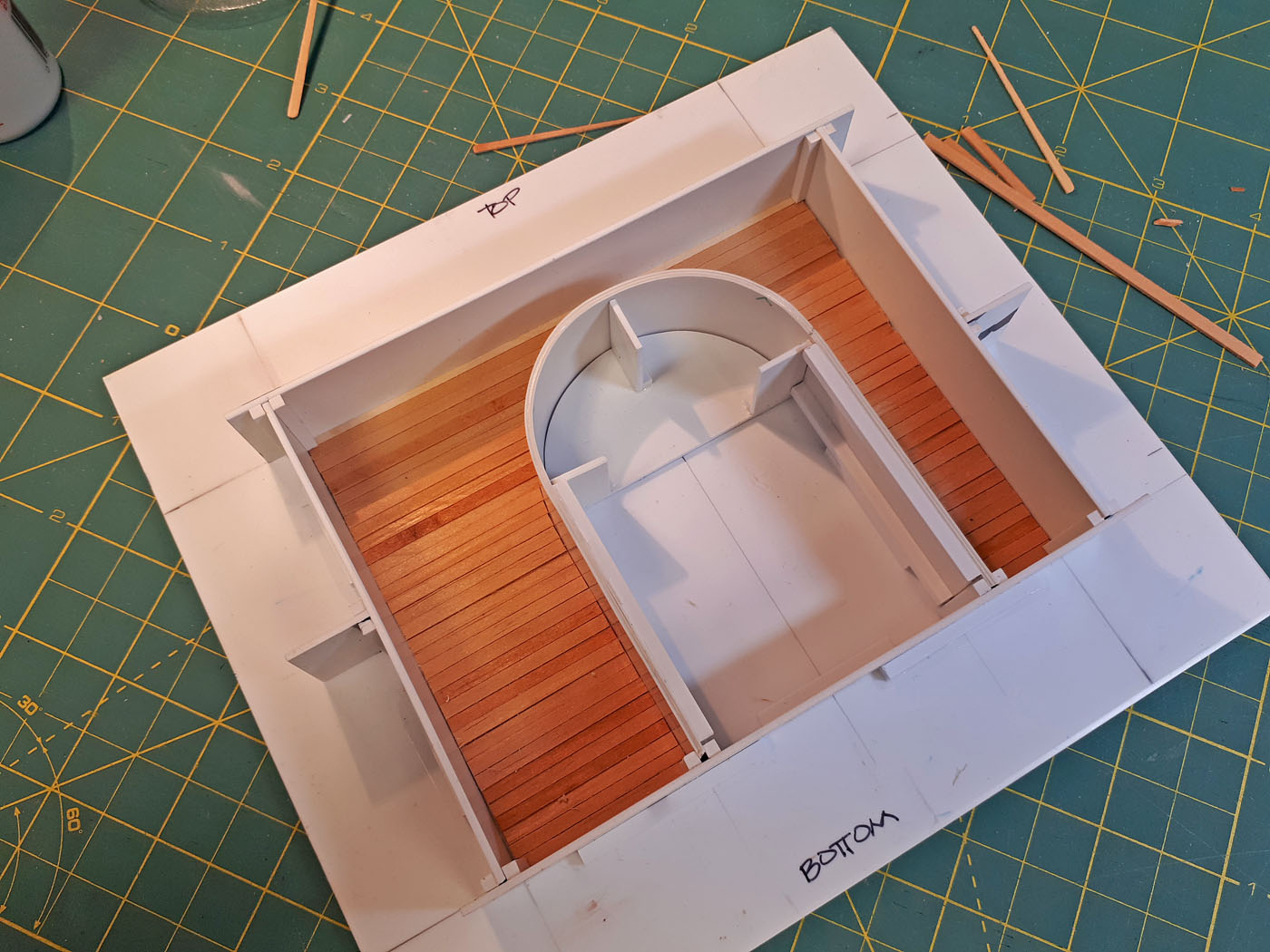
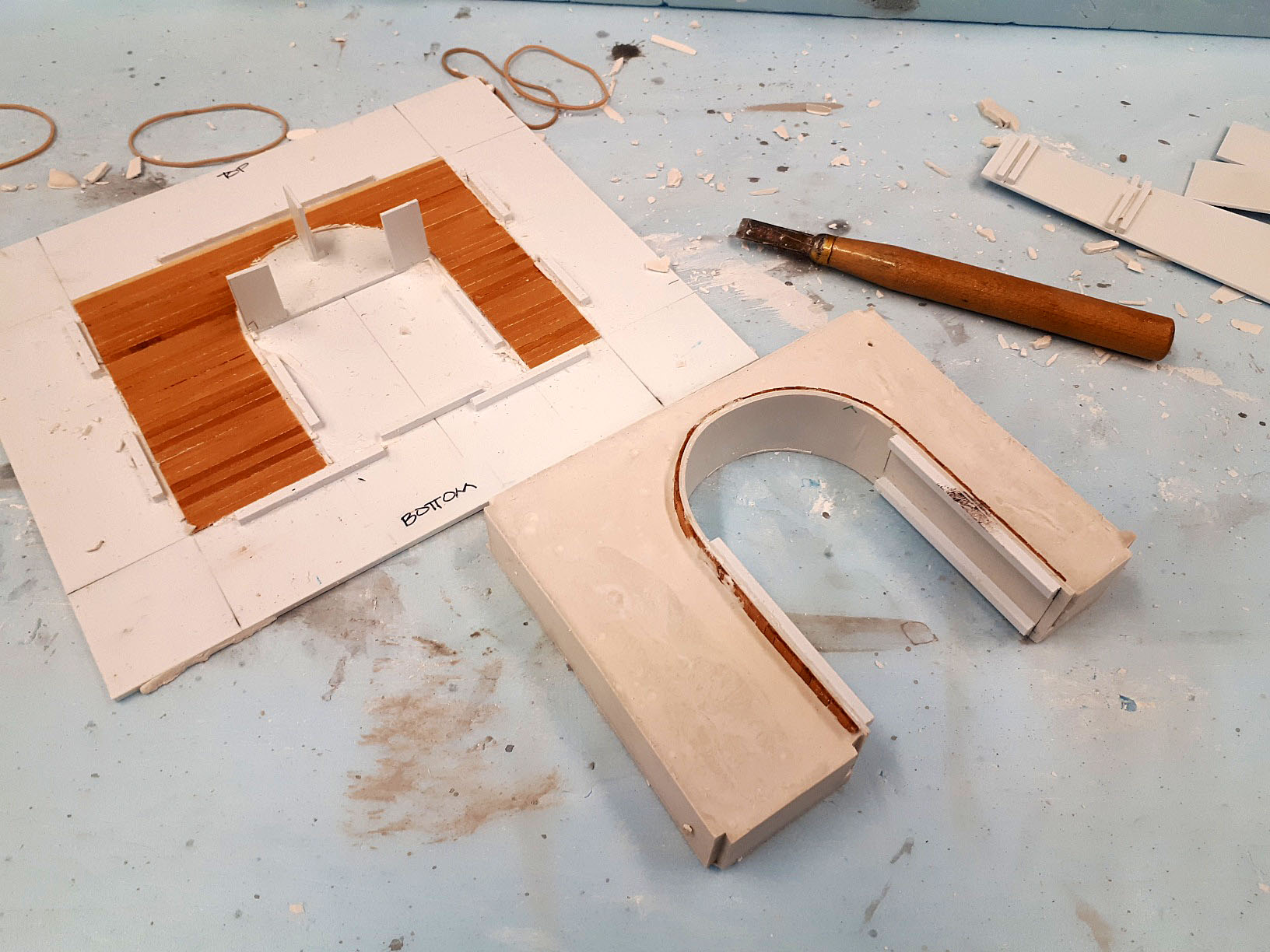
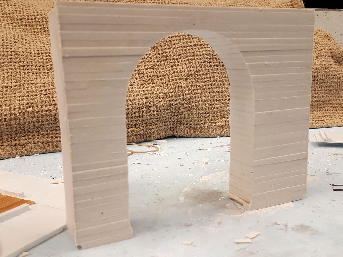
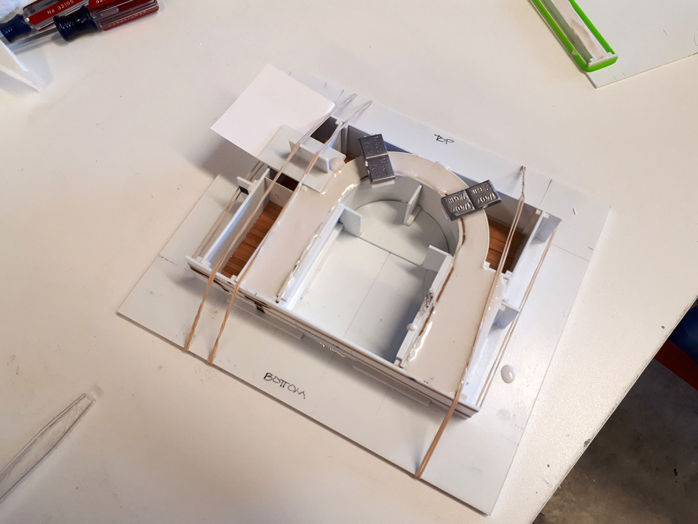
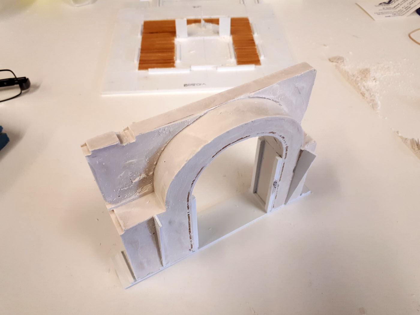
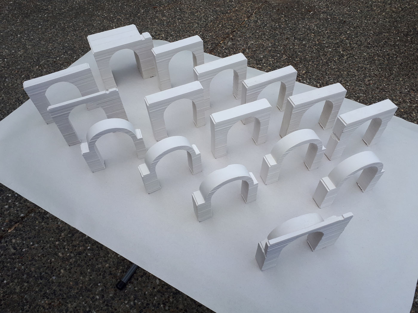
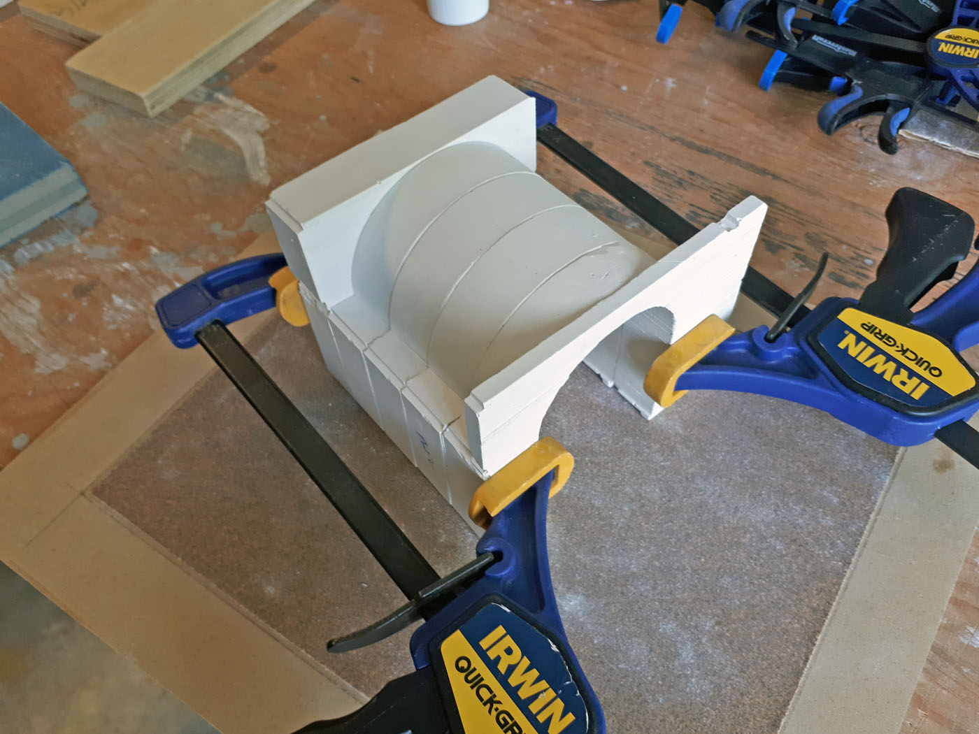
Concrete Tunnel Portal and Liner Castings
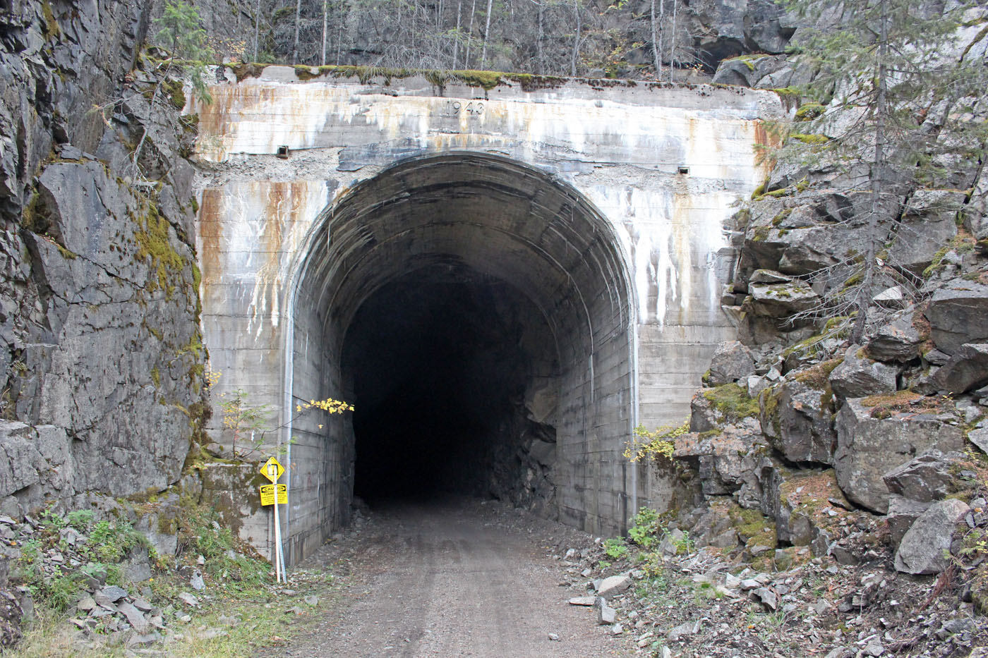
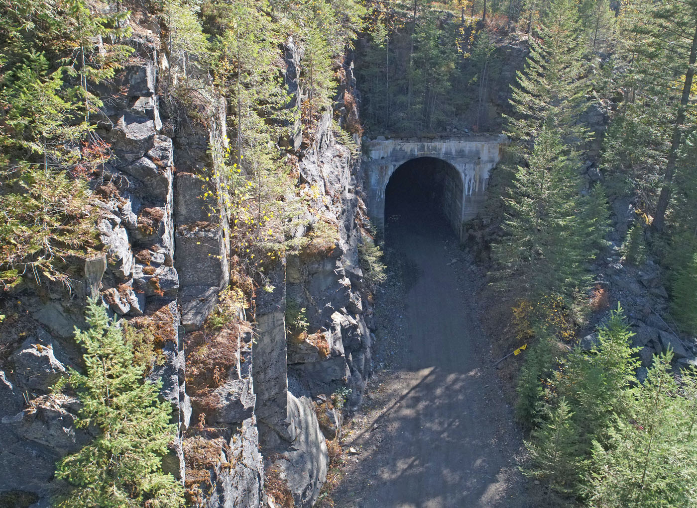
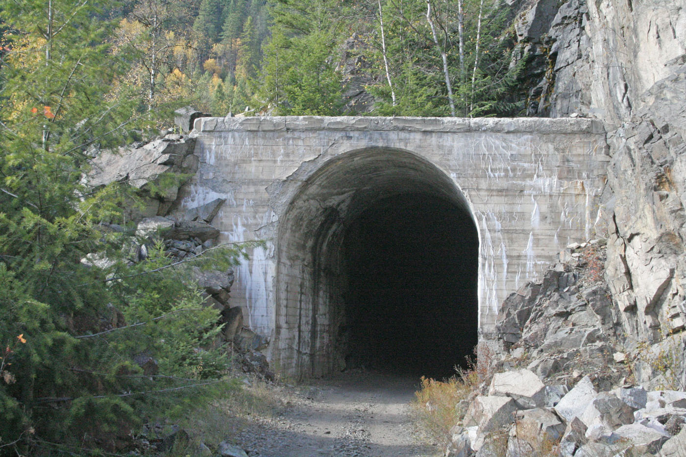
One of the key features of the current mainline expansion is the 365 ft long curved Paulson tunnel. While originally constructed as a rock bore in the late 1800’s, in the mid 1940’s both ends of this tunnel were reinforced with concrete portals and liners. In addition, there are few other tunnels on the Boundary Sub. that have concrete portals. While they are all somewhat unique, they do have some geometric similarities. There are no commercial model castings that even come close to emulating the prototypes so I designed a plaster casting mold that had variations in it to capture the shapes of the prototype portals. The mold is lined with rough scale lumber to give the finished castings a formed wood look. In order to create the look of the concrete liners, several castings were sanded and then grafted together to achieve a liner depth that reflected the prototype. In total, I cast 18 castings altogether, which will be sufficient to complete all the Boundary tunnels with a couple of spare castings – just in case!
Here are prototype photos of the two Paulson tunnel portals:


And here are photos showing some of the many steps and resultant castings:
-
- Winter 2018 / 2019 | CPR Boundary Sub
Phase 3 of the Mainline Continues
Further to the July 20, 2018 post below, here is an update regarding the ongoing construction of this phase of layout expansion.
So, after spending a couple days clearing out Nelson yard of all rolling stock, locomotives and structures, the entire yard surface was covered in heavy cardboard to protect it and away we went!
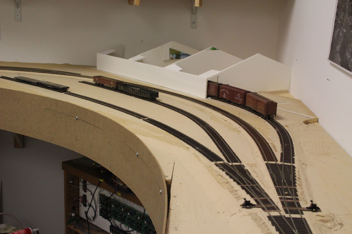
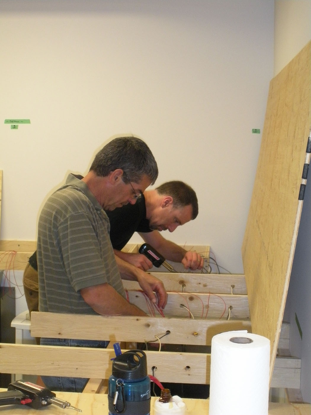
Numerous “module” frames were constructed to carry the mainline over Nelson yard. Other than the back 3.5” high piece, all framing was 2” high – ¾” plywood to minimize the depth. The prefab modules were typically 48” long and were constructed in the garage/shop and then anchored to the walls. This is the standard method of construction for most of the cantilevered framing for the layout. Here are a couple photos of the framing being installed. -
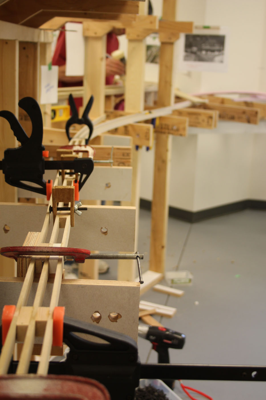
From there we utilized the Styrofoam roadbed templates to establish the track alignment on top of the modules. Once we were satisfied with that, we constructed the spline roadbed system (see Sept 2012 entry below & the clinic presentations in the Techniques tab) along most of the 40 foot length above the yard. This section is on a descending 1.1% grade, which is slightly more than half the prototype grade in this area. Here are a few photos of that part of the work;
-
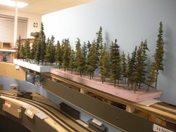
In an effort to manage the weight of these “modules” we elected to build the scenery landforms from Styrofoam in sections that aligned with the module joints. At this point we (ok – maybe it was just me!) were still thinking that the individual modules could be removed from the walls and do most of the scenery and track work in the garage/shop. After removing and replacing one of the smaller modules, it became obvious that taking them out and putting them back was going to require a lot of realignment to obtain successful re-installations, so, we (ok – it was me) abandoned the idea of removing/reinstalling the modules, but retained the idea of building the Styrofoam landforms separately, also in the shop. This turned out to be a very solid decision and has proven very practical. These landforms were built of stacked foam sheets glued together and then carved with various tools. I tried a hot wire cutter, and was not happy with the fumes or how it actually worked – so, I gave up and used a variety of knives instead. Here are some examples of the work to date;
-


-
 Once satisfied with the general topography of the landforms, they were given a coat of plaster and then rock castings were wet-applied in various places. The landforms were then placed back on the layout and tested for clearances and for visual acceptance. We are working to replicate several scenes along this part of the mainline as photographed on previous trips, including drone photos – see the October 2018 and 2017 entries below. This has been a very iterative process and some landform sections were deemed unacceptable and were salvaged to practice rock coloring on.
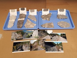
-
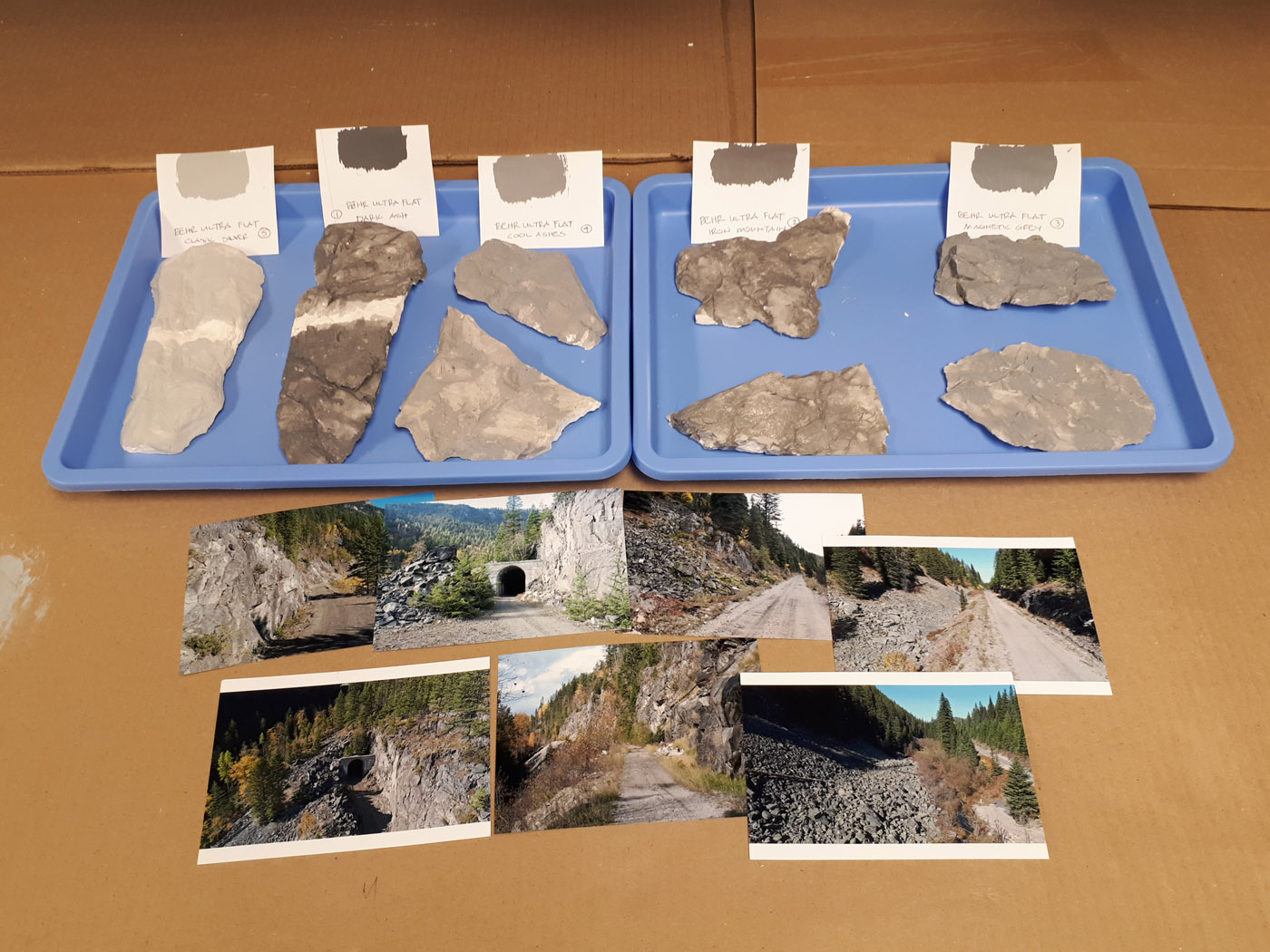
In the midst of this, I decided some more appropriate rock molds were needed, so brought home several dozen rocks to make molds from. This was somewhat disappointing project, and only about half the molds turned out to have the nature of rockwork I was looking for. The natural rocks in this part of the Kootenays are what I refer to as “chunky” and many commercial molds do not capture this type of rock. In any event, we managed to get several good molds, and combined them with the old ones I had and some that were lent to me. We did try the Woodlans Scenics rock molds which have some very nice texture, however, we found they too stiff and not suited for the wet casting techniques to do.
-
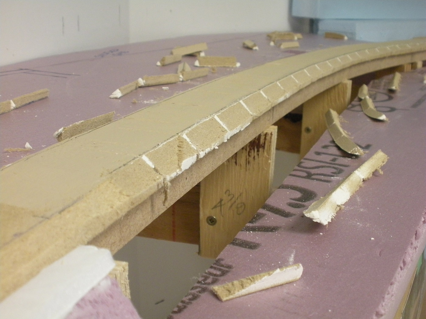
We decided to accurately lay out the track centreline on the roadbed next, trim the edges of the roadbed to create the side slopes, caulk all gaps and give the roadbed 2 coats of latex paint. We felt this would be much easier to do without the landforms in place. Here are a couple photos of those steps;
-

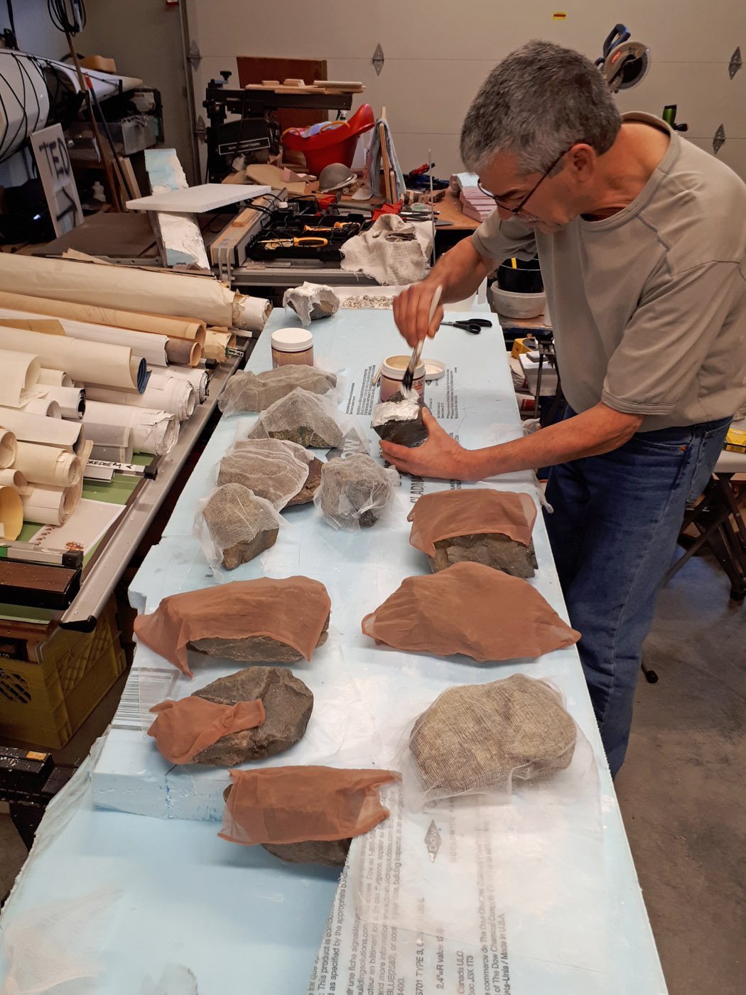
Meanwhile, I realized I had not done finished scenery in over 6 years – not since the previous layout was demolished – and it seemed I forgot a lot of what I learned back then! So, I decided I needed to spend time on techniques, coloration etc. on extra castings before applying my efforts to the real landforms. It has been a painful process, with lots of mistakes and less than satisfactory results, however, I think I have learned the rock color techniques now – remember, I am trying to model very specific scenes so what I refer to as “colors and textures” are important. So, with some trepidation, I am now cautiously embarking of rock coloring on the permanent scenery landforms. Here are numerous photos showing some of the efforts to date.
As you can probably imagine, this all takes a fair amount of time considering this section is about 40 feet long and is quite complicated from a scenic perspective. Consequently, the work is still underway, although we are getting close to be completed the Styrofoam landforms and plaster work can conclude in the near future. And, all of this work was undertaken at the same time as the Paulson snow shed – see post below – was being constructed! -
-
So-stay tuned for the next installment where I will hopefully be able to share some more completed scenic photos and backdrop progress!
- February 2019 | CPR Boundary Sub
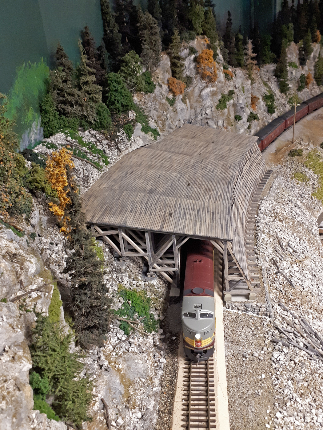
Paulson Snow Shed Completion
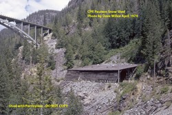
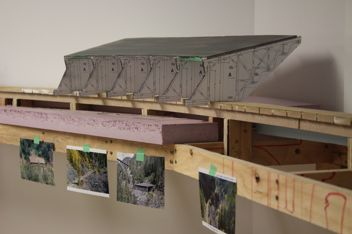
This shed is located in the Paulson area on a 2% westbound grade and is the larger of the two on the Boundary Sub. It was planned for a signature location on the upper deck that is currently under construction and therefore needed to be constructed as part of that extension project.
-
It is located on a curve and is about 165 feet long. I believe it was removed sometime in the 90’s and replaced by an electronic slide detection fence.
-
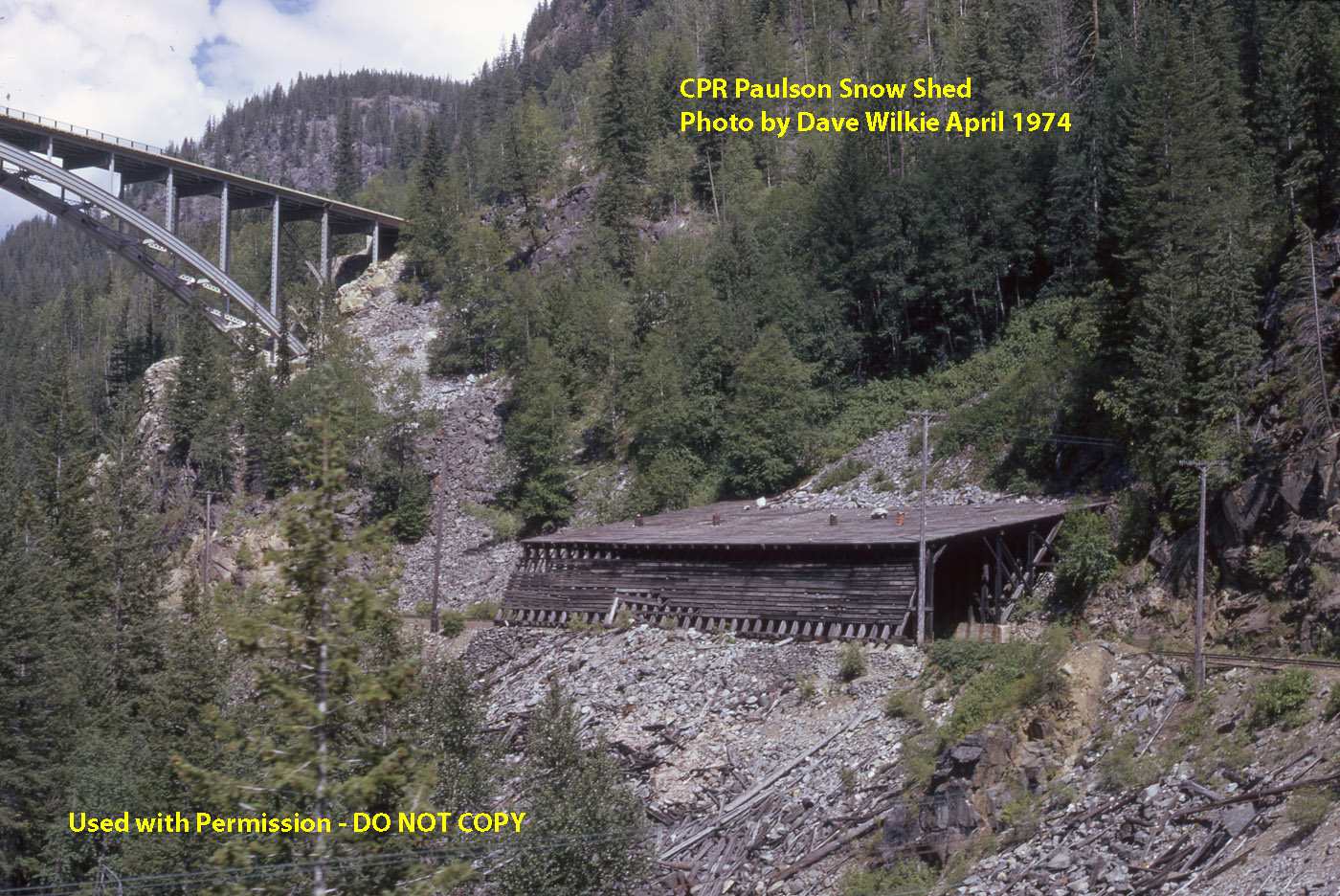
I wanted to scratchbuild this shed and make it as close to prototype as possible, and was fortunately able to secure some great photos of it taken by the late Dave Wilkie in the 60’s and 70’s. These were very important in providing guidance on what aspects of the shed did not follow the standard CPR design and also its physical condition in my era.
-
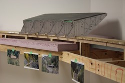
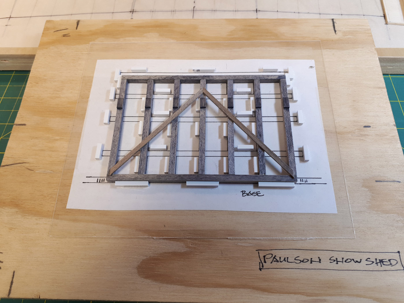
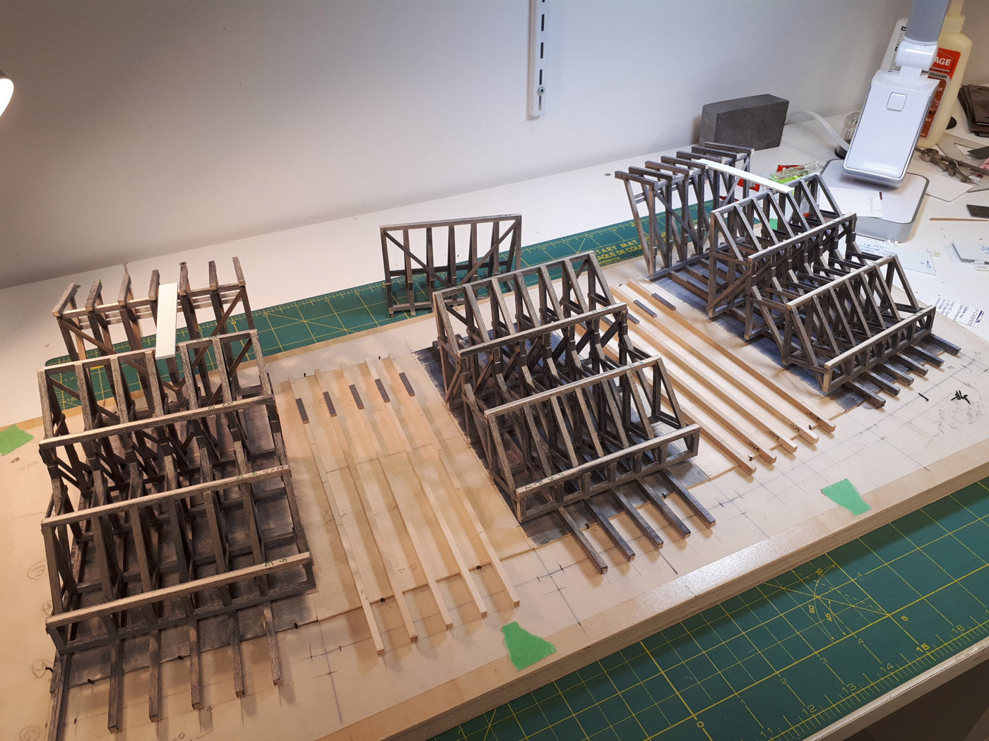
I decided to construct the shed in 5 equal tangent sections and to build it upside down – so, first thing was to make a template of the track alignment and for the shed itself. It straddles a 59” R curve on the layout. Once I had these, I made a foamcore mock-up of the proposed structure so I could test fit it as the layout construction continued. Here are a few photos of this phase
-
Satisfied with the overall geometry, I amassed a lot of stripwood and sheet stock to build the shed. I used 2 different strength mixes of black show dye and isopropyl alcohol to stain all the stripwood before using it in the structure. I opted to stain the sheetwood used for the roof after it was installed to mitigate any warpage issues. I also investigated the quality and accuracy of several makes of stripwood before deciding on Mt. Albert materials.
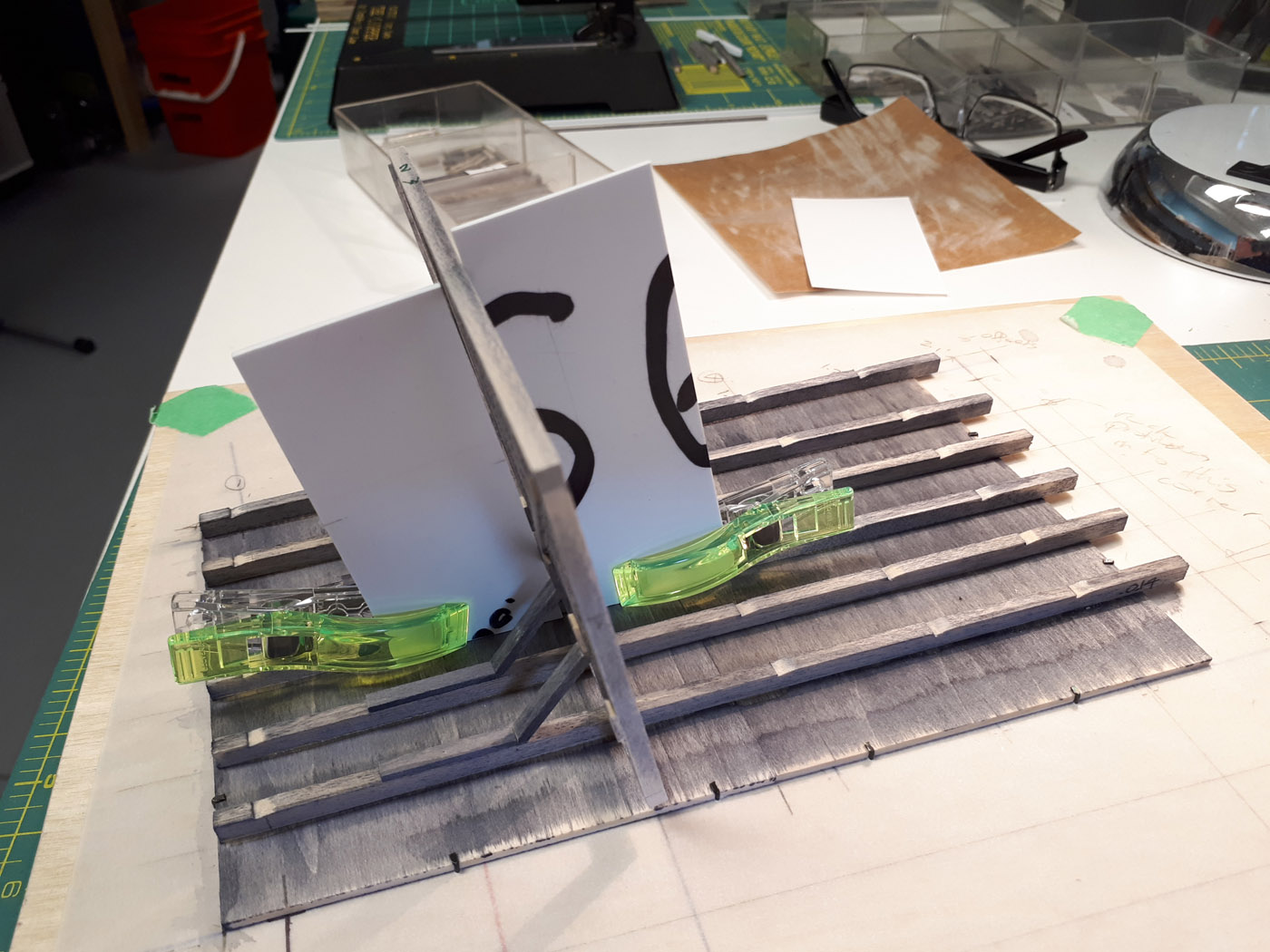
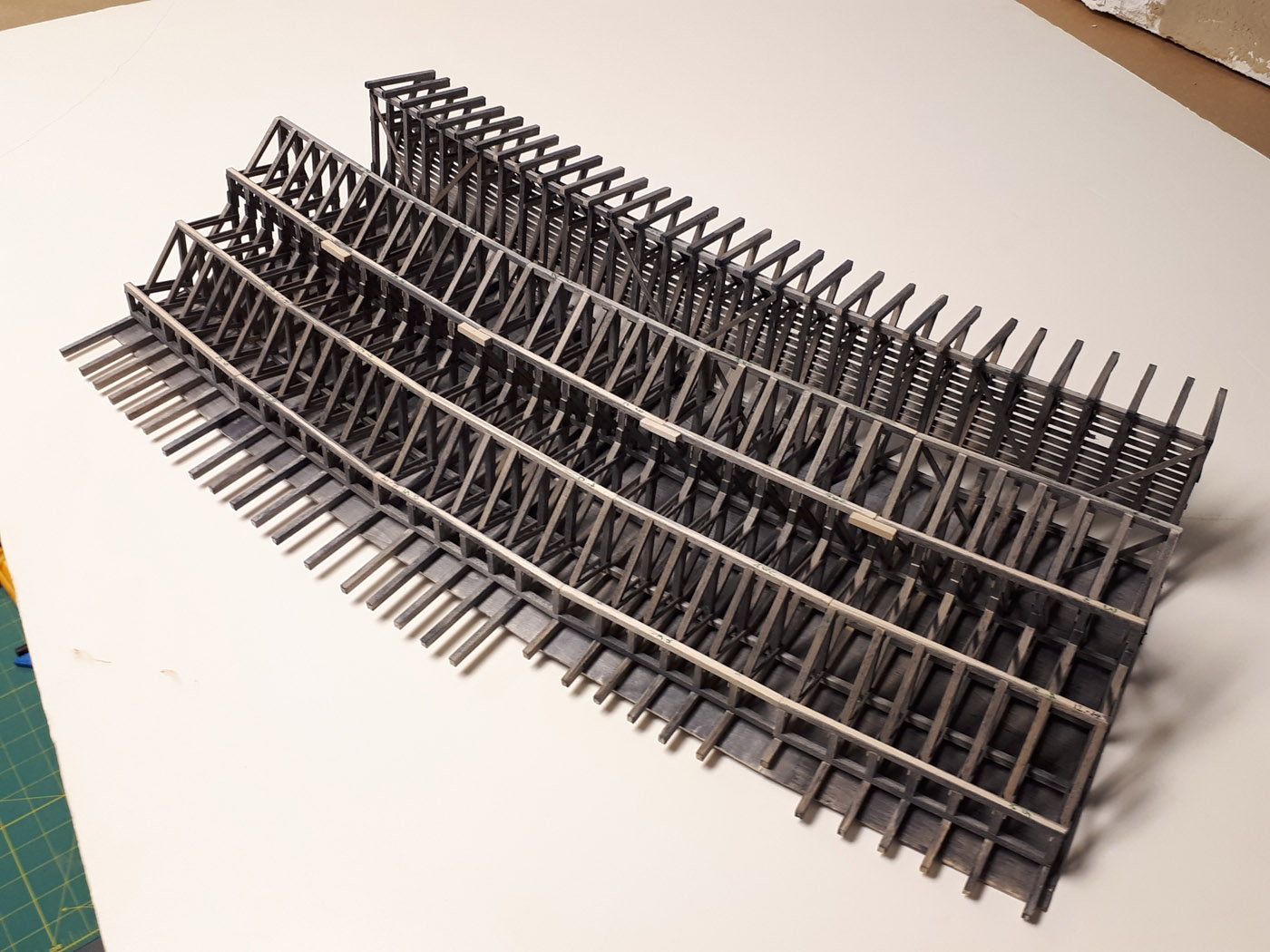
This is a very complicated structure because of the curvature in it so I developed numerous jigs, and construction aids to help get it right. I built the 5 roof panels first on the base that I had made for the shed. I next built the 2 end sections and the centre sections as separate assemblies and then infilled them with the 2 interior sections. Because I was building it upside down, it was critical that I got the angles correct since the roof is on a 1:5 pitch. I am sure I could write an article on how I built it, so will provide the following photos instead – a picture is worth a thousand words they say!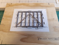

-
This was the largest model I have constructed in many years and am very pleased with the end result – given how rusty my skills were! For those that like fun statistics, the model contains over 1100 individual pieces, and has close to 16,000 scale feet of lumber in it – not including the roof deck and foundation cribbing components.
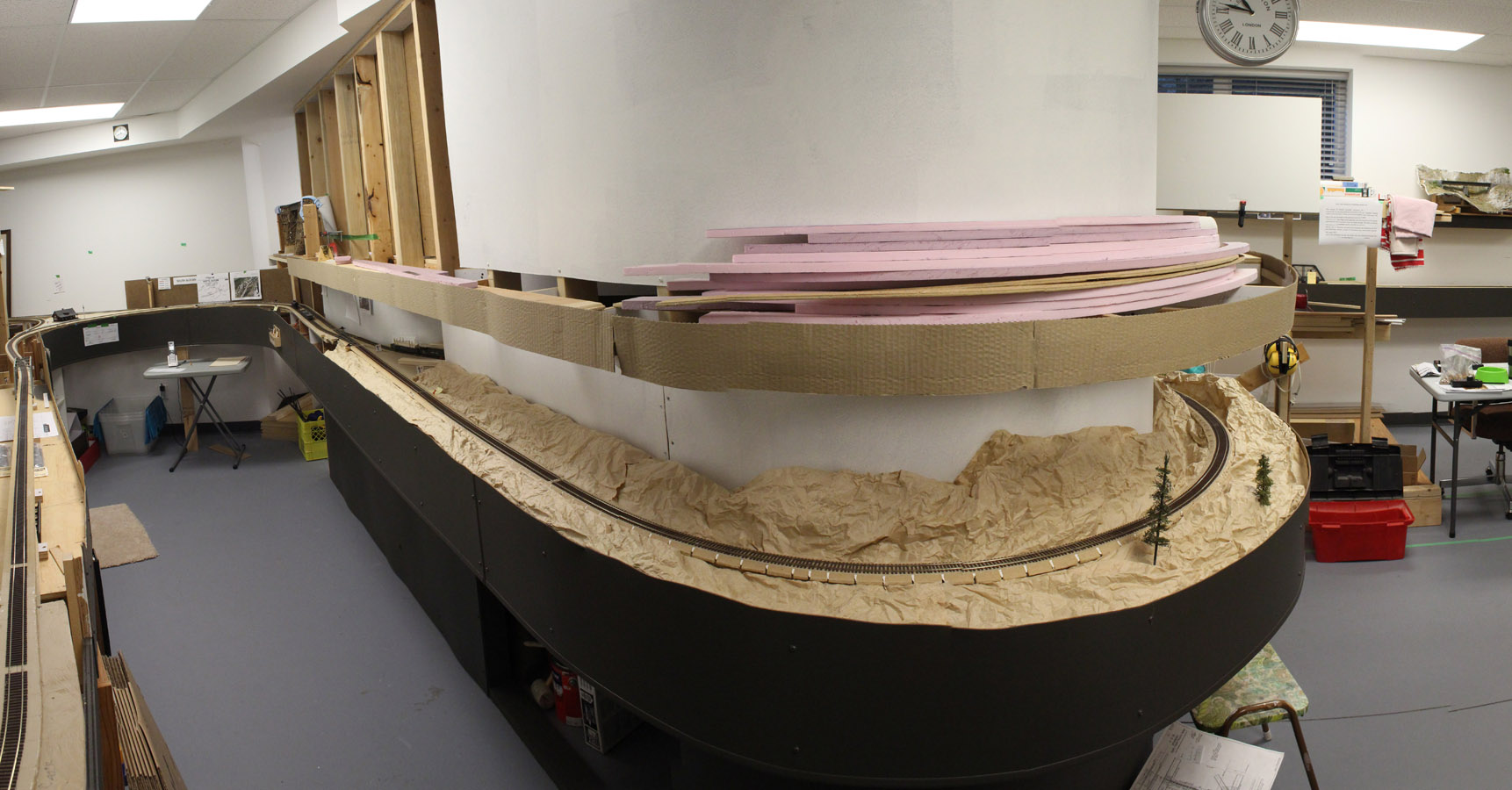
Here is a photo of the prototype, and a comparative photo of the completed shed staged in the Styrofoam scenery base. I am looking forward to integrating it into one of the signature scenes on the layout.
- Fall 2018 | CPR Boundary Sub
Scenery Along the Kootenay River Commences
Since we commenced the scenery phase of the layout, we decided the lower deck scene along the Kootenay River that is just inside the room entrance would be another worthwhile location to introduce scenery efforts. Crumpled brown paper “scenery” has occupied this location for many years as a temporary placeholder. Always amazing how long “temporary” things remain on the layout!

-
This is another scene being modelled based on a specific location along the mainline between South Slocan and Castlegar, so we assembled a series of photos to guide us along. You can several of them clipped to the upper fascia in the photos below.
-
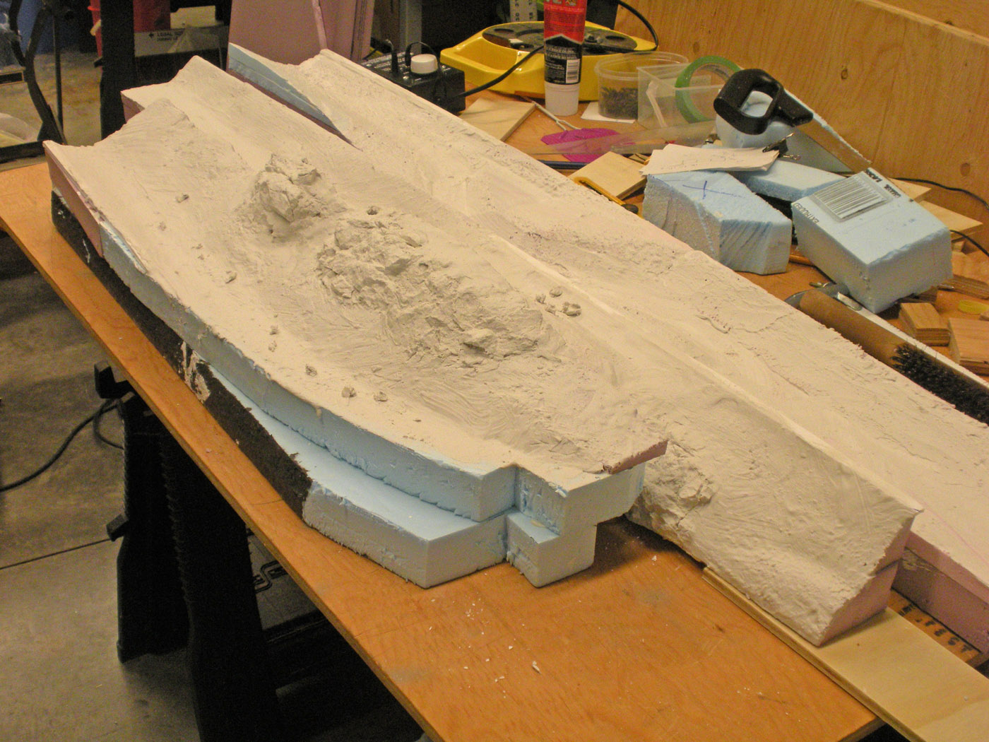
We decided to employ the traditional cardboard strip lattice overlain with plaster soaked paper towels in this area. It is fast, easy to revise if necessary and creates an immediate visual impact – even without paint! Over this we installed plaster rock castings using the wet application method. We like this method better since the mold will adapt to the topography of the hardshell easier and look more natural.

-
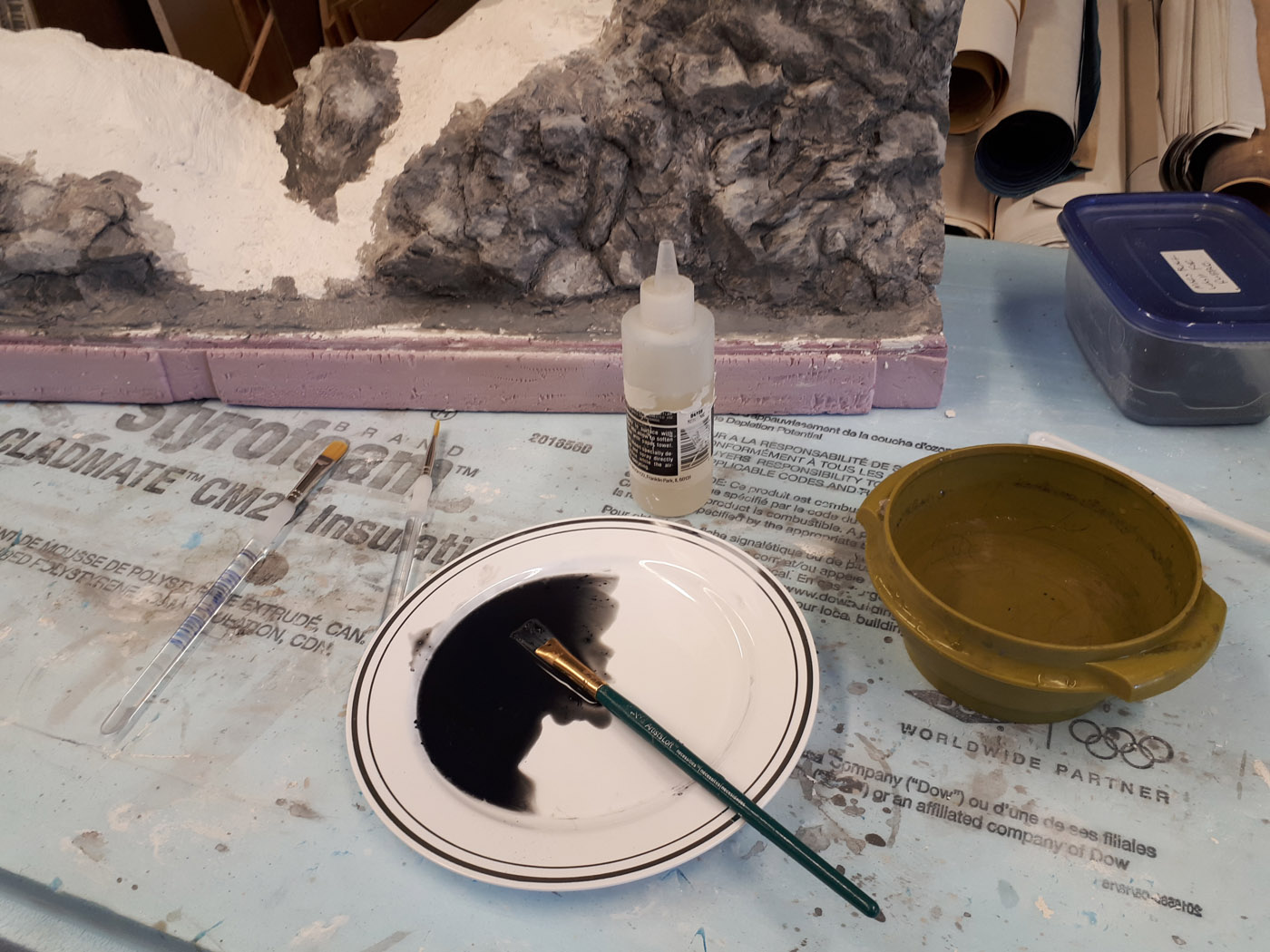
The plaster castings are painted with a diluted mix of the rock base color of latex paint over which various colors will be added to add visual variety to emulate the prototype. It then will get an application of Mars Black acrylic paint diluted and worked into the cracks and crevasses with a small brush. This is very much an iterative process and will essentially the same process as we are using on the mainline extension referred to above.
- October 2018 | CPR Boundary Sub
REsearch Road Trip
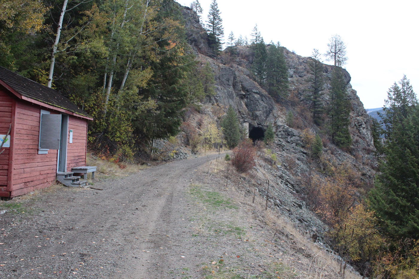
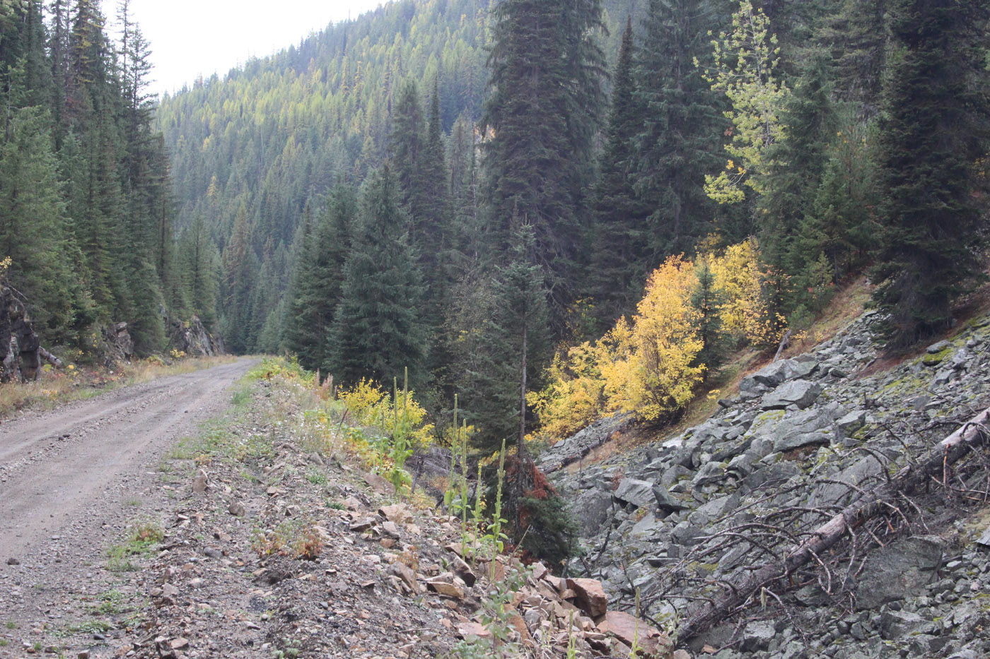
I really enjoy travelling down the Kootenay area of BC and took advantage of the opportunity to do so again this fall. Prior to the trip, I developed a list of specific tasks to do and locations to visit and photograph. This was a follow up trip to the drone photography trip I did in October 2017. See post below.
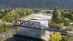
My objectives included researching the rail bed between Eholt and Grand Forks, revisiting parts of the line between Castlegar and Fife (this was one of the sections we did with the drone), photographing the major multi span bridge over the Kootenay River at Taghum (see prototype photo section) and a visit to the Touchstone Museum in Nelson. It was lot to cram into a 4-day trip; however, it was pretty successful.
Here is sampling of some the photos taken during the trip;

-
- August 2018 | CPR Boundary Sub
Furnace Filter Trees
Well, on a layout the size of, and location of the Boundary Sub, there is a need for a lot of trees – probably a ZILLION I am thinking! Even with the narrow shelf type design employed in many stretches, we are still going to need trees and then – more trees!
Most of the trees used on the previous layout were salvaged, however many more are required, so we build some when the urge or opportunity hits us. This summer we spent a few days at our cabin in the mountains with our friends; Ken & Patty and collectively built a bunch more trees while we were there. Definitely more enjoyable building them with friends, sitting on the deck looking out over the river on a beautiful summer day.


-
- July 20, 2018 | CPR Boundary Sub
Phase 3 of the Mainline
After the conclusion of the RMM meet in May, we chose to take some time off and reflect on what work would be next up for the layout. Given the size and extent of the layout, there is certainly a lot on the “to-do” list, and after studying various projects, it was decided to proceed with the construction of the next phase of the mainline extension. This will take us from the current temporary west staging yard location just east of Farron over to at least Fife, and perhaps even further.
Because this section is on the upper deck over the Nelson divisional yard, we decided it was next because its completion is required before further work can be advanced in the Nelson yard on the main deck below.
To minimize “messy” work being done over the Nelson yard, we have opted to utilize a sectional/modular approach to constructing the upper deck. The intent is to construct and substantially finish as much as possible on these sections in the garage/shop and then install them over the yard. At least that is the theory at this time.
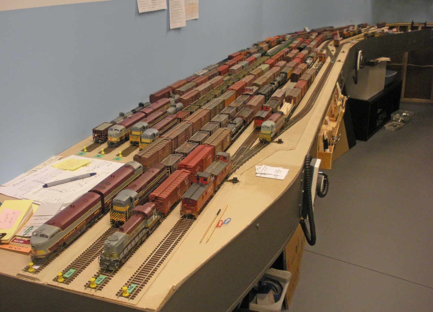
In preparation for this project, we evacuated all equipment and buildings from the Nelson yard, and moved all the locos and freight cars into the East Staging yard. See photos below;
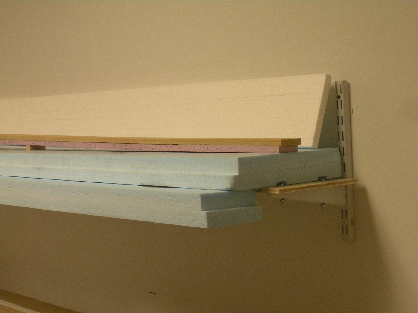
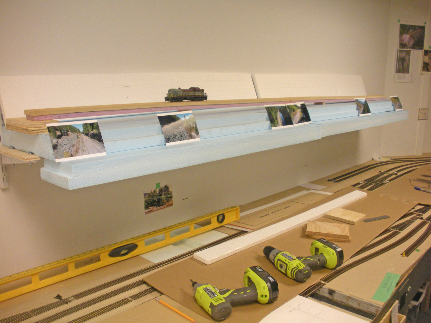
So, we initially developed a mock-up of two 48” long sections made from high density foam and supported on cantilevered metal wall brackets. They were temporarily built and installed for assessment. See the photos below. These were deemed to be too flimsy and somewhat wobbly and the concept was abandoned as a result.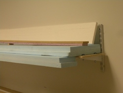
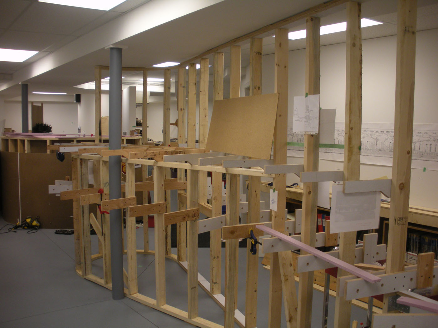
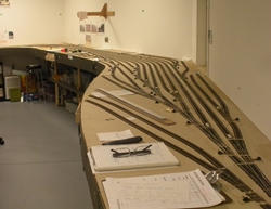
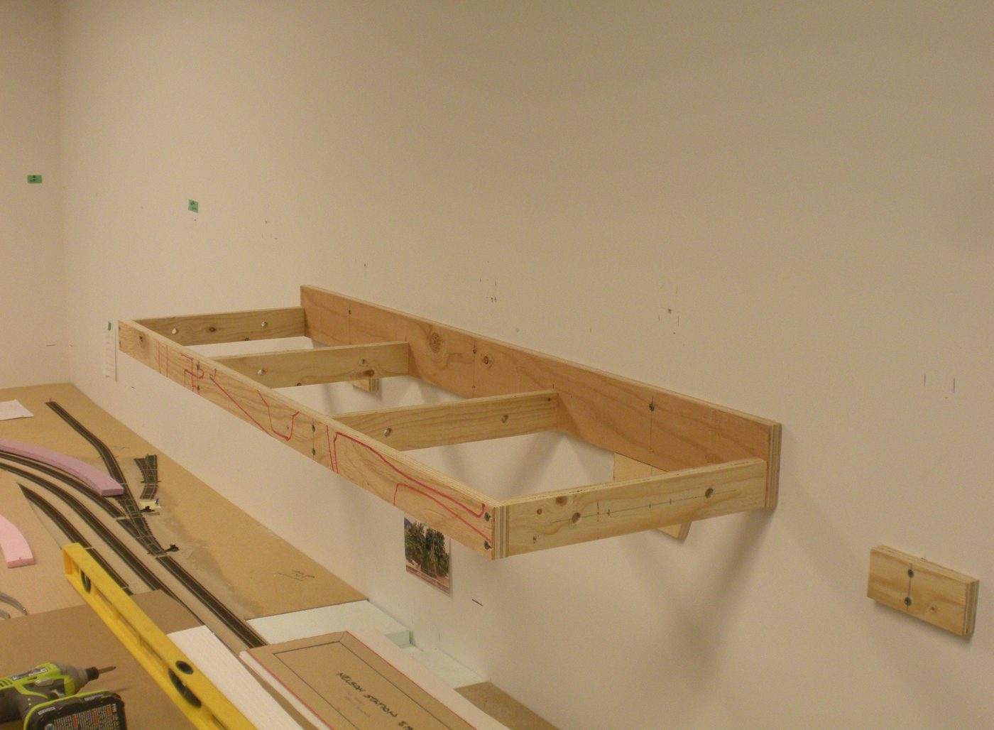
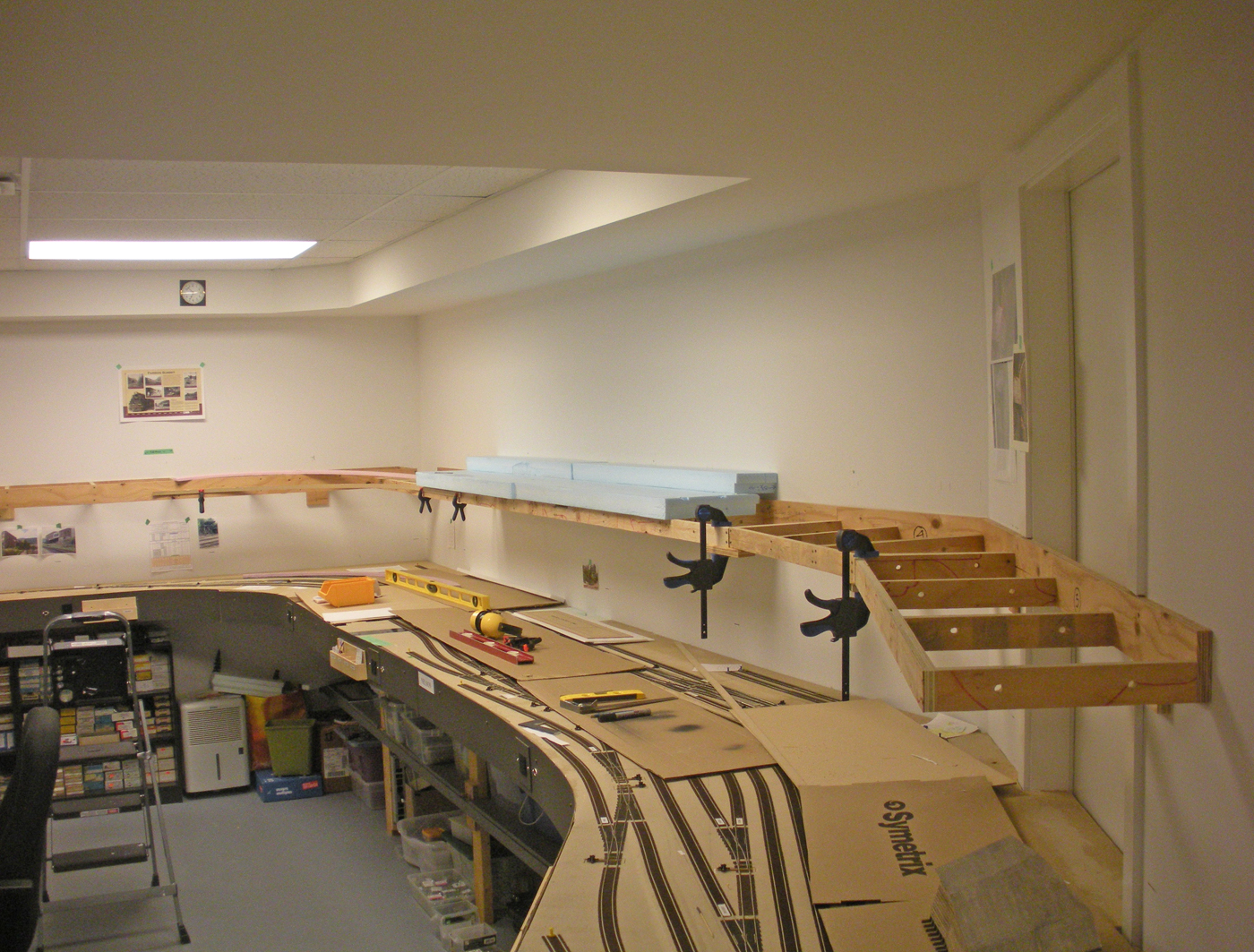
Given our satisfaction with the established strategy of using cantilevered plywood framed sections, it was decided to apply this strategy to this next phase. These sections are quite simple and will be relatively lightweight, so we opted for using ¾” plywood framing and a shallow depth of 2”. Built in 48” long sections where possible, several were done and temporarily screwed to the walls. They are pre-drilled for wiring and future lighting - as can been seen from the photos below;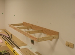
Future posts will be shared to show the progress of this phase of work.
- May 4 & 5, 2018 | CPR Boundary Sub
RMMBC 2018 Operating Session
We again this year hosted operating sessions for registrants of the annual 7th Division Railway Modellers Meet of British Columbia.
We enjoy a challenge, and tackled several projects to enlarge the layout and improve operations over prior to the sessions as are reported in various parts of this web site and were pleased with the successful implementation of those efforts. Participants from throughout the Pacific Northwest area of Canada and the USA joined us for 2 enjoyable and productive sessions.
Here are a couple photos; for more refer to the Operations Photos section.

- May 4, 2018 | CPR Boundary Sub
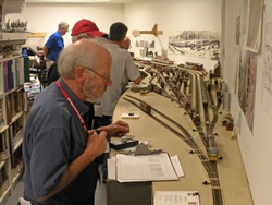
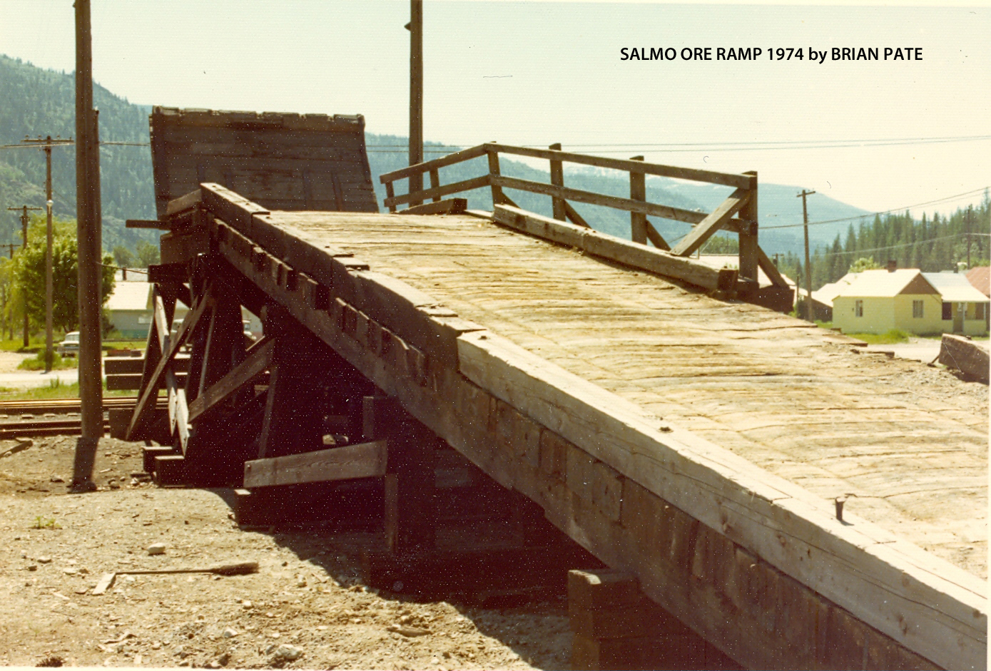
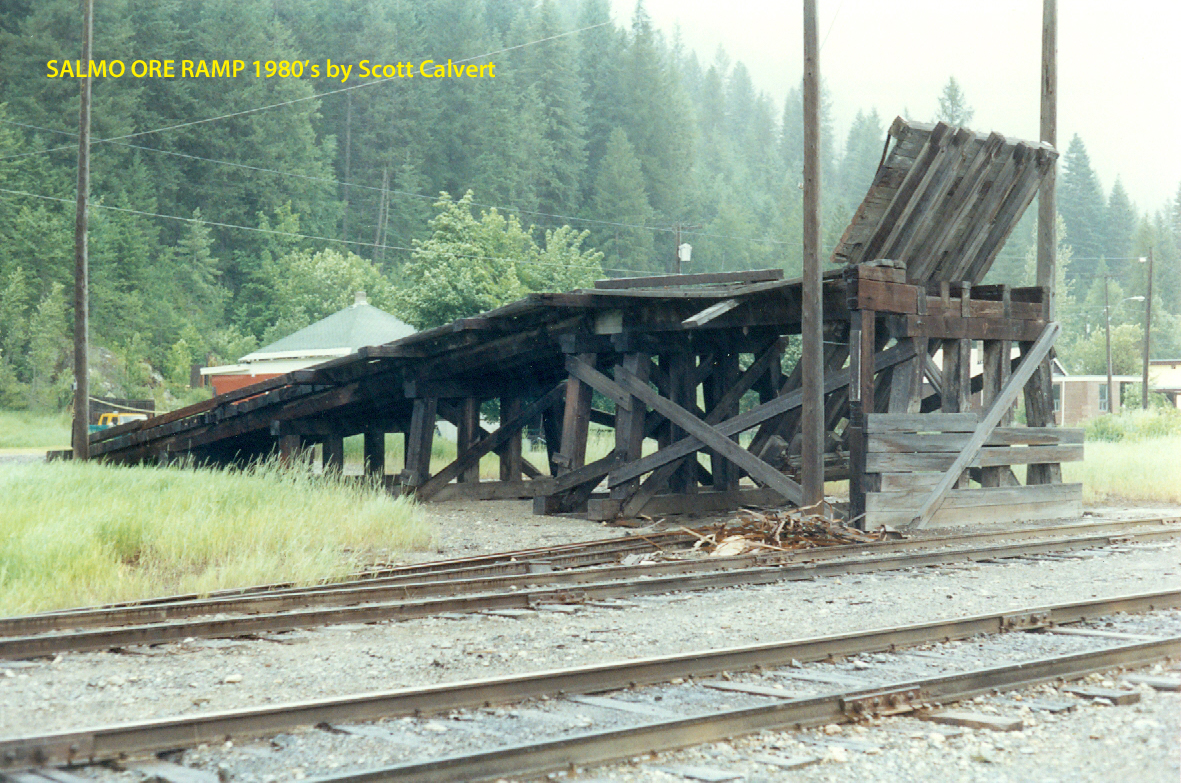
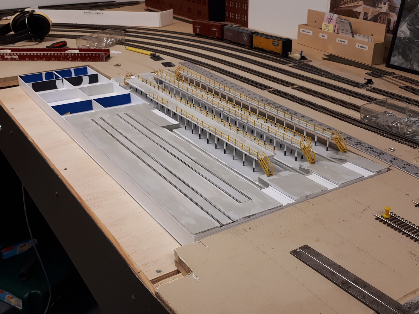
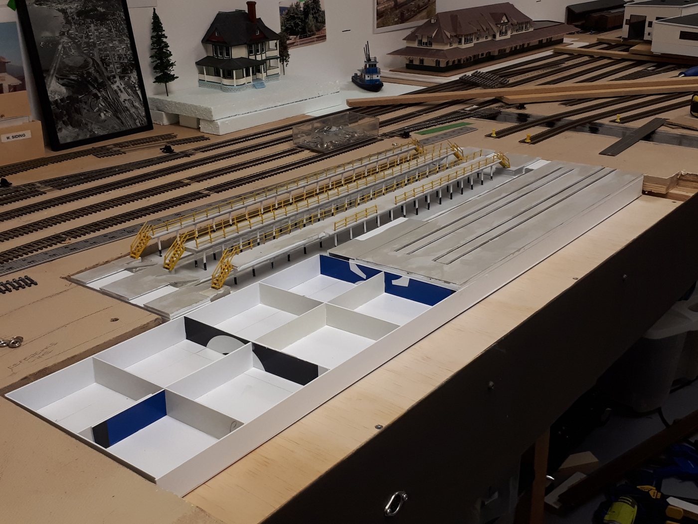
Salmo Ore Loading Platform
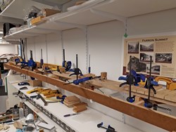
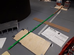
Loading and transporting ore concentrates from various locations throughout BC and Washington State took place extensively and was shipped to the Cominco operation in Trail BC. These present interesting modelling opportunities as well and realistic operations strategies. One such location was at Salmo BC on the GN 5th Subdivision line from Nelson to the USA which looked like this:
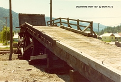
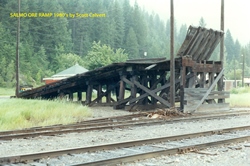
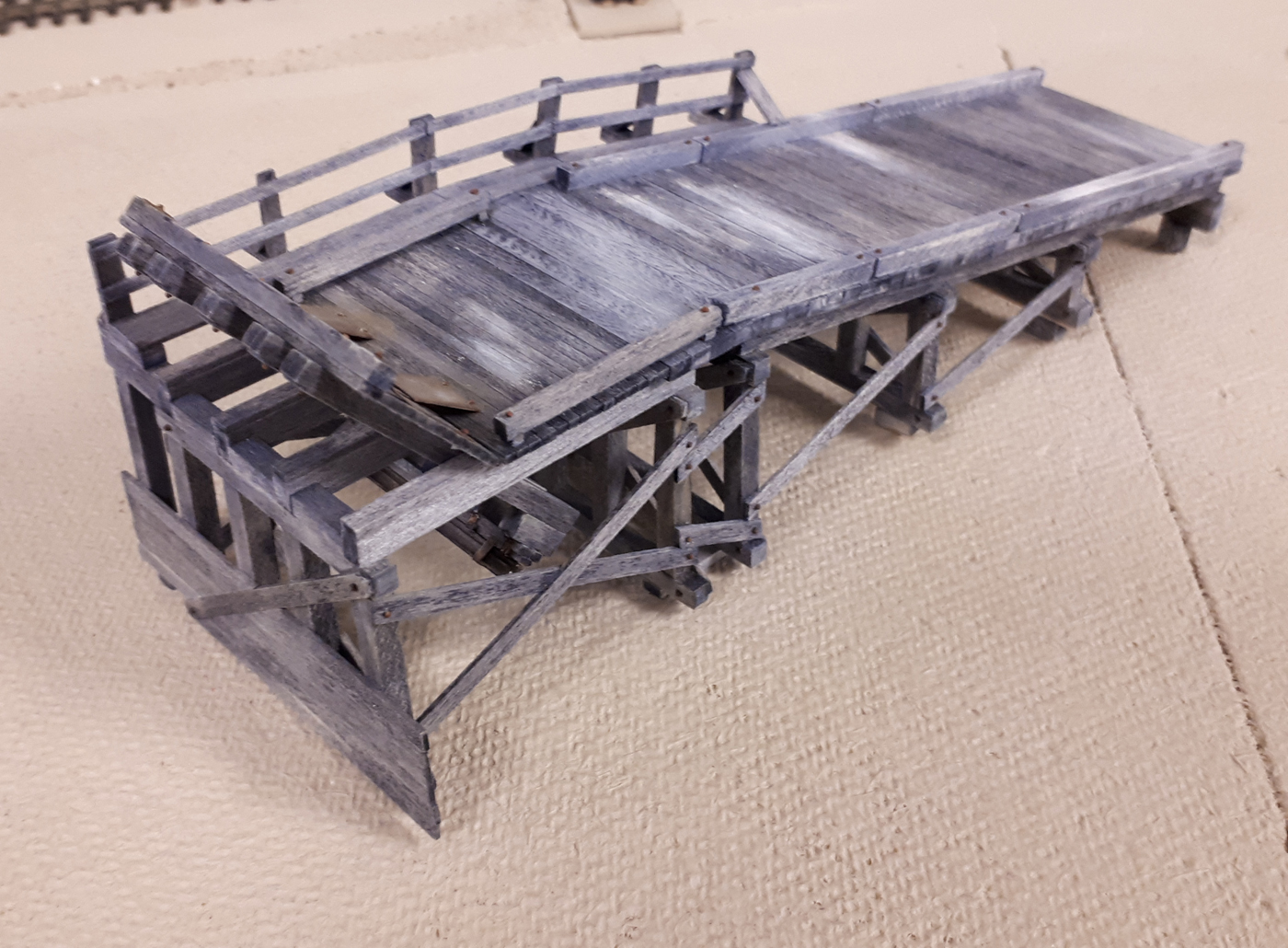
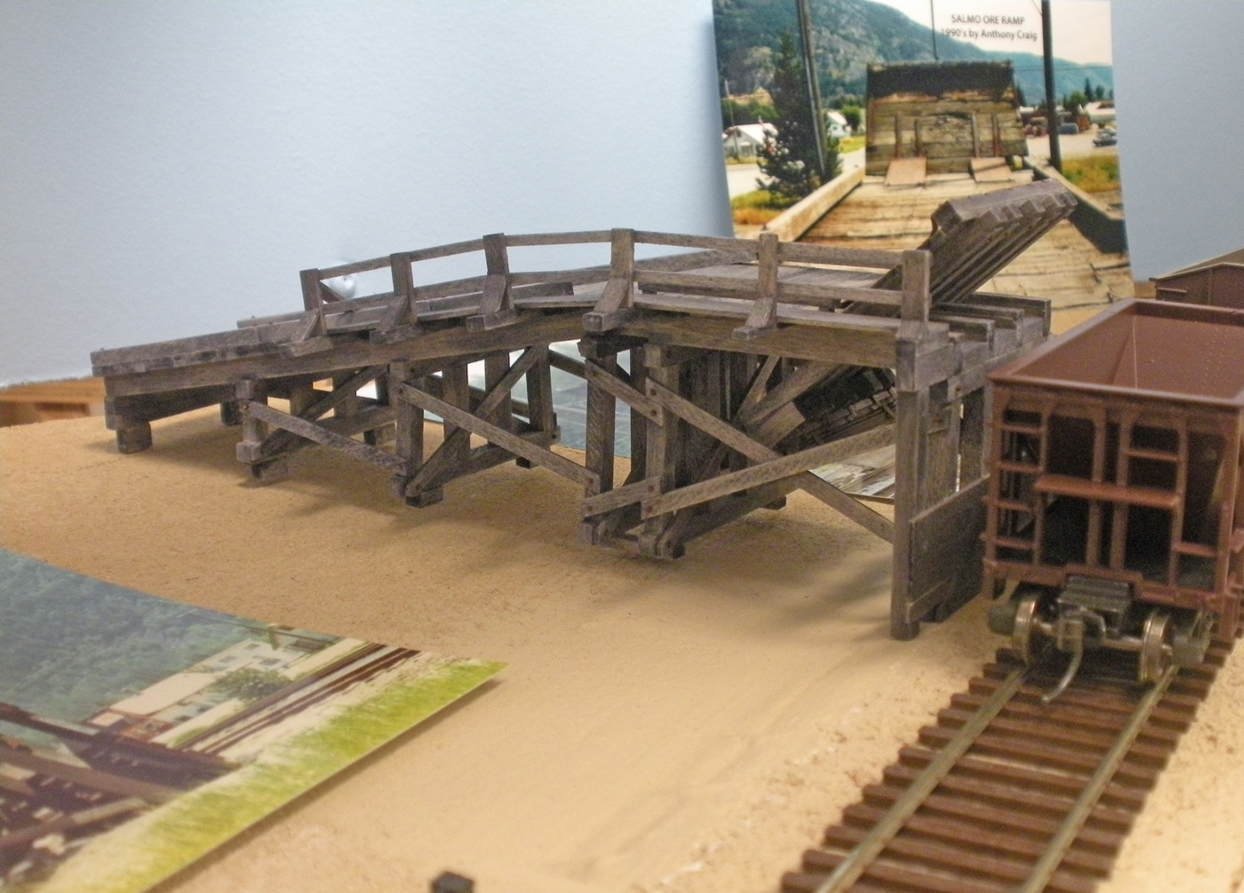
Ken Catlin graciously offered to scratch build this model for the layout. Starting with a wonderful article in the September 1996 issue of Mainline Modeller by Patrick Lawson; MMR, a detailed research program was undertaken to compile data and photos of the prototype structure. With a significant amount of info assembled,Ken redrew the plans for the platform based on the available space – this required a modest shortening of the length as reflected in the following CAD plans he prepared. In addition, he developed the use of numerous jigs to construct the model. Here is a photo of the model and associated plans, jigs, etc. at the 2018 RMMBC meet.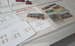
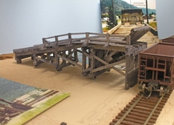
Ken invested an extensive amount of effort in constructing this model, which includes a fully functional loading ramp. This is a wonderful addition to the layout and we are very grateful for his effort. Here are a couple photos of the completed model;

- Spring 2018 | CPR Boundary Sub
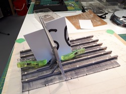
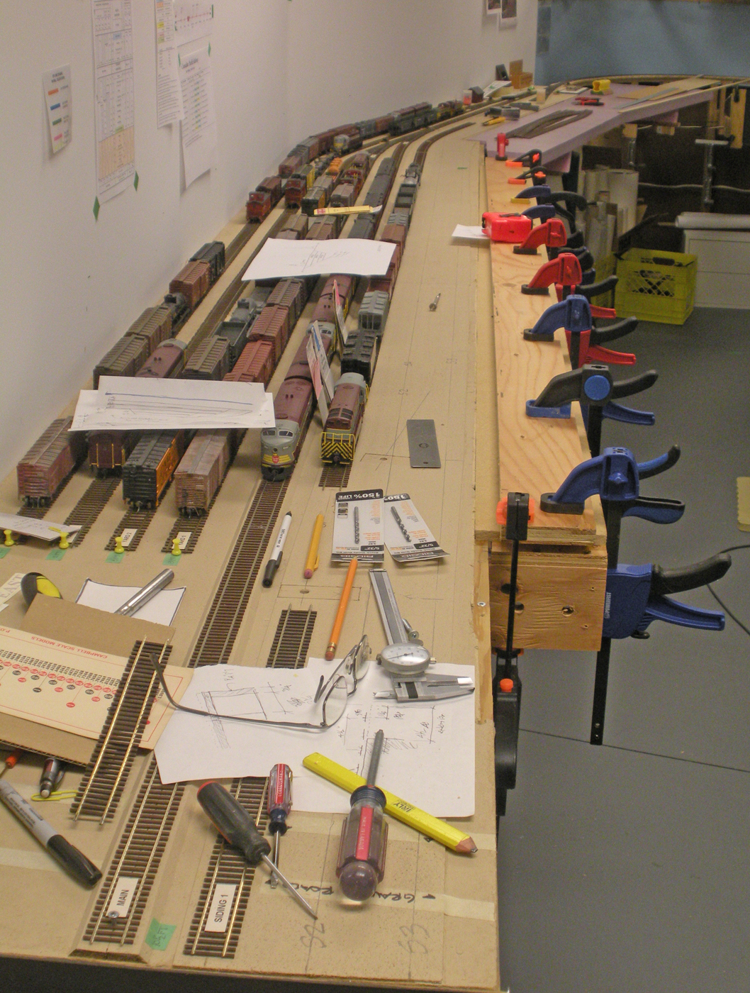
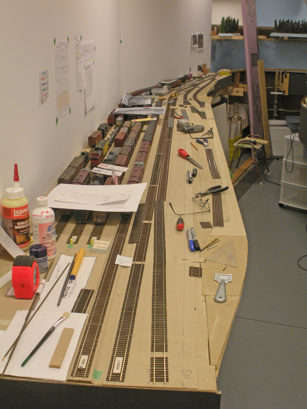
East Staging Yard Expansion & Procter Barge Slip Progress
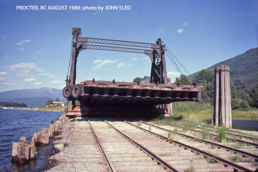
During the early part of 2018, I worked with Patrick Lawson on researching the CPR rail transfer slip and barge operation at Procter BC – east of Nelson. This barge operation was a critical link for the CPR along the Kootenay Lake until the mainline was completed along the west shore in 1930. After that, the barge operation continued serving communities along the north leg of Kootenay Lake, including Kaslo, Riondell, and Lardeau. Here is a couple photos of the prototype after it was taken out of service;
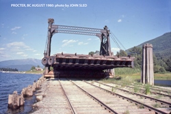
Drawings of this steel slip structure could not be located, so armed with many prototype photos – including some wonderful shots by John Sled of it out of the lake, Patrick developed some plans which we evaluated before settling on a geometry that is close to prototype, but adjusted for model railroad equipment tolerances. This transfer slip is a key component of the design of the east staging yard, therefore, we were now able to complete the installation of the remaining east staging yard tracks. Here is a couple photos of that work being accomplished;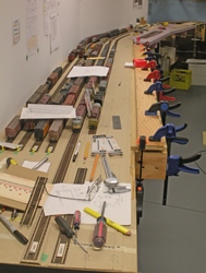


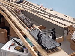
While not exact, the approach tracks to the slip are reasonably close to the prototype, although we had to exaggerate the grades and shorten their lengths to make the geometry work out. There is a lot of prep work to go before the slip can be installed, however, here is a couple photos of it placed on the layout.
-
- January 2018 | CPR Boundary Sub
BC Archives Research Trip, Royal BC Museum, Victoria BC
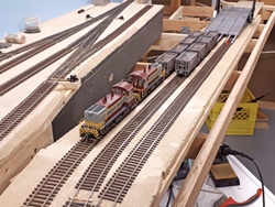
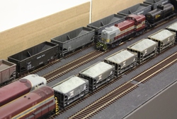
In the April 2017 post, we provided an update on the construction of the Rossland Subdivision staging yard. With that increased capacity, it became obvious that research on the traffic that was common on this subdivision was required. The huge Cominco plant at Trail BC and other associated mining customers were the main drivers of this traffic.
So, with this in mind, I embarked on a research trip to the BC Archives at the Royal BC Museum located in Victoria, BC. With the help and guidance of renowned author; Robert Turner, I successfully enrolled as a Registered Researcher and spent 2 days at the archives researching the Trail operations. The staff there was extremely helpful (and patient!) and I came away with a significant amount of info and photos. Like many archives, a lot of documents are not digitized; however, they had some useful written lists that greatly helped in locating things.
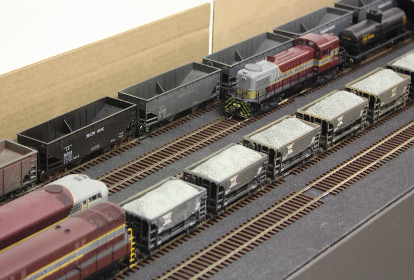
Bill Dixon assumed the challenge of distilling the data and information I obtained and with his help, and based on the prototype CPR Employee Timetables, an operations scheme was developed for trains to and from this Subdivision. This then allowed us to supplement the loco and freight car fleet in an appropriate manner – in fact, he has loaned over 75 cars to the layout in response to the increased traffic demand! Here is a photo of the added ore car fleet and some of the loads Bill made for them.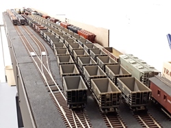
The process is not completed yet, and as with any project like this; More research is required!
- October 1 to 4, 2017 | CPR Boundary Sub
drone research trip
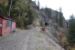
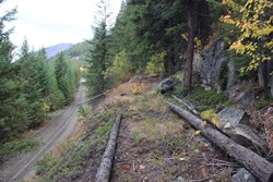
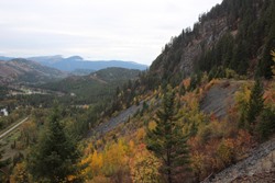
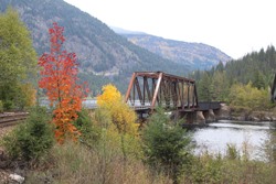
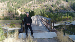
My nephew and I spent several days on the abandoned rail line -now part of the Trans Canada Trail (TCT) taking drone and still photos from the end of the operational CPR line just west of Castlegar to Cascade near the US border. This was an amazing experience and resulted in a substantial amount of footage. We are not aware of anyone using this unique approach to “railfan” a railroad line.
I must point out that this work was done with the express permission of the Columbian and Western Trail Society who maintain this section of the line under agreement with the Provincial Government. We had to file papers for approval and my nephew is a trained professional drone operator. Drones can be extremely dangerous and must be operated under the strictest controls by skilled operators. Some of our work will be posted on the trail societies’ web pages in the coming months for educational and promotional purposes.
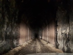
A drone’s vantage point can easily be set to emulate the viewing angle that a modeller has when viewing a layout, so we ended up with a lot of material that will assist us when constructing this section of the layout. All major tunnels and bridges remain in service as part of the TCT, several of which are included on the layout, so this was a wonderful opportunity to film them for posterity.
There is a huge amount of footage to still process, however, we offer the following as example still shots of what we captured. The videos still need to be edited and then will be posted and provided to the Trail Societies. Watch for updates on this in 2018.


- September 8 to 10, 2017 | CPR Boundary Sub
vanrail 2017 op sessions
As part of this biennial invitational operations event, the Boundary Sub again hosted 3 back to back sessions over the 3 days as well as the Friday evening social which was attended by close to 80 people. This was the second VanRail event for the new layout and we were very pleased with how it performed. This would not have happened without a lot of help from my home road crew!
This year’s event had a record number of guests, and layouts, and we were very pleased with the participation and interest in the event.
Here are a few photos taken during the sessions, for more refer to the Operations Photos section:
- August 22, 2017 | CPR Boundary Sub
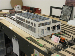
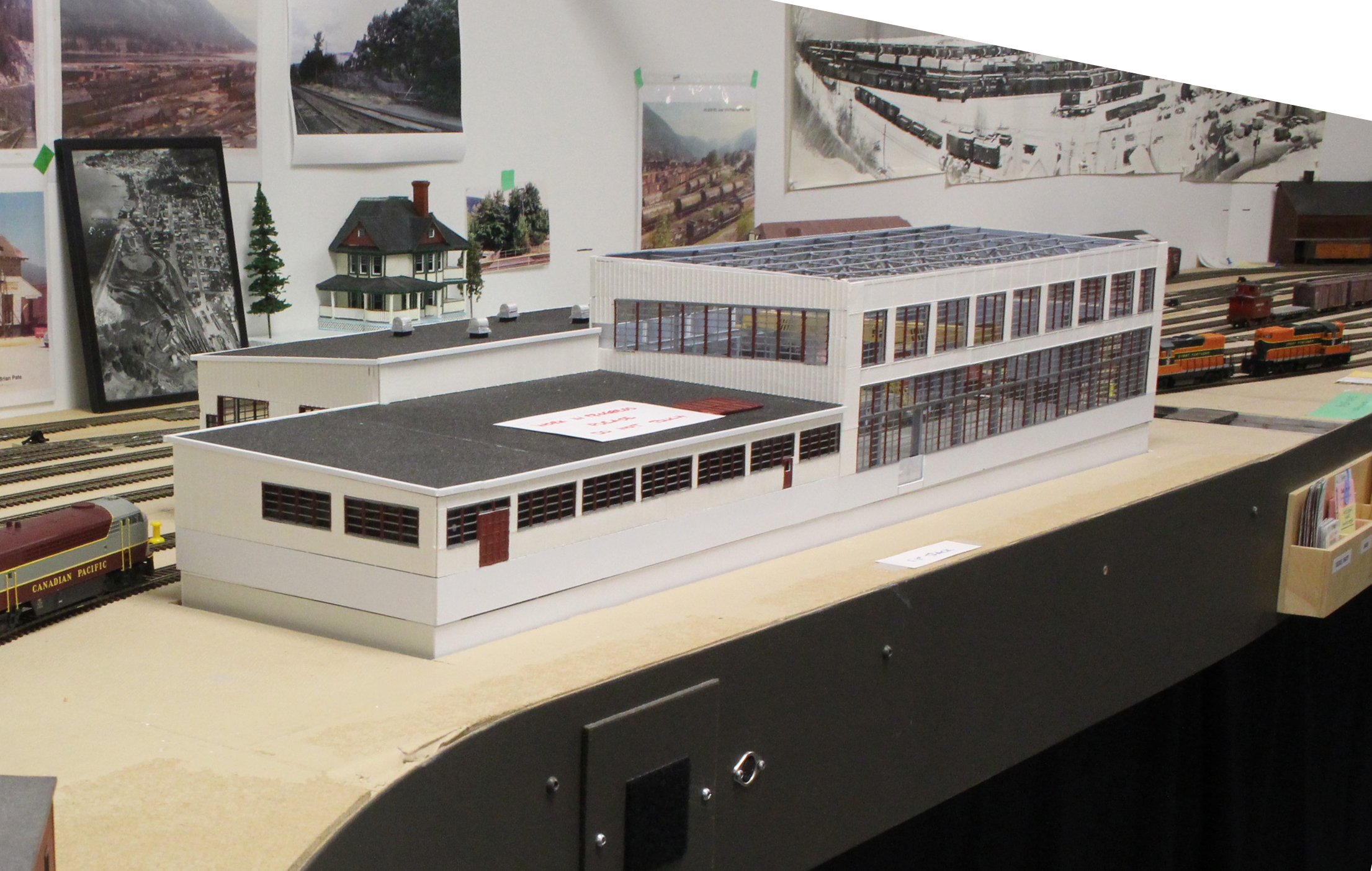
nelson diesel shop arrives!
This iconic structure was an essential building to include in the Nelson divisional yard, and I was thrilled that Patrick Lawson, MMR offered to construct it for the layout. His plans and article on this facility were published in the December 1996 issue of Mainline Modeller which gave us a solid starting point for planning the building.
While the yard has sufficient space to accommodate all 4 tracks, the building length needed to be reduced somewhat due to space constraints at the east end of the structure. After experimenting with various combinations, we settled on a design that was 80% full length while still retaining the overall character. Most people familiar with the prototype would not notice the reduced length.
Because the prototype had a huge number of large windows, especially on the side facing the main aisle, we concluded that the interior where tracks 3 & 4 are located needed to be detailed since it was so easy to see. Patrick developed a technique of constructing a Plexiglas shell for the entire superstructure onto which he laminated 3D printed window/wall panels. He also 3D printed all the roof trusses, overhead crane gantry, mechanical ventilators, handrails, and numerous other parts.
Tracks 1 & 2 were the run through tracks where locomotives received only light servicing and are less visible on the model so that area of the building will not be detailed except close to the large overhead doors. However, the tracks in this area ran on elevated steel framing which created a pit under the entire area – so, the model base had to accommodate that depth. As a result, the base was constructed separately and is designed to be recessed into the layout by 1.25”. This also allows the superstructure to be removed for access to the building interior should we need it. Here are a couple of photos with the base placed on top of the new dropped plywood subbase:
While not fully completed yet, this building is still a commanding structure on the layout. It is now my job to complete the layout framing modifications. And then paint, weather and complete the final detailing as well as interior and exterior lighting for it. Watch for future posts showing the final installation and completion of the trackwork. Meanwhile here are a couple of photos of the overall building


- August, 2017 | CPR Boundary Sub
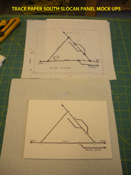
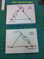
south slocan turnout controls
This particular location has always presented a challenge to operators because of the wye configuration and the distance to some of the turnouts from the main aisle. I wanted to address this before the upcoming VanRail event, so we tackled in a similar manner to the previous work done in Castlegar. See the entry below titled; Spring 2017 | CPR Boundary Sub Turnout control installation.
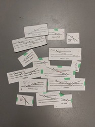
Tortoise machines were installed for all the turnouts and controlled by “drivers” and two temporary control panels were constructed. The control panel geometry was a bit tricky, so I did up some trace paper mock ups to allow us to visualize how they would work out. The temporary panels will eventually be replaced with better quality ones that will probably be recessed into the fascia.

- August, 2017 | CPR Boundary Sub
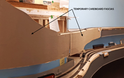
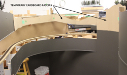
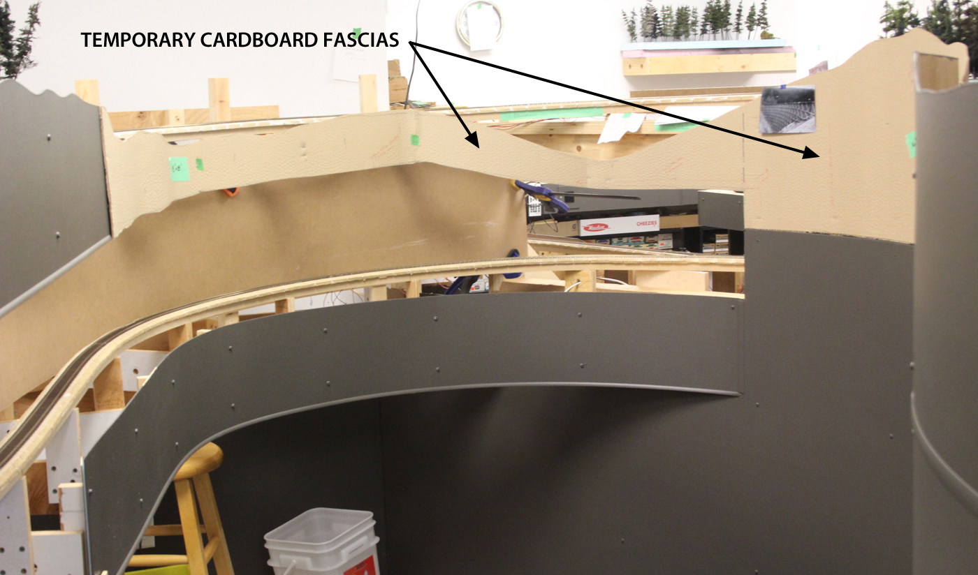
more fascias & backdrops!
In preparation for the VanRail 2017 event, we decided to install and paint some more fascias and backdrops. Adding them is relatively easy and really has a significant visual effect on the layout. I was fortunate to have the assistance of Ken Catlin and John Martin to complete this work.

-


-
There are a few sections where the geometry is a challenge, so we elected to mock some fascias up using corrugated cardboard. It is cheap and we can trim it or even replace it if it doesn’t seem correct. -


- July, 2017 | CPR Boundary Sub
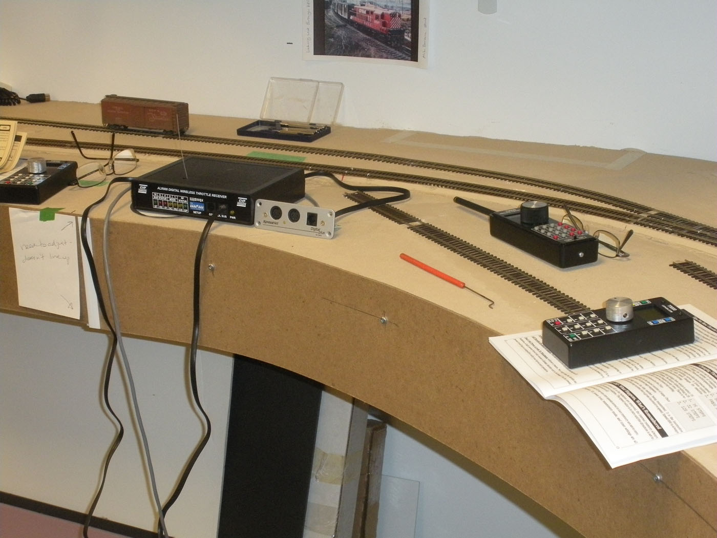
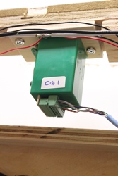
electronics system upgrades
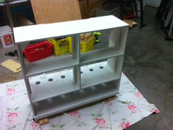
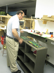
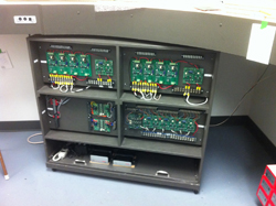
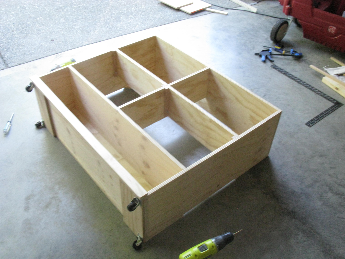
I am the first to admit I am NOT a tech guy, so when it came time to replace the electronics cabinet with a larger one capable of housing all the equipment necessary to support the ultimate layout, I reached out to several members of my home crew to assist me.
-
The layout had reached the point where the existing DCC system and breakers were being taxed, and we thought we had better rectify that before it decided to quit – which, as we all know – would happen during an op session! -
So after assessing how many boosters, power supplies, breakers and reversers would be needed for the eventual complete layout, we then added more to be safe. Then we dismantled the old cabinet and stripped out all the electronic stuff. Based on the new requirements, I designed and, with the help of Ken Catlin, built a custom new cabinet to house everything. The new cabinet was put on casters to make it easier to access the rear where a lot of the bus wiring comes in. we also have a small fan to cool the command station, boosters and power supplies - a couple of local guys have experienced some overload to their DCC systems due to heat. -
Although there is space for everything, we only installed part of the equipment at this time – partly due to budget constraints!
-
- July, 2017 | CPR Boundary Sub
110 Volt wiring additions
When we built our home several years ago, I had the contractor rough in some additional circuits out of the layout room sub panel for future use. Now that the majority of the layout main deck and associated pony wall framing is completed, it became time to extend those circuits into the walls and ceiling areas.
-
In total, we added 12 duplex outlets around the layout support walls, 3 junction boxes in the main layout peninsulas to feed the planned under deck lighting, and several more junction boxes located conveniently in the ceiling. -
The room was quite a mess during this work as can be seen from these couple photos, however, we had it all back together before we resumed operations in August. -


- May 5 - 6, 2017 | CPR Boundary Sub
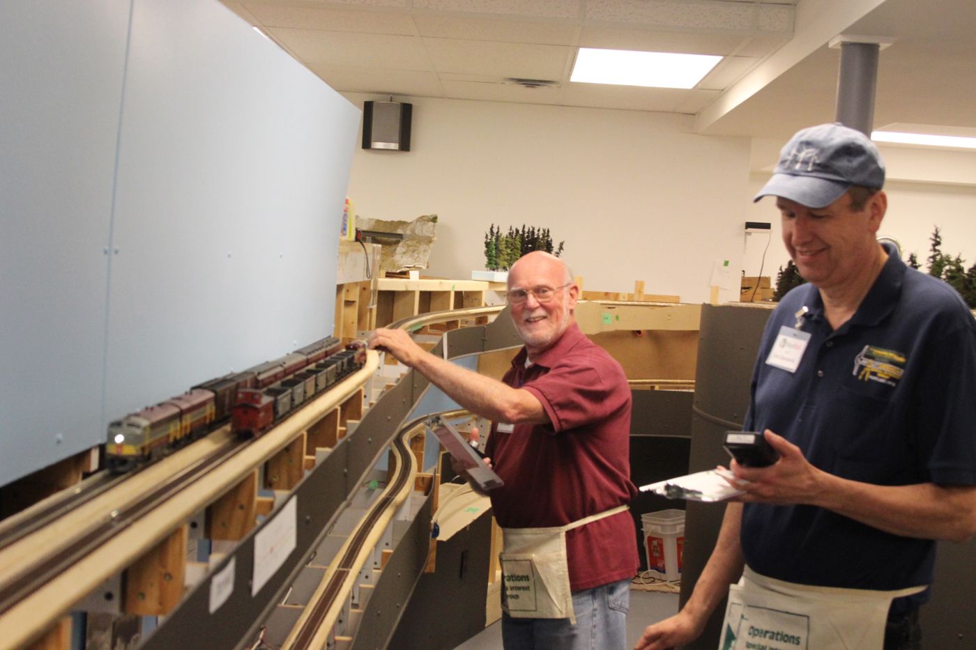
RMM 2017 Op sessions
 Operations is a fundamental objective for the layout, and we are therefore, always pleased to host operating sessions for registrants of the annual 7th Division Railway Modellers Meet. The dates for this event were recently revised from November to May, and as a result, the Boundary Sub and several other local layouts hosted sessions with only 6 months between the 2016 and 2017 events.
We enjoy a challenge, and tackled several projects to enlarge the layout and improve operations over that 6 month period and were pleased with the successful implementation of those efforts. Participants from throughout the Pacific Northwest area of Canada and the USA joined us for 2 enjoyable and productive sessions.
Here are a few photos; for more refer to the Operations Photos section.

- April, 2017 | CPR Boundary Sub
Newest crew member
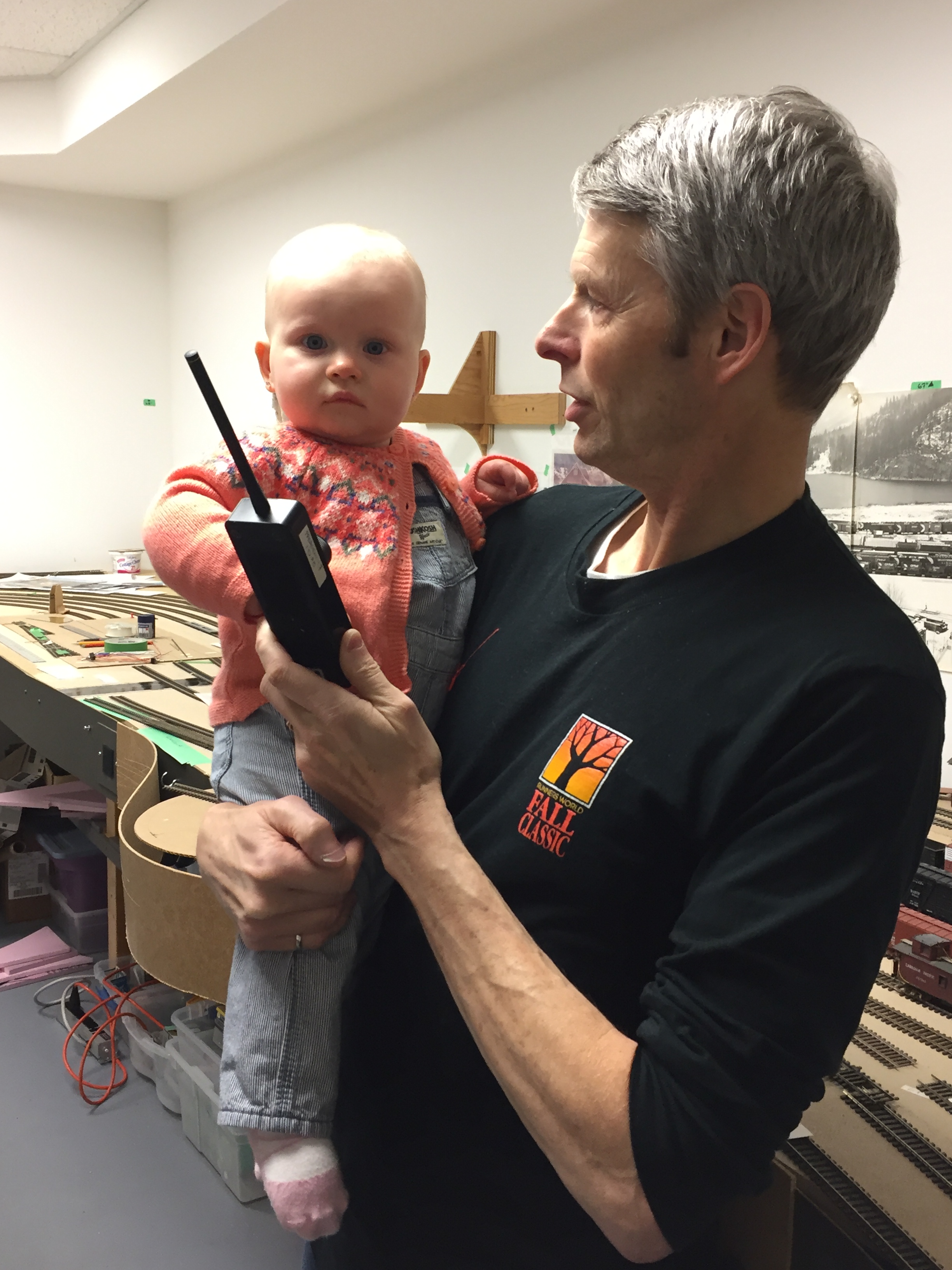
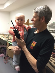 Wren Emilia Calvert, born in Australia on April 14, 2016 and recently moved to Canada, has joined the Boundary Sub project team as the youngest member. While she cannot reach any of the actual layout, and has only recently started to walk, she is providing valuable advice and input related to the need to increase capital investment in equipment to keep pace with the physical expansion program. We also anticipate she will be providing critical IT support services – once she learns how to talk!
- April, 2017 | CPR Boundary Sub
CPR Rossland Subdivision staging yard
 Early this month, this important staging yard was placed into service on the layout. Originally conceived to be located in a storage closet in my wife’s adjacent quilt studio, and affectionately referred to as “Quilt City”, a redesign and some modifications of track alignments in a couple of places yielded a more practical location in the separate part of the layout room where the Dispatcher is located.
This yard was constructed using the typical plywood “module” approach we have used for other areas of the layout which would allow it to be slid out of its position in the future should we need to do so. In addition, all the pre-wiring of bus and feeder wires was completed while the module was on its side before it was installed.
Connected to the mainline at Castlegar, the prototype Rossland Subdivision provides service to the large Cominco plant at Trail, BC. At 6 tracks, this yard is designed to handle a representative flow of traffic to and from this customer as well as ancillary industries in the area. We are slowly increasing the freight car fleet and introducing appropriate trains into our ops scheme to reflect this addition to the layout. Ongoing research is underway in studying the types of cars and loads that are to be modelled.
Here are a few photos; for more refer to the Layout Photos section.
- Spring 2017 | CPR Boundary Sub
Turnout control installation
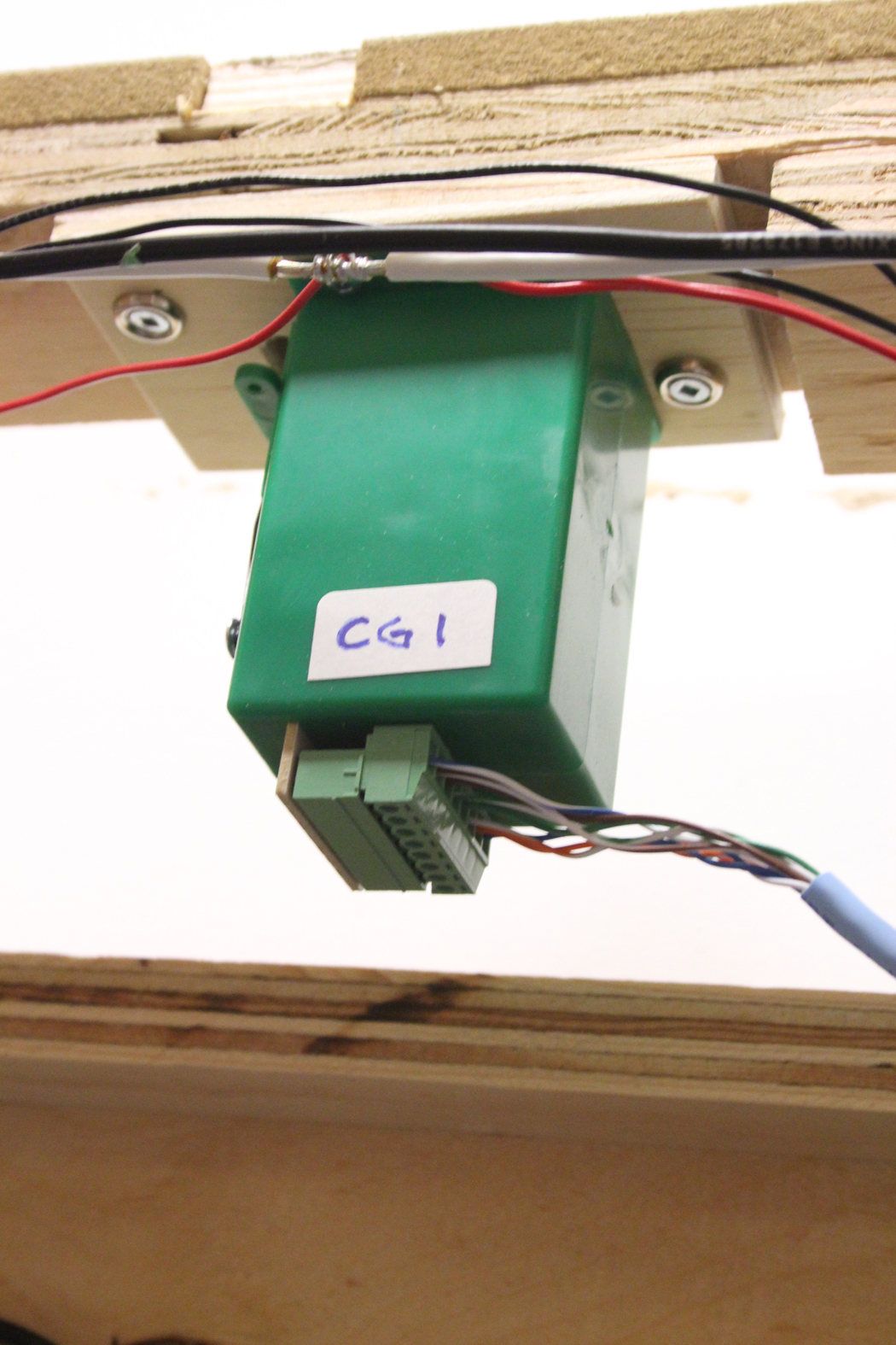
As part of the revision and upgrades to both Castlegar and South Slocan, it became necessary to install turnout control switch machines in numerous locations. These would be the first to be installed on this version of the Boundary Sub, but not the last by far. Tortoise slow motion machines were selected primarily because I have a large number of them in stock. We are also quite interested in the much smaller and more affordable MP1 & MP5 ones distributed by Model RailRoad Control Systems; http://www.modelrailroadcontrolsystems.com/ and recently purchased several to experiment with.
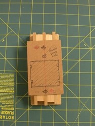
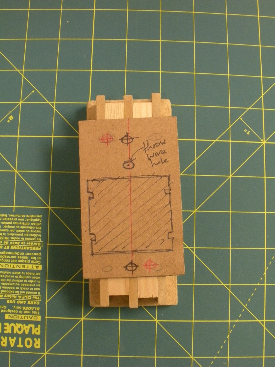
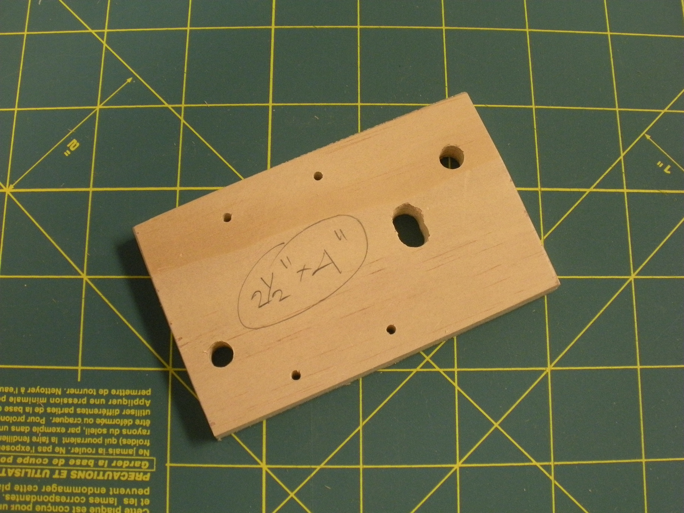
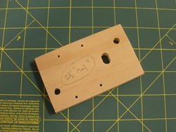 Adopting the philosophy that if things are constructed to be easily removed for maintenance, it will probably never have to be done, we set about developing a universal mounting bracket with some placement tolerance, and we also wanted a wiring connection that was also easy to disconnect.
In my opinion, the Tortoise machines provide virtually no tolerance for installation to the underside of the layout. We wanted to have tolerance in both the lateral and longitudinal directions to make the installation work easier. Also, because spline roadbed is used for a lot of the layout – which is quite narrow – we needed to develop a mounting strategy to account for the fact that the Tortoise is wider than the spine system. As always, I reached out through the net and asked folks for their thoughts and opinions, and was very pleased with the feedback I received. I have to admit that some of the installation techniques were very unique and I felt that some may be problematic over time. On a large layout like the Boundary Sub, we work hard to make things as reliable and bullet proof as possible.
I also found a really neat 3D printed mounting bracket online and ordered a couple for research purposes. Here is the link if you are interested; https://www.thingiverse.com/order:8581 While pretty slick, they only offered tolerance in one direction and are quite costly by the time the currency exchange and shipping costs are factored in. So, we proceeded to develop our own by trying out several cardboard mock ups for possible configurations. The final mounting plates are made from 3/8” cabinet grade plywood – actually scraps from the roadbed for the helix – see the February 8. 2016 entry below. See some photos below.
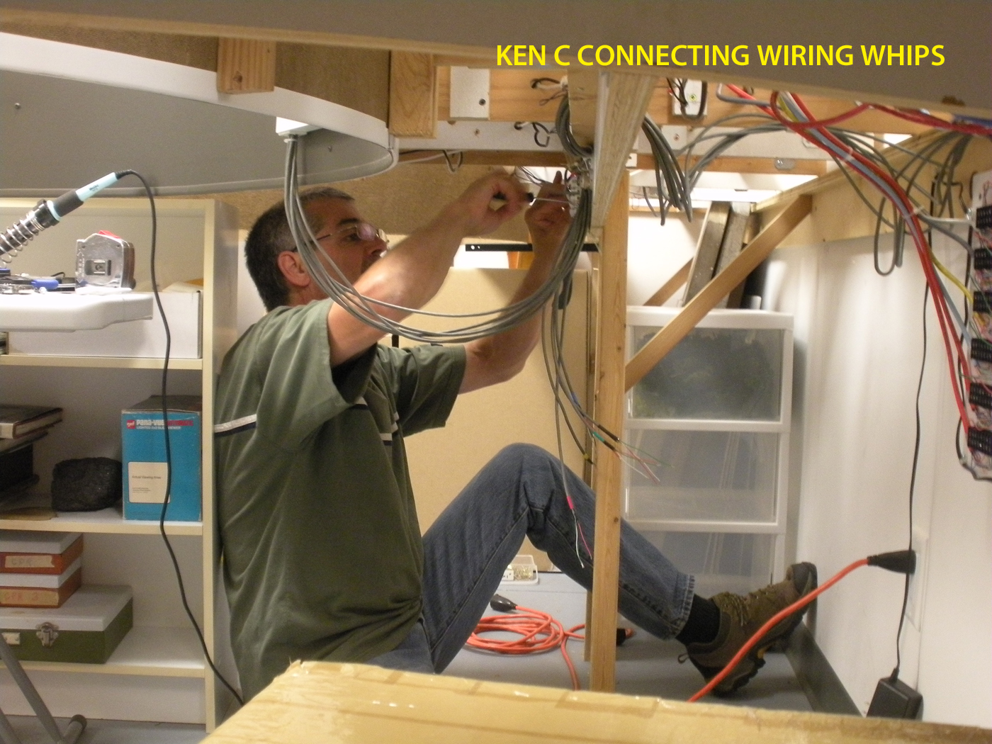
We also wanted a wiring harness that could be easily removed should the machines fail or in case modifications were required. So, with the help of Doug Hicks, we soldered female plug assemblies on to the machines, and a wiring whip on the male end of the plug as can be seen in the photos.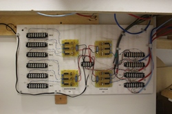
- January / February 2017 | CPR Boundary Sub
Castlegar Yard Improvements
In anticipation of the introduction of a staging yard which would represent the Rossland Subdivision in the near future and in recognition of the congestion and confusion that takes place in Castlegar during op sessions, we undertook numerous revisions to the yard area.
Up until now, the wye was incomplete and the yard tracks were somewhat awkward and inefficient, and these needed to change. There was also an opportunity to add more local switching locations.
So, the dead end portion of the yard tracks were removed so accommodate a reconfiguration that would allow them to become double ended. This required modifications of several Shinohara curved turnouts and the installation of a reverser circuit breaker by DCC Specialties.
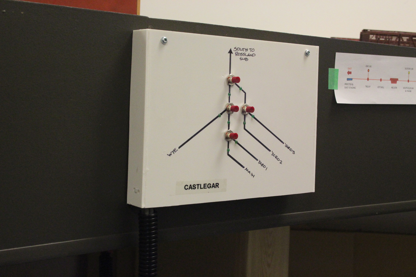
The reconfigured yard tracks and newly completed wye would connect to, and feed the Rossland Subdivision staging area. The new turnouts were beyond reach and required the installation of slow motion switch machines and an associated control panel. Because of the desire to have consistent switch machine controls on the layout regardless of where they are, we chose to operate the machines by a push button and not a toggle switch. After some research, we settled upon using circuit board “drivers” manufactured by Ron Paisley; http://home.cogeco.ca/~rpaisley4/3556StallAltern.html
We will address the actual switch machine installation and operation process in the next posting.
Here are a few photos showing the revisions to the Castlegar area.


-
- November 3 - 4, 2016 | CPR Boundary Sub
RMMBC Op sessions
One of the highlights of the annual modellers meet here in Vancouver, is the operating sessions which I have coordinated for many years. The Boundary Sub (both current and previous versions) has been one of the layouts included in the offering and we really enjoy hosting guest sessions. As most operating layout owners know, a great deal can be learned from guests that are new to your layout and operations scheme. Their perspective can be quite illuminating.
-
This was the first opportunity for new folks to operate the layout with the 130 foot mainline expansion that was completed earlier this summer. In fact, we only hosted three home crew sessions on the expanded layout before welcoming the RMMBC guests. A little blind faith never hurts in these circumstances!
Each session had 8 guests participate and their Ops skills ranged from “newbie” to “experienced”. Regular crew member; Rene Gourley kindly dispatched both sessions with his usual skill, and Ken Catlin provided veteran home crew support for the visitors, and as a result things went very well under their guidance.
Here are a few photos of the session.


- October 12, 2016 | CPR Boundary Sub
nelson Superintendents house
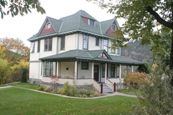 In 1911 the CPR constructed a beautiful residence for the Superintendent of the Kootenay Division on an embankment just above and to the immediate east of the Nelson station building. The residence has had several occupants – railroad and otherwise, over its lifetime and is considered a heritage structure and has been preserved with few revisions. This house typifies many of the premier homes that were constructed for railroad executives all across Canada. A recent photo is included here.
 -
The initial plan for the layout contemplated a location for this building which is relatively geographically accurate. The Cottonwood Creek passes through a small green space between the station and superintendents house. Planning for the area in and around the station proceeded and needed to include the superintendents house and various other elements as well. -
Patrick Lawson MMR prepared and published some excellent plans for this wonderful building as part of an article in the April 1998 issue of Mainline Modeller, and to my delight, Patrick graciously offered to construct this building for the Boundary Sub. It makes a great companion to the station building he also built for the layout. (refer to the NELSON STATION MODEL entry below). -
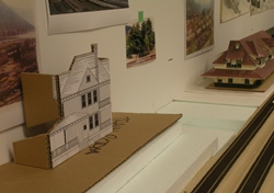 By building a cardboard mock up using the plans I determined that there was not quite enough space to accommodate the full depth of the building. A little experimentation which considered the overall topography and configuration of this area allowed the appropriate depth to be finalized and the mock up was modified for confirmation. (see photo).
 -
A copy of the plans were then marked up and supplied to Patrick who then embarked on building a beautiful model of this locally recognizable residence. As a MMR, Patrick employed several techniques, including 3D printing several components, to complete the model. It was painted in colors that are appropriate for the 1960 era. A photo of the house temporarily positioned is included here. Much scenery and other work needs to be completed before the structure can be permanently located.
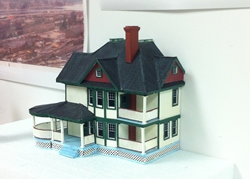
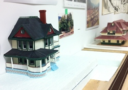
- October 4 - 7, 2016 | CPR Boundary Sub
Research Road Trip
 In July 2015 I had a very successful trip exploring portions of the railroad that I am modelling. At the time, a further trip was determined to be necessary, so off I went again in October of this year. My travels took me to Nelson, Salmo, South Slocan, Castlegar, Paulson pass and Grand Forks – a lot of territory to cover in 4 days.
Well, 2000 kilometers and many photos later, I had a lot more information to assist in advancing the layout along. Since I hope to model the fall, one of the objectives was to visually capture the fall colors that prevail in the Kootenay areas. A few photos are included in this entry.
I also drove over the old railroad grade – now part of the Trans Canada all-use trail – from the summit at Farron to Grand Forks and recorded the trip with lots of photos. This section of the Boundary Sub represents that next phase of the layout to be constructed.

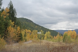
I also had the pleasure of spending some time in the Grand Forks city archives and acquired some data and photos to assist further. The archivist there was very helpful and told me they will be scanning a lot of photos over the winter to add to their collection.
 While in Nelson, I had the opportunity to stop by the newly restored Nelson C&W (CPR) station. Kudos to the community there, all their volunteers and corporate sponsors for doing a great job on preserving the building. A photo of the restored building included here.
- August 18, 2016 | CPR Boundary Sub
Phase II expansion implementation
In April this year we ceased operation on the layout so the main centre peninsula could be constructed. See the PENINSULA CONSTRUCTION UPDATE entry below.
-
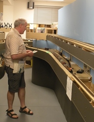 This expansion also triggered numerous revisions and updates to collateral items including; the Timetable, the Dispatchers Train Sheet, various train instructions, many waybills, layout schematics, and other misc items.
A significant part of the work was to also dismantle, move and reassemble the temporary west staging yard. In the process, it had to be cut apart and modified to fit along a wall that had a 15 degree bend in it. And, because one can never have enough staging, we added a fifth track to it as well. This yard will be moved at least once, possibly twice more before the mainline is completed.
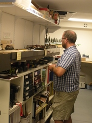
The 130 foot mainline extension was designed to capture the isolated section of the prototype line westward from Castlegar towards the summit at Farron. This section was a grueling 2+% ascending grade with numerous curves, tunnels and bridges. We only included 2 long sidings and a short section of a decommissioned siding that is now used as a OCS/MOW set out track. There are also no operator stations along this line, so trains are really on their own.
After several months of hard work and testing by a dedicated group of the host team, the project was completed sufficiently to permit resumption of operations. Consequently, we called for a session on August 18th to test this new section and garner constructive feedback from the regular crew that participated. Generally, the layout and equipment ran well technically, however, the first thing we learned was that we needed to increase the size of the road crew pool – kind of obvious in hindsight! Other suggestions related to several procedural items and support graphics. Another outcome was that it was now time to expand and improve the layout electronics by adding a booster and more breakers and a few other items. (yuck – electronic stuff – my least favorite part of the hobby!)
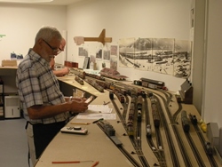
All in all we are pleased with the success of this phase of the layout. A few photos are included here – for more – refer to the Layout section under the Photos tab.
- April 27, 2016 | CPR Boundary Sub
The nelson station model
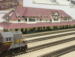 The Nelson station was built in the late 1800’s by the Columbia & Western Railway and subsequently served as CPR’s Boundary Subdivision offices until a few years ago. It has recently been repurposed into the Nelson chamber of commerce office and other related uses.
This structure is quite unique and is one of the iconic buildings on the Boundary Sub. For many years on both
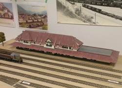 the previous, and the present layout a “temporary” foamcore model served as modest placeholder, until fellow modeller & friend; Patrick Lawson MMR, graciously offered to scratch build the building. His plans for the original C&W building were published in Mainline Modeller many years ago and provided a starting point for the project.
After several months researching what the c/a 1960 building would look like, Patrick produced plans relevant for that era and constructed the model from styrene. He used some interesting and creative techniques and jigs to build the custom windows and roof eave brackets – see photos. The building was custom painted based on colors appropriate for 1960.
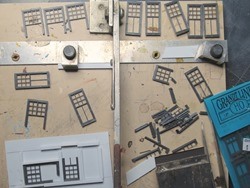
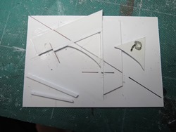
We are VERY pleased and honoured to have this handsome and completely prototypical CPR building on the layout. This will truly be the centrepiece of the yard area.
Compare the model to the photos of the actual station in the Prototype Photos section.
- April 19, 2016 | CPR Boundary Sub
GN Nelson Line progress
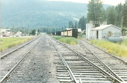 The layout is designed for several interchanges, including the GN line from Washington state that ran north from the border through Salmo, BC and connected with the CPR mainline 5 miles east of Nelson at Troup Junction (formally known as Five Mile Point). This line was originally Daniel Corbin’s Nelson & Fort Sheppard Railway (N&FS).
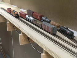 Today, track reached the northern end of the Salmo site, and several tracks were partially installed to permit limited operations from Nelson, through the unique Troup Junction and terminating at Salmo.
The configuration for the Salmo area on the layout very closely matches the prototype GN plan (see plan), although we are still researching some of the buildings that were located there. The line will pass through Salmo and terminate in a 3 track staging yard representing points south across the USA border.
 The Feb 12, 2016 posting featured the timber trestle that will be installed on this branchline.
 - April 9, 2016 | CPR Boundary Sub
first train through the helix
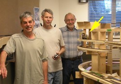 We concluded our work session this day by running a short freight train led by CP GP 9 #8523 from Coykendahl siding to Tunnel siding. This section of the mainline represents 80% of the 2900 foot long Bulldog tunnel. Construction of this area was originally reported on in the Feb 8th posting.
The photo is of the author, and crew members; Ken Catlin & John Martin with the train shown emerging out of the upper (west) portal of the tunnel (yellow arrow).
The helix is 30” radius, about 1 2/3 turns and a 4” lift per level. The actual hidden section representing the tunnel will be 26 ft long.
- April 2016 | CPR Boundary Sub
troup junction planning
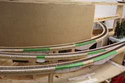 The Troup Junction area (formally known as Five Mile Point), on the prototype has a total of six modest wood frame trestles in close proximity; 4 GNR ones and 2 CPR ones. We have been experimenting with the layout and configuration of these trestles for many months and here is a photo showing the final planned configuration of the bridges.
Based on prototype plans, very helpful info on the KVR Blog by the Coquihalla Man; (.blogspot.ca/), and photos & field measurements taken by myself and fellow modeller; Brian Stokes, the CPR trestle at Mi 132.5 is completed as seen in the photo.
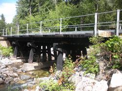
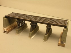
I got a little carried away, and included NBW’s, and other fine details that will probably not be visible once the scene is completed, however, it was good practice to refresh my modelling skills since I have not built many models in the last few years!
Click on the PDF to view the prototype plan of this junction.
- March & April 2016 | CPR Boundary Sub
peninsula construction update
During January & February, most of the framing was constructed for the large peninsula that would carry the 130 foot long phase II mainline extension from Castlegar to a location just east of the summit at Farron. This is the first of the major grades into the mountains and varies between 1.5 & 2.2%.
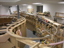
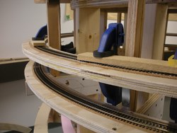
Laying the flex track & shinohara turnouts, and the installation of the bus wiring and feeders for this section progressed through March & April. Although this phase adds a significant distance to the mainline, it will only include the sidings at Coykendahl & Tunnel, and a former siding – now MOW spur track at Porcupine.
All track is code 70 by Micro Engineering, and is glued down with white glue. We had great success with this approach on the previous layout. There are several areas where the curvature is extremely broad and we used a length of spline as a guide to draw the centre lines which were used to lay the track as shown in the photo. We also used metal track guides for the 36” R curves.
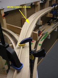

- February 12. 2016 | CPR Boundary Sub
PLANNING THE VARNEY TRESTLE INSTALLATION
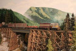 In mid-2007 the late Gordon Varney, MMR scratch built a substantial wood frame trestle based on plans prepared by myself utilizing prototype CPR drawings. (see photo) This spectacular trestle & surrounding scenery was a signature scene on the previous layout, and was featured in the RMC article on the layout in June 2013.
Since there were no remaining wooden trestles on any of the CPR subdivisions we model in 1960, it was a challenge to find an appropriate location to showcase this wonderful model as a memorial to a very good friend and outstanding modeller.
During the redesign of the GN Third Subdivision, we realized that the longer branch line would now have sufficient length to accommodate one or perhaps two of the wooden trestles that still exist on this now abandoned line.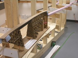

The next challenge was determining how to fit the curved structure into this narrow section of the layout considering the bench work is only 10 to 12” wide in this area. There was actually only one location on this shelf where the line curves, although not as much as the bridge did.
In order to ensure a smooth track flow over the bridge and through the adjacent topography on both ends, a cardboard bridge template was fabricated for initial planning purposes (see photo). Once we were satisfied that the bridge would fit, a spline section was built over the cardboard template (see photo), and it was then used as part of the actual GN branch line spline construction. This strategy proved very workable and created a smooth alignment of several curves in the track.
- February 8. 2016 | CPR Boundary Sub
HELIX & Road bed construction
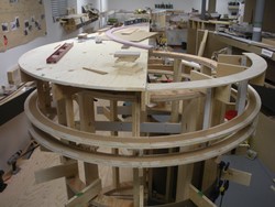 The final design for the mainline over the Monashee Mountains includes a modest 1 2/3 turn helix between Coykendahl and Tunnel sidings. This helix was also positioned at the point where the prototype 2900+ ft Bulldog Tunnel is located in the plan.
Because the helix will be hidden, we chose a 30” radius, even though the design mainline minimum is 36” for the layout. We felt that preserving aisle space was more important than maintaining the minimum 36” radius which was not visible or critical. The line gains over 6” in elevation, and is approximately 27 ft long through the helix. We were very pleased with this outcome since this tunnel is the longest one on the southern mainline, and ours is 80% full length. In addition, the alignment of the track and tunnel portals on both ends reflects the prototype very accurately as well.
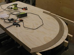

Having never constructed a helix, I reached out to the local modelling community as well as the Layout Construction Yahoo group for feedback and ideas. This is an wonderful hobby for the sharing attitude so many of modellers possess, and I gained a great deal of knowledge from these exchanges. It was actually surprising that there was very little published on how to design and construct a helix.

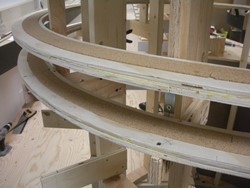
As a result, we settled on what we are calling an “inside out” helix design. One of the big drivers in the design was to eliminate the need to build the helix from inside a structure, or to have to crawl inside a structure to access the helix. So, we built a 4 ft diameter 2x4 stud frame cylinder and hung the helix off the outside of these curved walls. The helix sub roadbed is 2 layers of 3/8” finish grade plywood with offset joints and glued together, with a thin cork roadbed layer on top for sound deadening. (see photo)
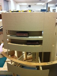 In our opinion, significant lengths of hidden track create access challenges as well as psychological anxiety for operators when trains cannot be seen for any length time. To address these concerns, the exterior fascia that encloses the helix will have several viewing slots that are intended to represent cut-aways of the “tunnel”. There are several excellent versions of this idea out there, so this is not an original idea.
Because the major framing for the helix is set back from the outer face of the layout by 8 to 10”, this design also freed up space on the lowest deck (which represents the GN line), to expose a lot more of this line before it enters the staging yard than originally contemplated. The 30” radius for this line is exposed at this level; however, it satisfies the minimum branch line standard.
We have received numerous questions and inquiries about this aspect of the layout and will therefore post a more detailed commentary with supporting sketches, etc in the Techniques section of the web site at a later date, so check back if you are interested. Meanwhile, we have included a few progress photos below. - January & February. 2016 | CPR Boundary Sub
peninsula construction
Due to the size of the layout and the priority given to hosting op sessions, the current layout ends with a temporary west end staging yard. See previous entries for more detail on this point.
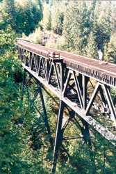 Towards the end of 2015, we decided it was time to commence the next phase of the layout which is to include the mainline climbing west from Castlegar to the summit at Farron in the Monashee Mountains. This section of the line includes a 2% ascending grade and is intended to capture the true isolated “feel” of this area of the Boundary Sub. It is also where the CPR employed pushers during the steam era.
Although a lengthy 130 feet of mainline is being added, there will only be 2 major sidings and one abandoned siding which now serves as a MOW set-out spur track. This phase will contain numerous tunnels – most close to prototype length and configuration, and the major 400+ foot long& 120 foot high steel bridge over McCormack Creek which will be modelled full size!
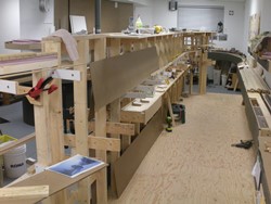

This section of the layout contains some of the most complicated framing, including the helix for Bulldog Tunnel. Several full size framing mock ups were completed and assessed over the last couple of years before settling on a strategy for the vertically cantilevered framing for this peninsula. This area also includes a 6” high raised floor along the internal aisle for the full length of the peninsula.

 After receiving a delivery from Home Depot for the majority of the framing materials, work commenced in early December 2015 with a crew of four. There have been numerous work sessions and a couple were recorded by John G on power point presentations – click on these links below to view these.
This peninsula will include the divisional Midway yard on the upper most deck at an elevation of 60” above the raised floor. It is actually almost the west end of the layout, and after this current phase of construction, there is another 170 feet of mainline to actually reach this location.
The lowest level of the peninsula contains the GN Third Subdivision, and we have included a couple of bridges, including the one built by Gordon Varney. The town of Salmo, BC will be modelled relatively accurately (although compacted lengthwise) at the end of the peninsula before the track wraps around the end and terminates in the staging yard.
There has been great progress on this phase with work now progressing on the spline roadbed for the mainline.
The temporary west end staging yard will be removed and relocated near the summit just east of Farron once this next section of the mainline is ready to put into service. -
- September 11 / 12 / 13. 2015 | CPR Boundary Sub
VANRAIL 2015 OP SESSIONS
.jpg) The Boundary Sub Ver. 2 successfully hosted 3 back to back 4 hour long op sessions as part of the VanRail 2015 Operation weekend that takes place every second year in greater Vancouver. This was our 5th event, and was attended by 37 very talented guests from all over Canada and the USA. The event web site is www.vanrail.ca if you would like to see more about it. Go to the operations photo gallery under the Photos tab to view more images of the sessions.
The Boundary Sub Ver. 2 successfully hosted 3 back to back 4 hour long op sessions as part of the VanRail 2015 Operation weekend that takes place every second year in greater Vancouver. This was our 5th event, and was attended by 37 very talented guests from all over Canada and the USA. The event web site is www.vanrail.ca if you would like to see more about it. Go to the operations photo gallery under the Photos tab to view more images of the sessions.
.JPG)
.JPG)
- September 11. 2015 | CPR Boundary Sub
FAREWELL TO THE KMR
.jpg) During the evening social gathering hosted at our home as part of the VanRail event, we had an opportunity to celebrate the contributions to the event and the local hobby in general by Brian and Margaret Pate. The over 60 folks that were in attendance enjoyed sharing a cake that featured a an image of #102 northbound on the Homestake Gulch trestle on the KMR narrow gauge layout. The Pates will be moving this fall and as a result both the KMR and CPR layouts are being dismantled & demolished so we took advantage of this large gathering to wish them well and thank them.
During the evening social gathering hosted at our home as part of the VanRail event, we had an opportunity to celebrate the contributions to the event and the local hobby in general by Brian and Margaret Pate. The over 60 folks that were in attendance enjoyed sharing a cake that featured a an image of #102 northbound on the Homestake Gulch trestle on the KMR narrow gauge layout. The Pates will be moving this fall and as a result both the KMR and CPR layouts are being dismantled & demolished so we took advantage of this large gathering to wish them well and thank them.
.jpg)
.jpg)
- September 6. 2015 | CPR Boundary Sub
WEST STAGING YARD RELOCATION
.JPG) The temporary West staging yard was relocated today. Since it was originally installed, I was always thinking I should have moved it further down the wall. So, because I work well under pressure and often do things somewhat last minute, on September 6th with the assistance of a couple of my regular crew, we unbolted the 12 foot long yard which was cantilevered off the wall, disconnected the bus wiring, removed the fascias and literally carried it 15 feet and re-installed it at the end of the room. It was shifted down the wall of the room to separate it more from Castlegar and elongate the mainline by about another 15 feet to make it slightly more than 200 feet overall now.
The temporary West staging yard was relocated today. Since it was originally installed, I was always thinking I should have moved it further down the wall. So, because I work well under pressure and often do things somewhat last minute, on September 6th with the assistance of a couple of my regular crew, we unbolted the 12 foot long yard which was cantilevered off the wall, disconnected the bus wiring, removed the fascias and literally carried it 15 feet and re-installed it at the end of the room. It was shifted down the wall of the room to separate it more from Castlegar and elongate the mainline by about another 15 feet to make it slightly more than 200 feet overall now.
.JPG)
.JPG)
New extended bus wiring and fascia was installed, and several pre-built plywood modules were screwed to the wall to infill the gap created when the yard was moved. We then temporarily installed and wired Micro Engineering flex track on plywood roadbed and powered things back up. It was all done in about 5 hours!
- August 18, 2015 | CPR Boundary Sub
SLOCAN WYE & TRACKAGE
.JPG) After enduring the hassle of an incomplete wye and associated trackage for many months, the South Slocan wye was completed as well as 2 temporary tracks for the mill and car barge at Slocan City in the adjacent room. This will provide more interest to the way freight turn that switches this area on the layout.
After enduring the hassle of an incomplete wye and associated trackage for many months, the South Slocan wye was completed as well as 2 temporary tracks for the mill and car barge at Slocan City in the adjacent room. This will provide more interest to the way freight turn that switches this area on the layout.
.JPG) The car barge location is currently a simple stub track for now, and the mill is a single track with a painted building mock up representing one of the major buildings in the plant. This temporary work will eventually be removed and replace with a much larger area to house the mill and the actual car barge slip in the future.
The car barge location is currently a simple stub track for now, and the mill is a single track with a painted building mock up representing one of the major buildings in the plant. This temporary work will eventually be removed and replace with a much larger area to house the mill and the actual car barge slip in the future.
- August 2015 | CPR Boundary Sub
NELSON YARD EXPANDS
.jpg) Nelson yard has been growing over the last several months as we continue to add new tracks and increase local switching opportunities. This month it was double ended by the installation of numerous turnouts in the east yard ladder. In addition, several east end switching spurs were added to make the yard more interesting and create more local work for the yard crews
Nelson yard has been growing over the last several months as we continue to add new tracks and increase local switching opportunities. This month it was double ended by the installation of numerous turnouts in the east yard ladder. In addition, several east end switching spurs were added to make the yard more interesting and create more local work for the yard crews
.JPG) The yard currently has most of the double ended yard tracks and approximately 75% of the local switching tracks. Next up will be the ancillary tracks for the scale, stockyard & clean out tracks, as well as the complicated tracks feeding the diesel shop. Once these additions are completed, the yard will be able to function as the division point as per the prototype.
The yard currently has most of the double ended yard tracks and approximately 75% of the local switching tracks. Next up will be the ancillary tracks for the scale, stockyard & clean out tracks, as well as the complicated tracks feeding the diesel shop. Once these additions are completed, the yard will be able to function as the division point as per the prototype.
- July 2015 | CPR Boundary Sub
ROAD TRIP THROUGH THE KOOTENAYS
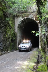 During a trip to southern BC, we stopped in at Castlegar to visit some folks involved in the maintenance of the former railway grade which is now a mixed use trail. We learned that vehicle access was permitted to the portion of the trail between Castlegar and Fife BC. So, on the way back to Vancouver, we took a 5 hour detour and drove over this section and took hundreds of photographs. This was a great research occasion with the ability to drive through all the tunnels, and over all the steel bridge spans. We are already using the photos to help develop the scenery and “feel” of various areas on the next phase of the layout.
This was an incredible opportunity and we really need to extend a word of thanks to the many volunteers that take care of this rugged piece of railway grade tirelessly. We have included a few photos here, and will post more in the Prototype Photos section over time.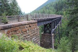
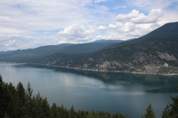


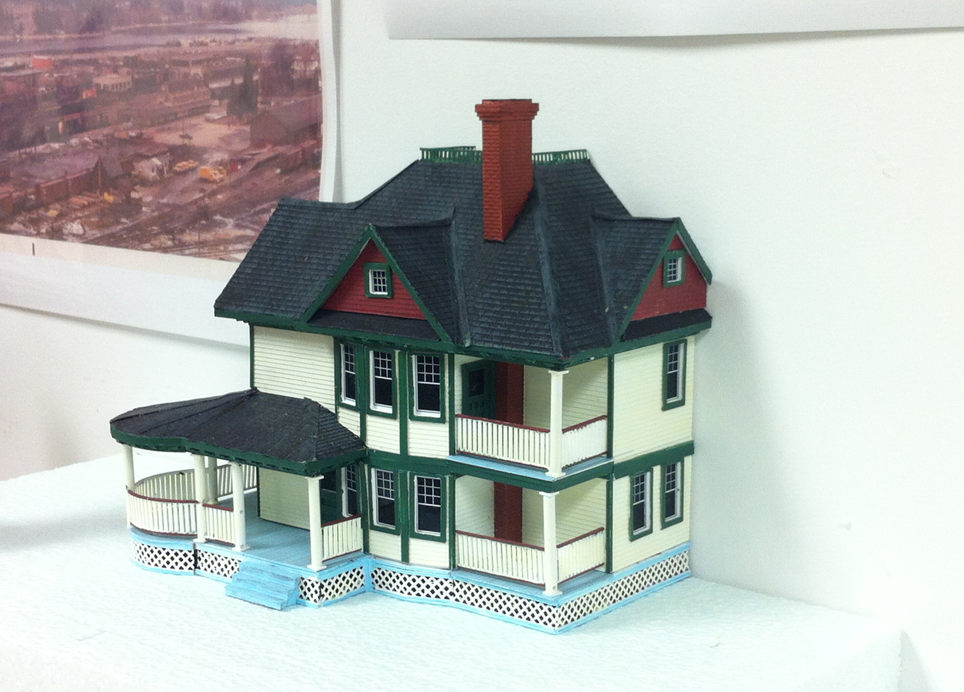

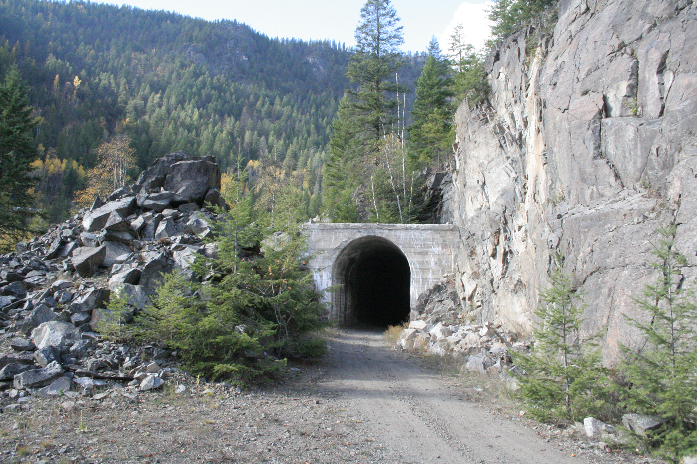
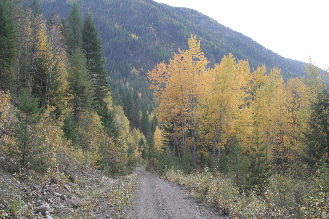

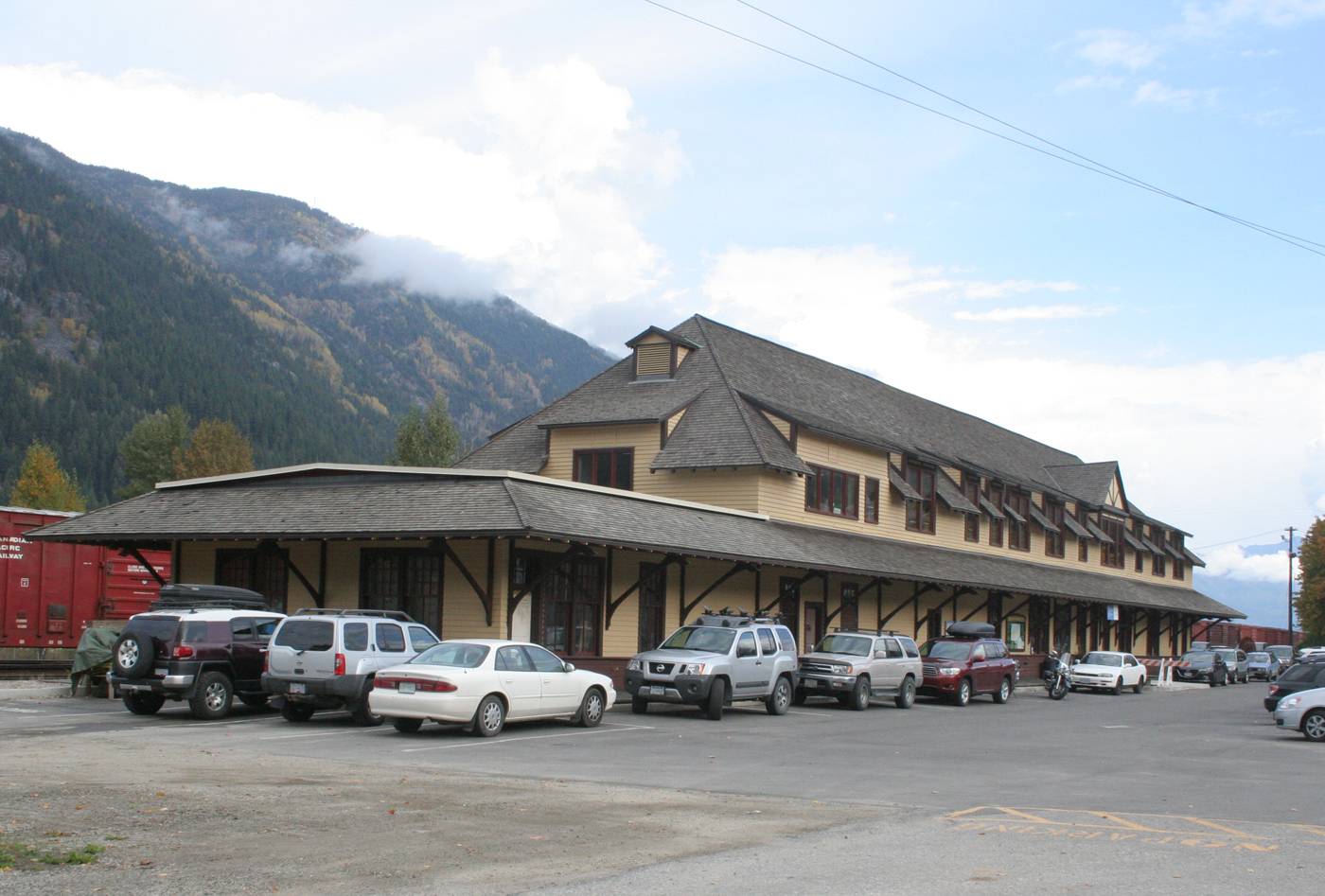
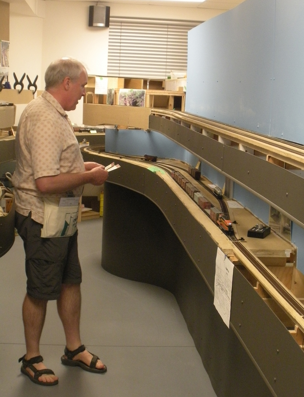
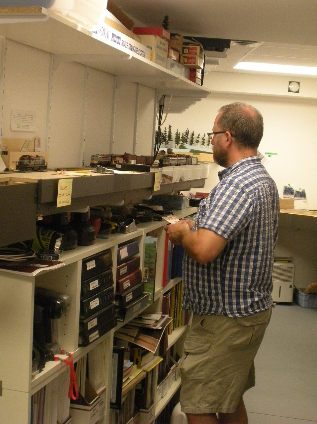

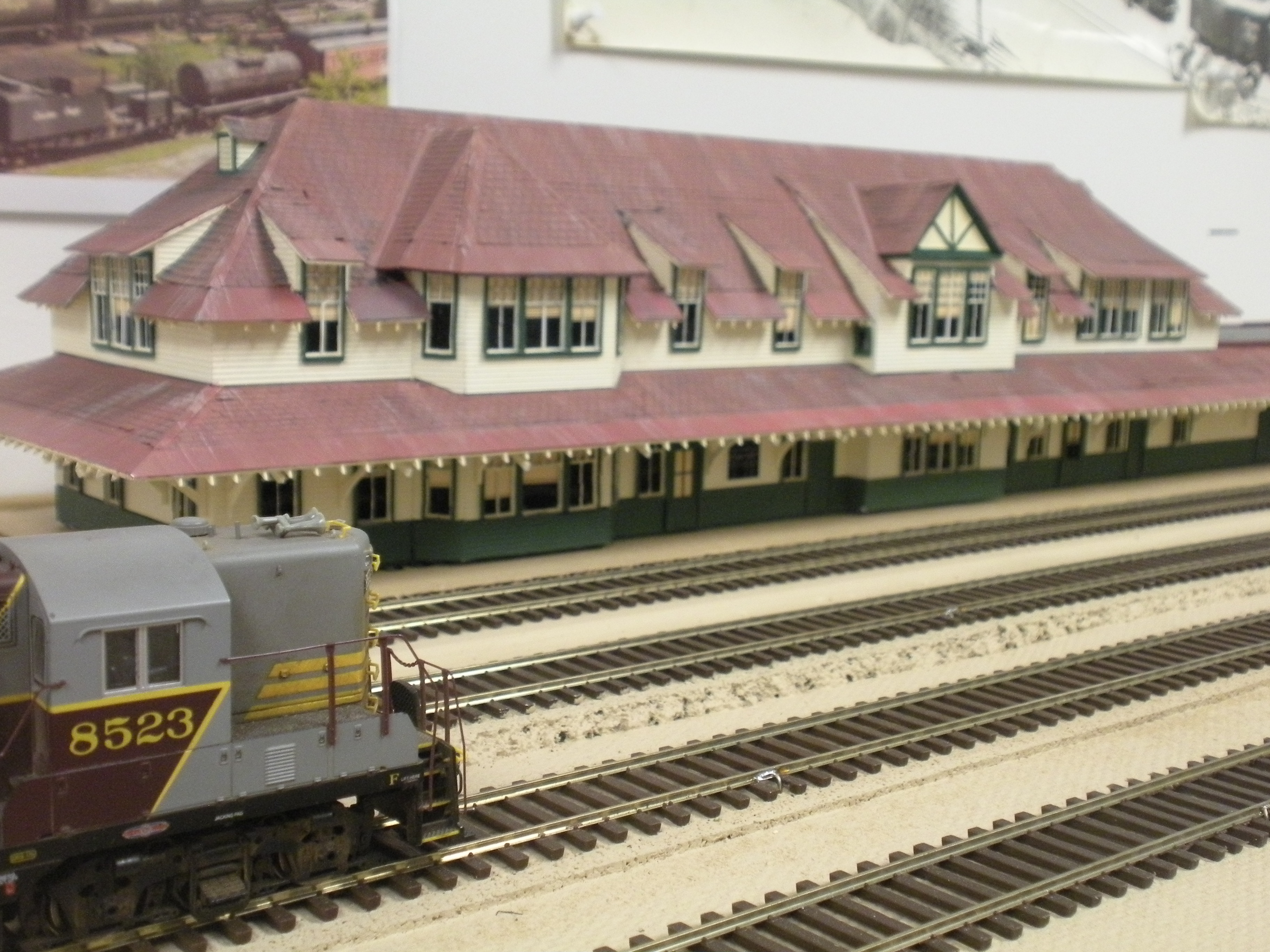
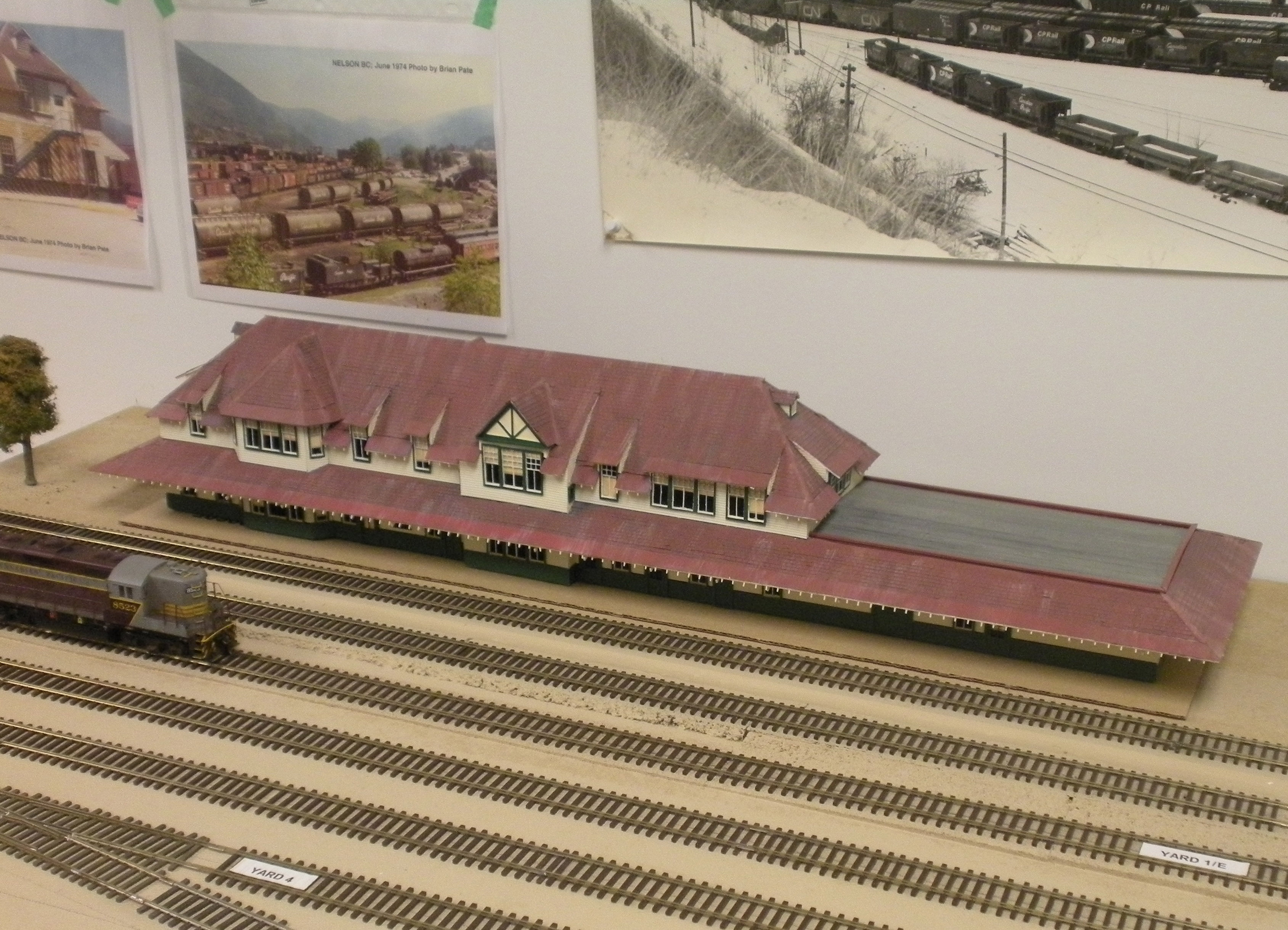
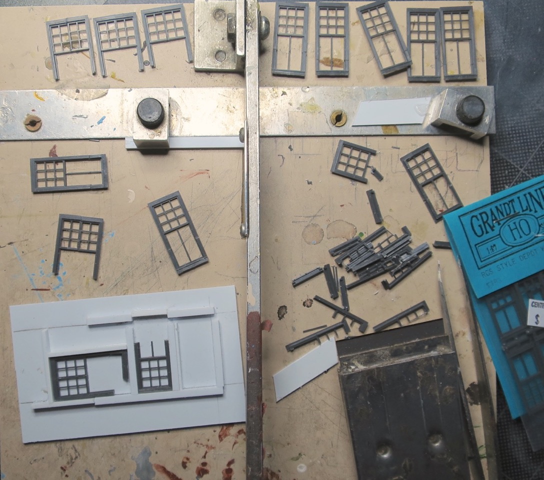

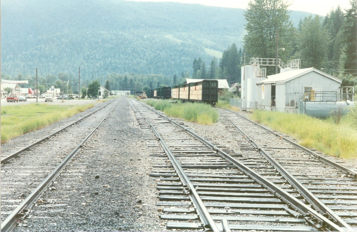
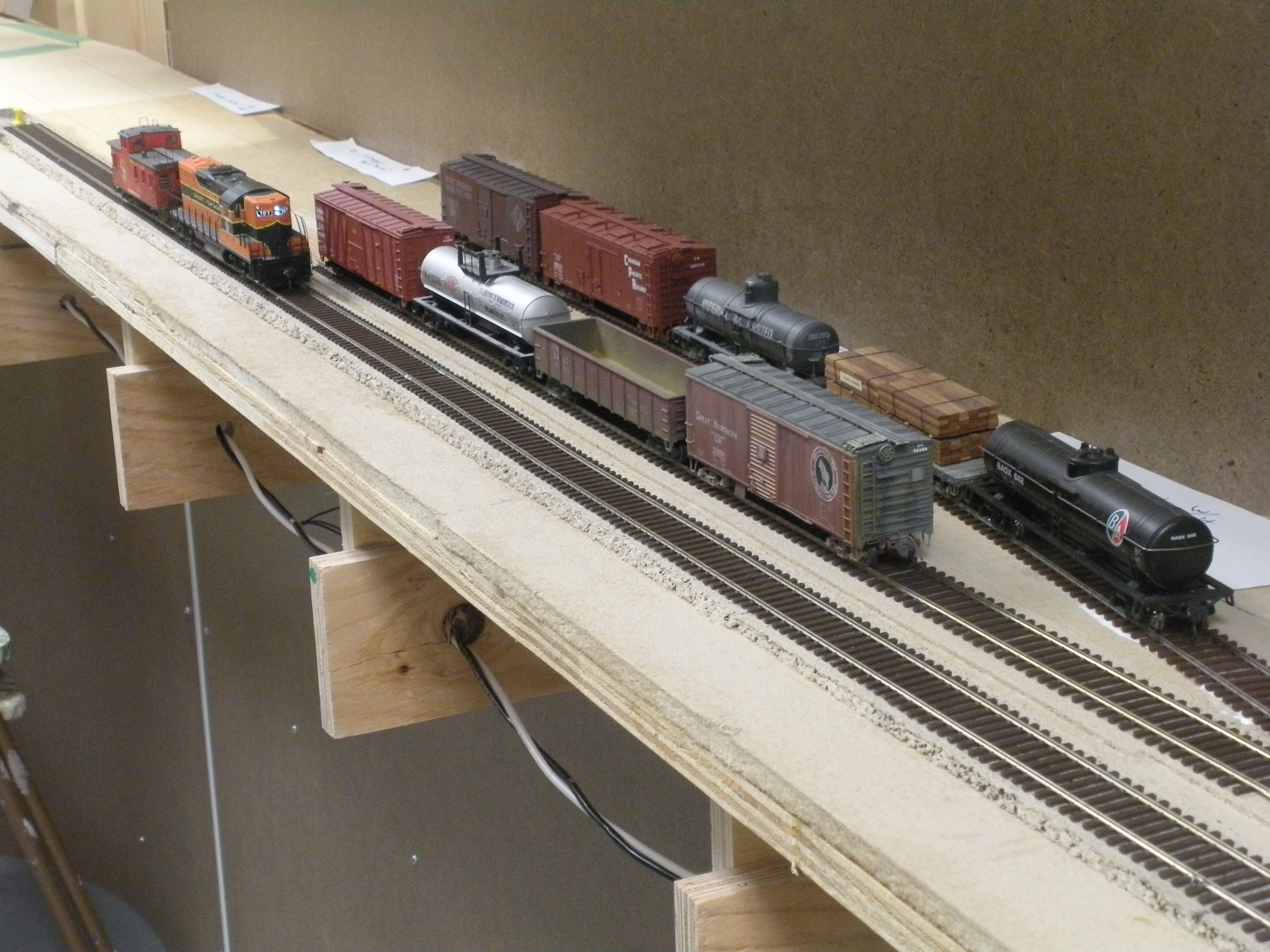
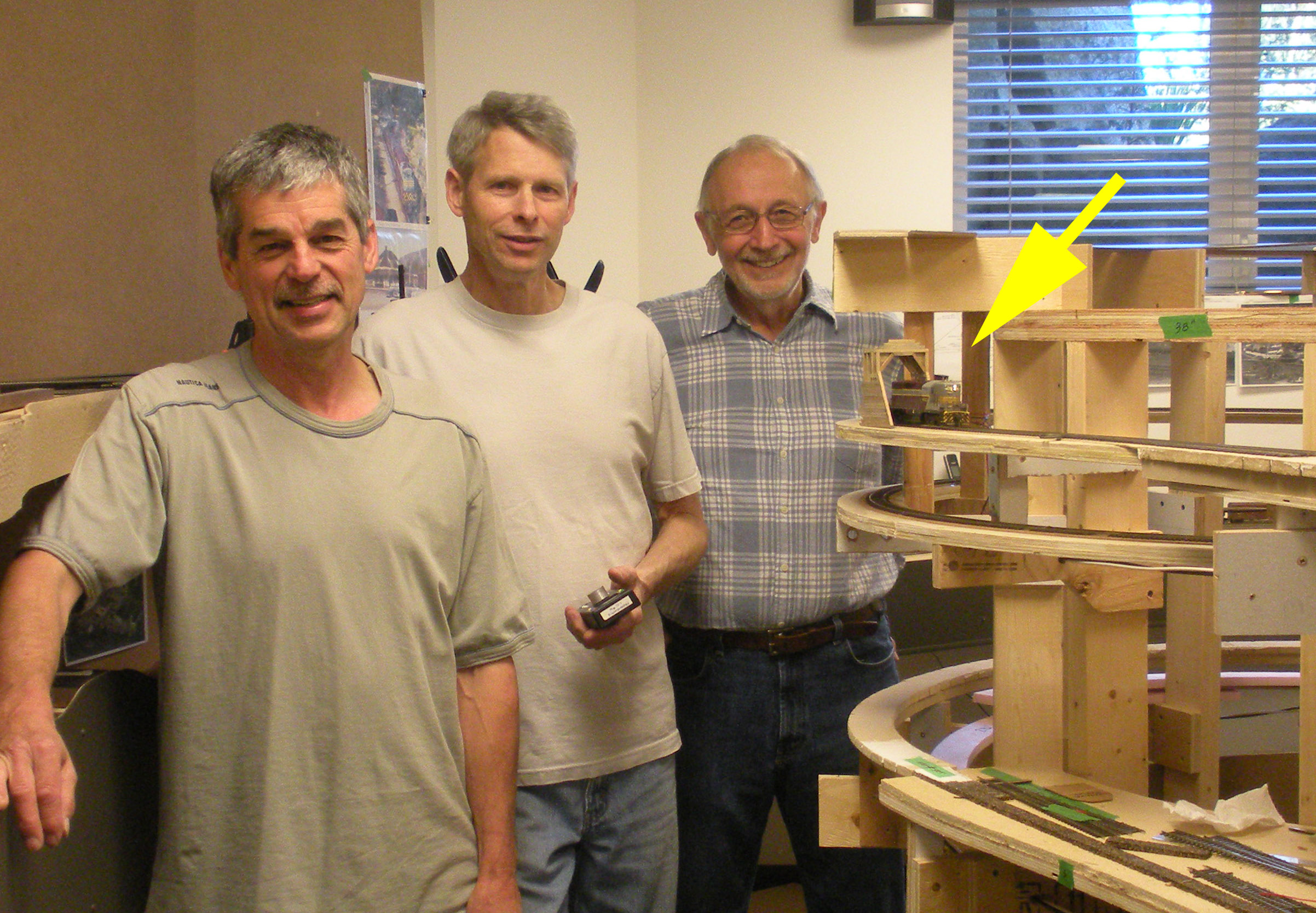

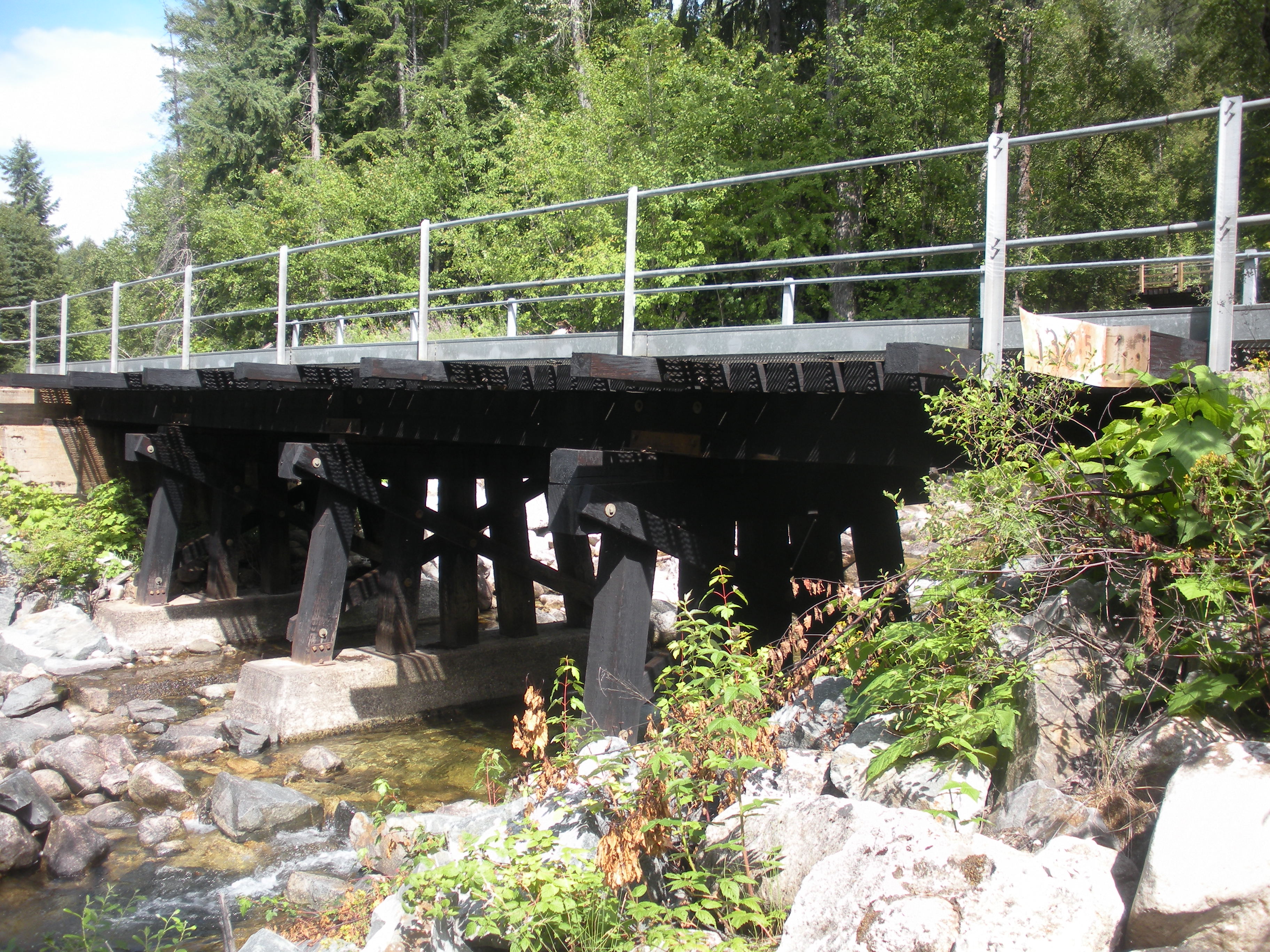
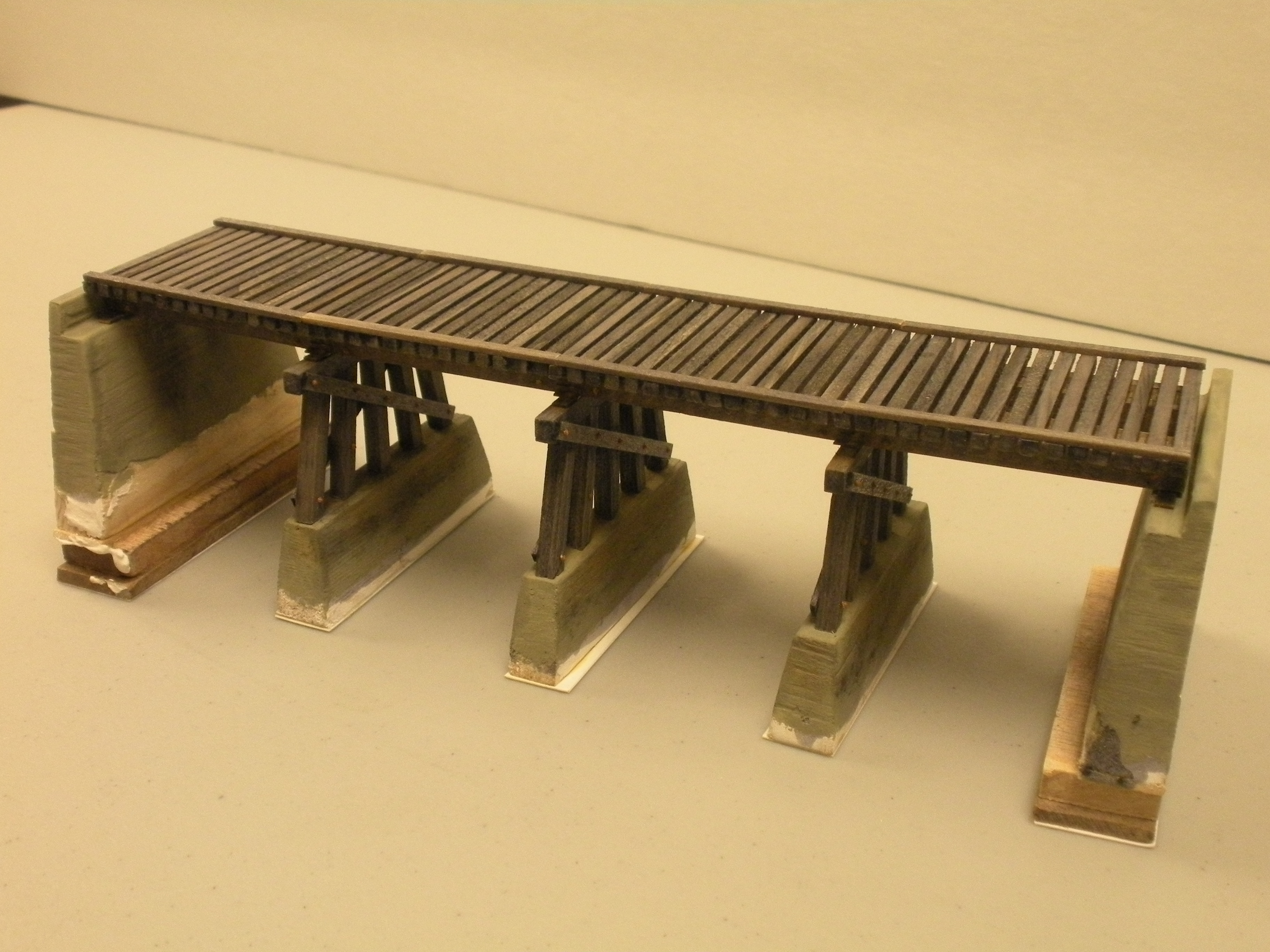

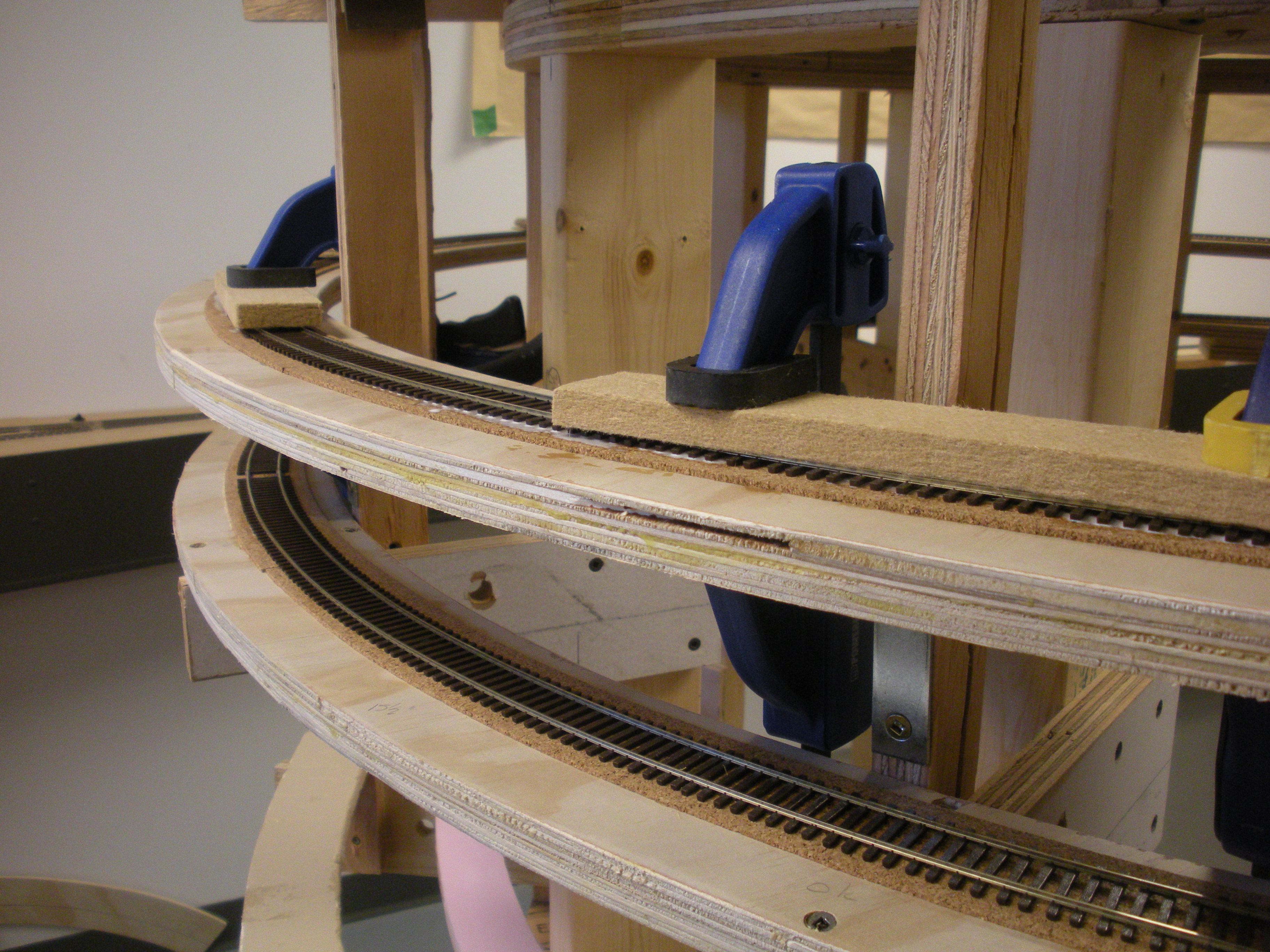
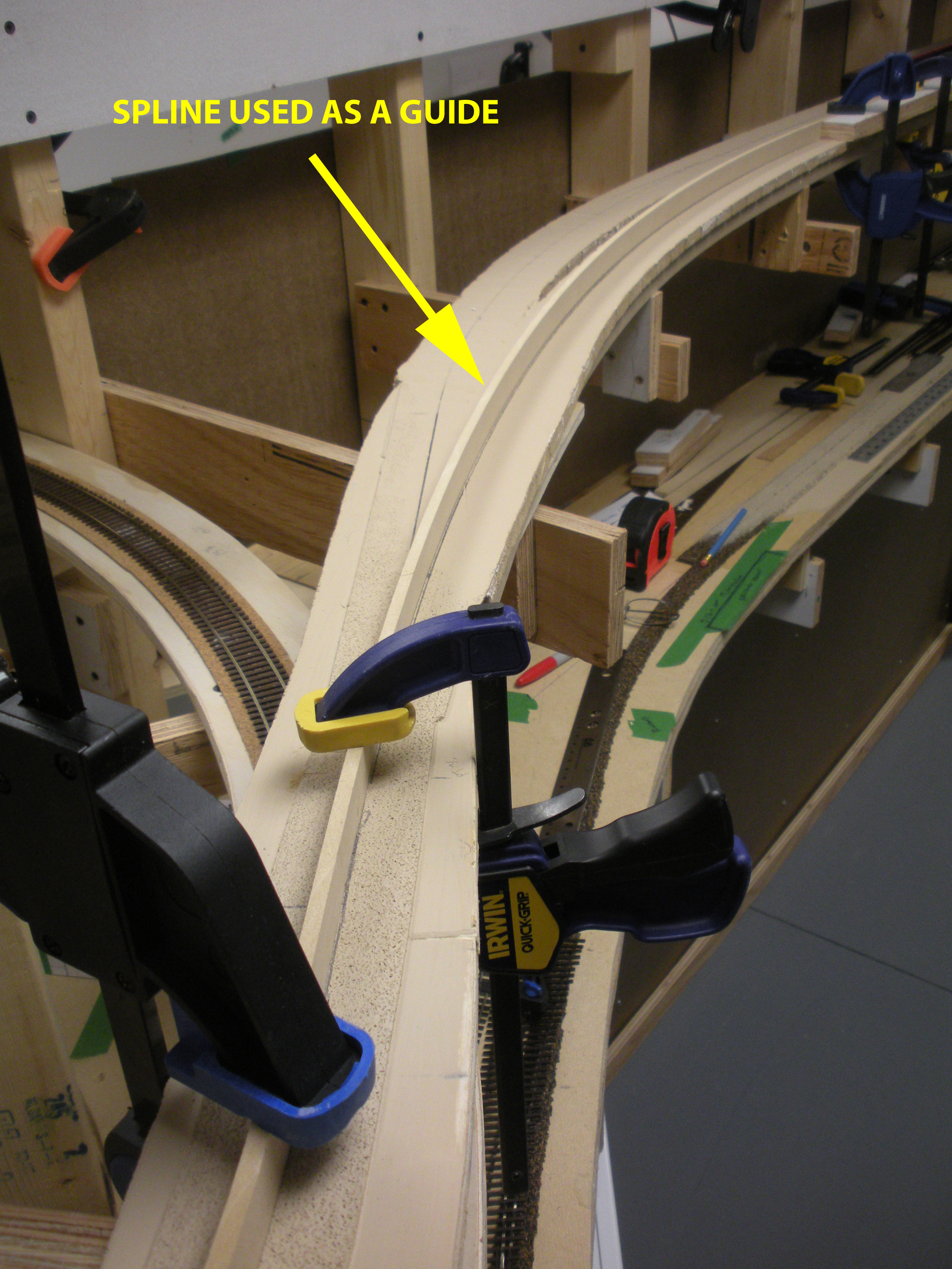
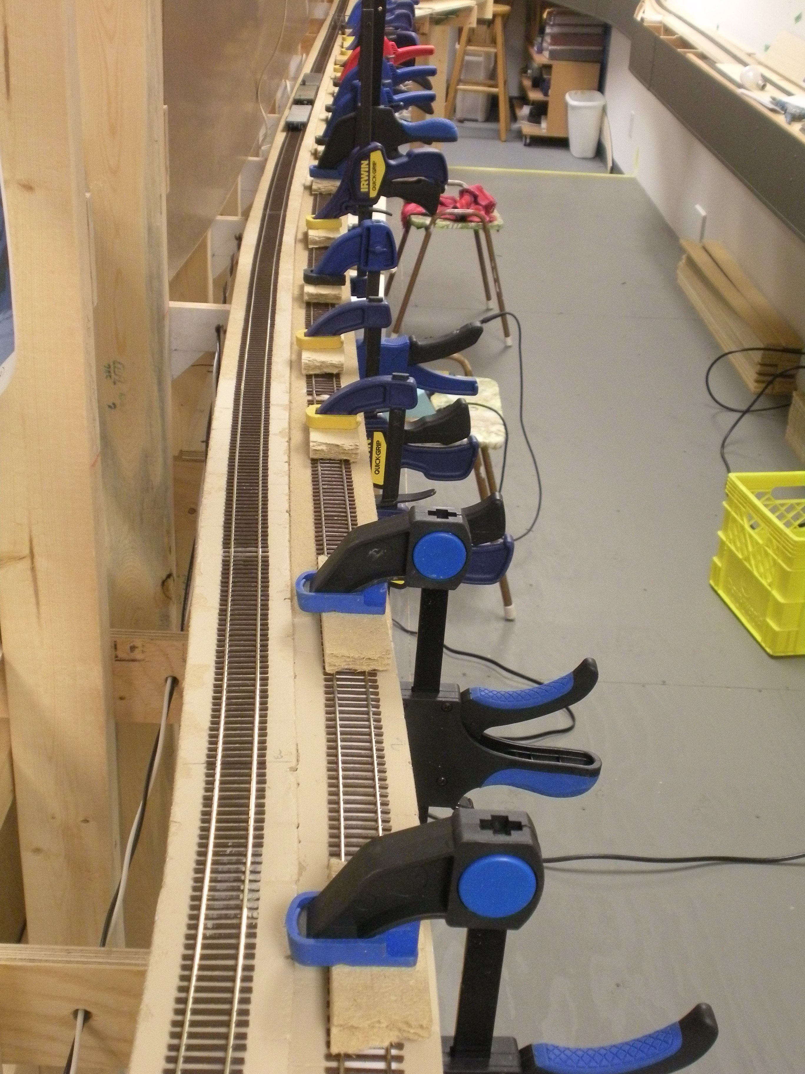

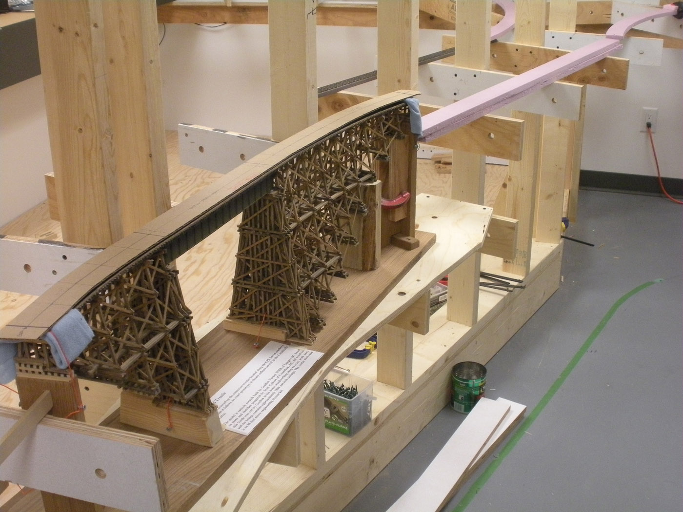
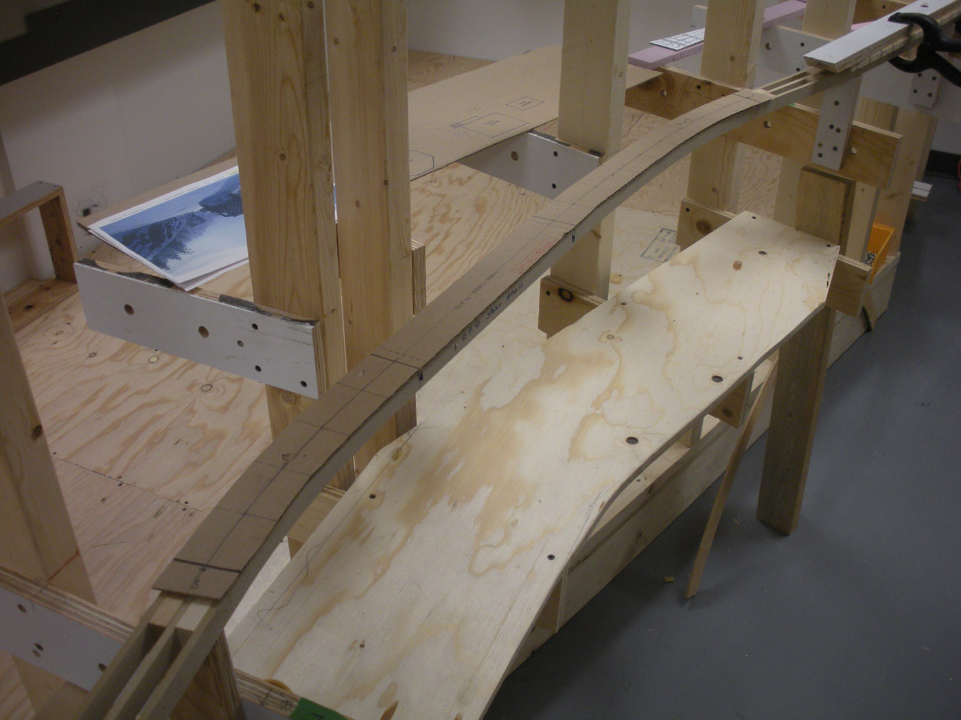
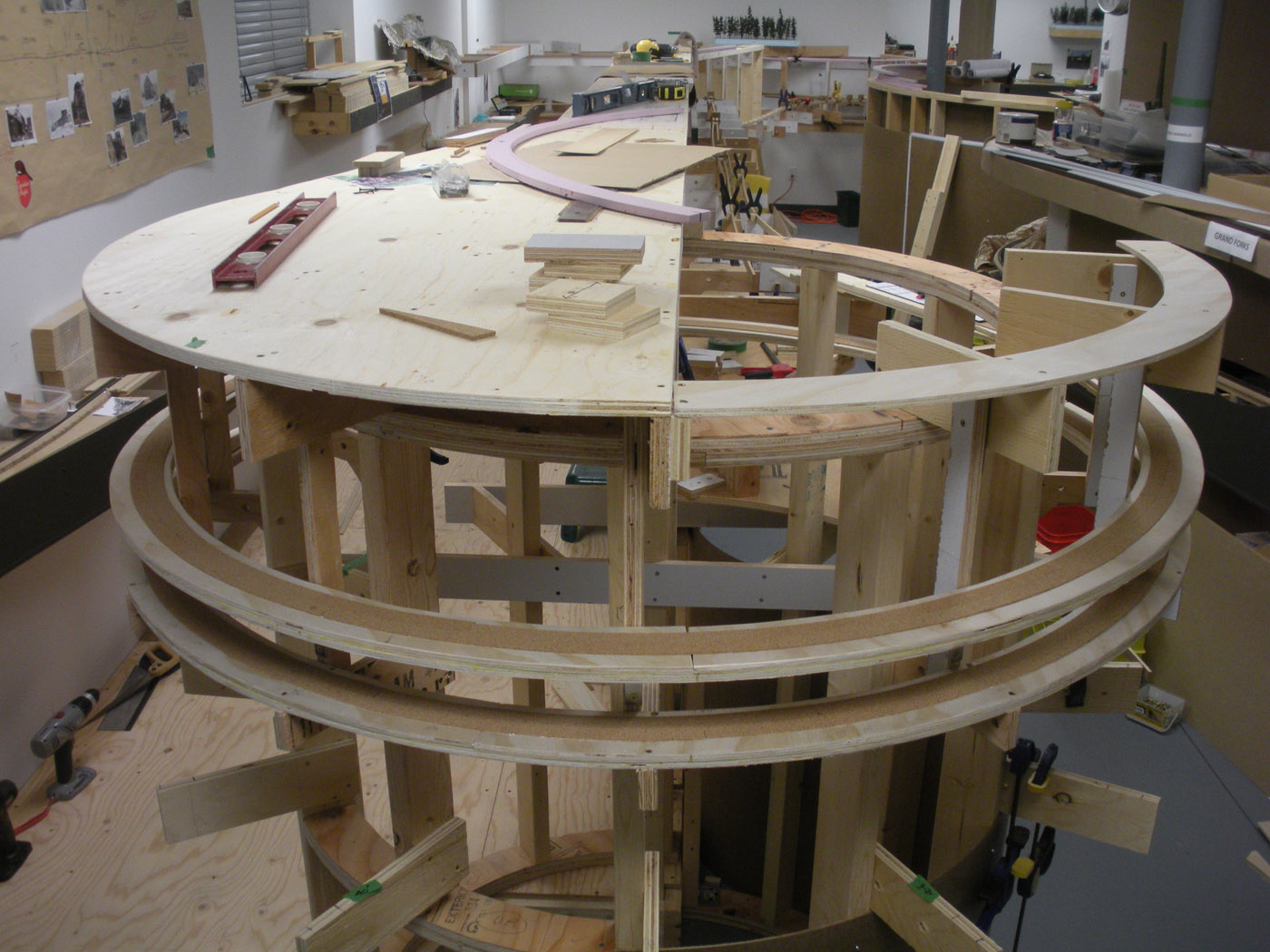
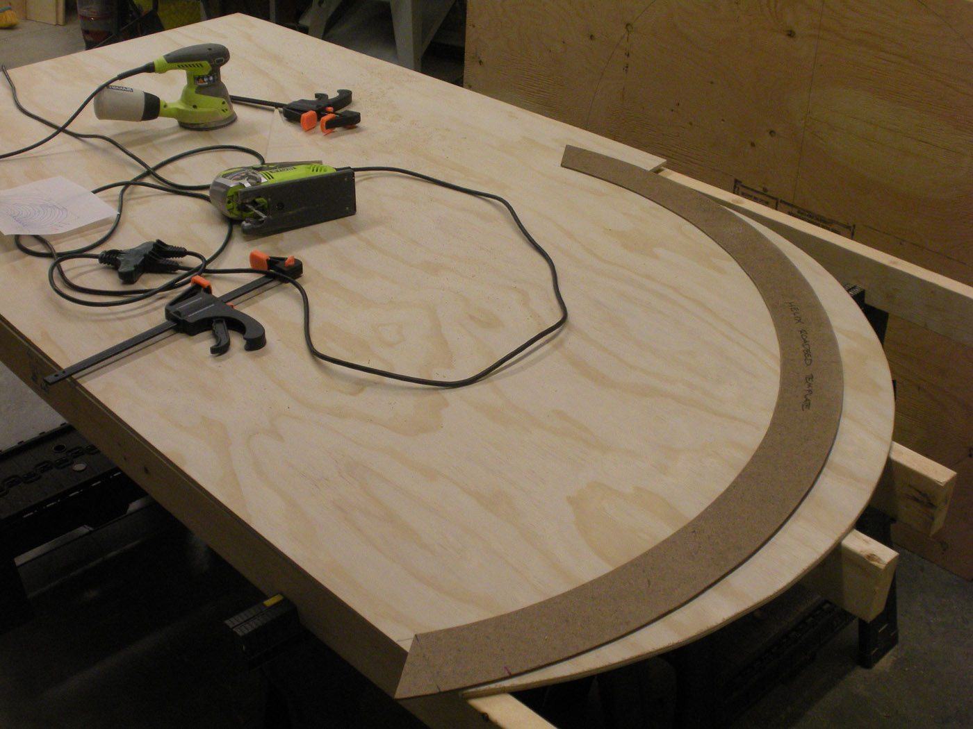
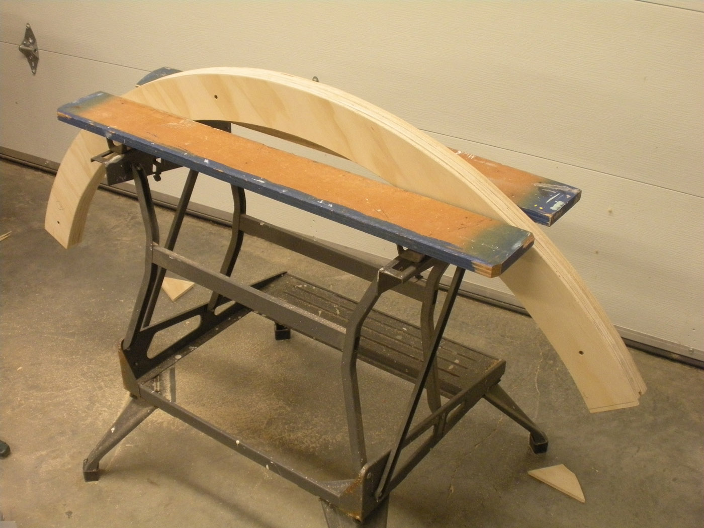
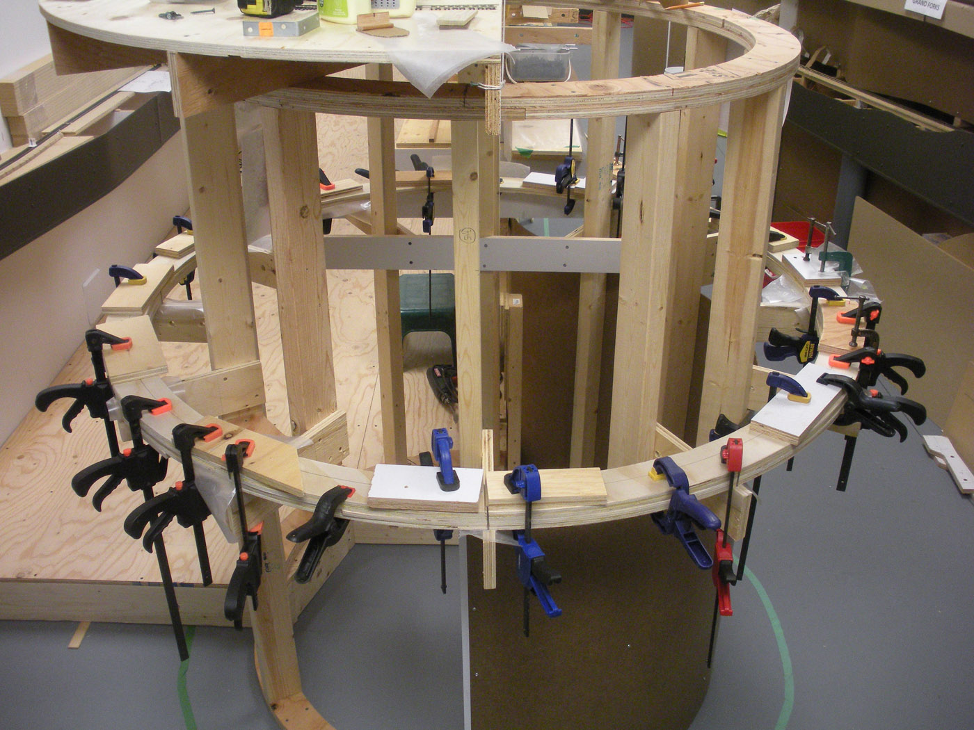
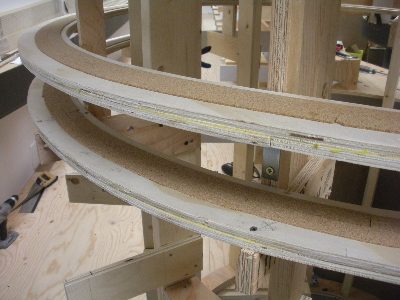
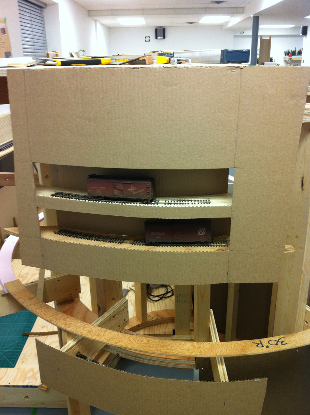
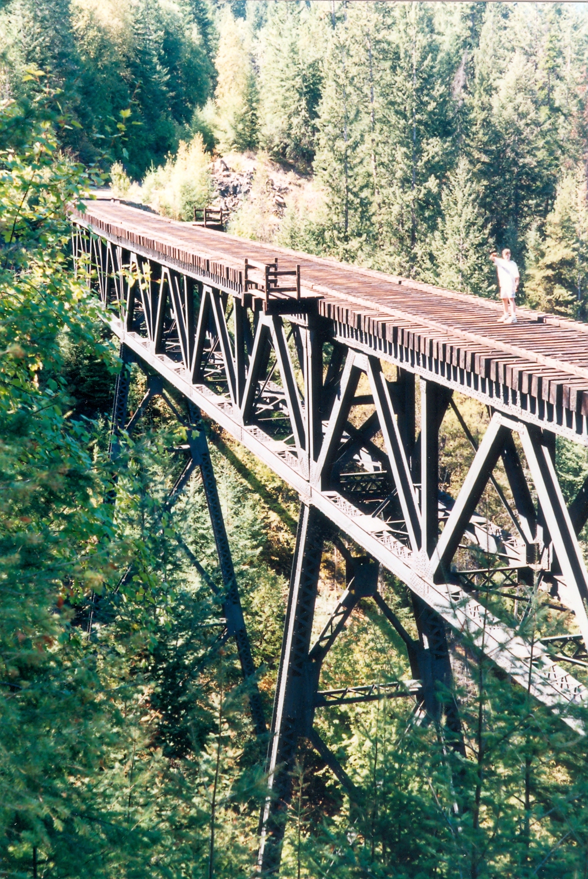


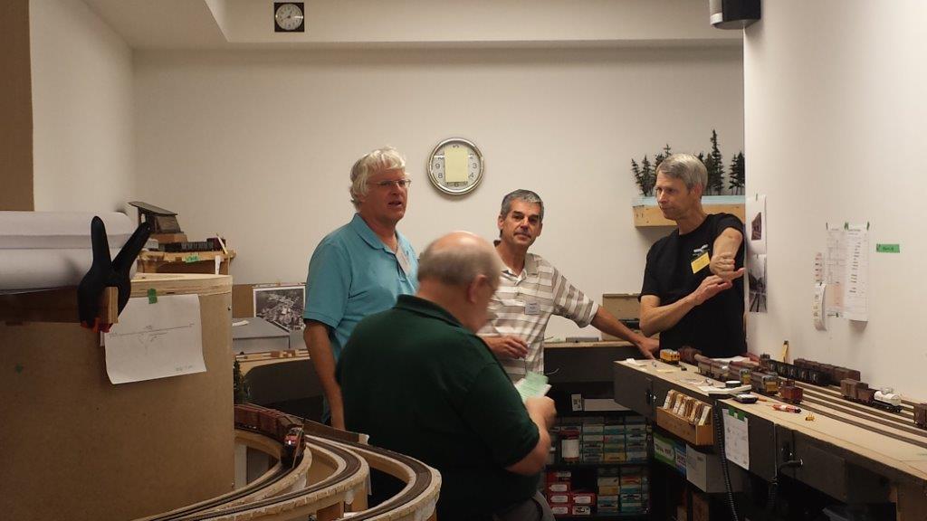
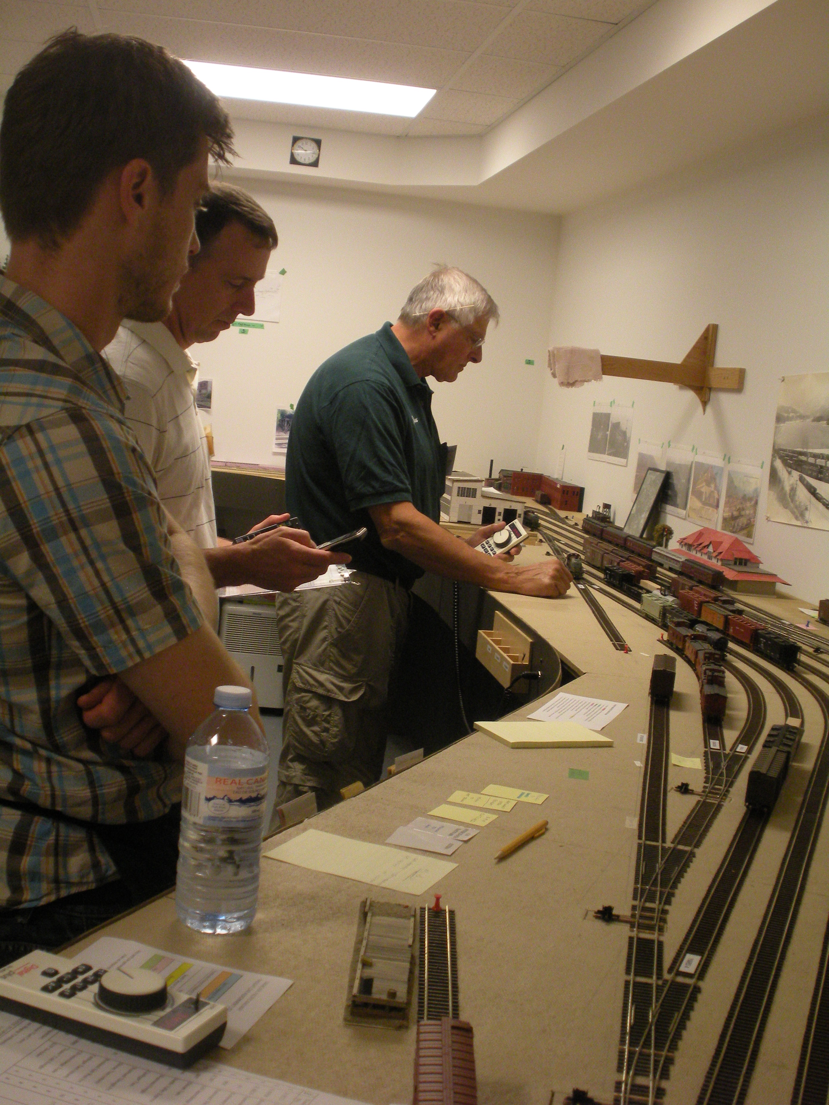

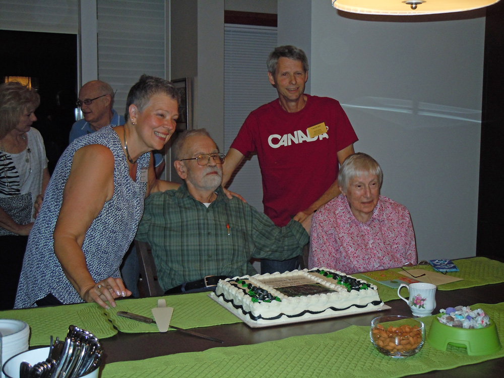
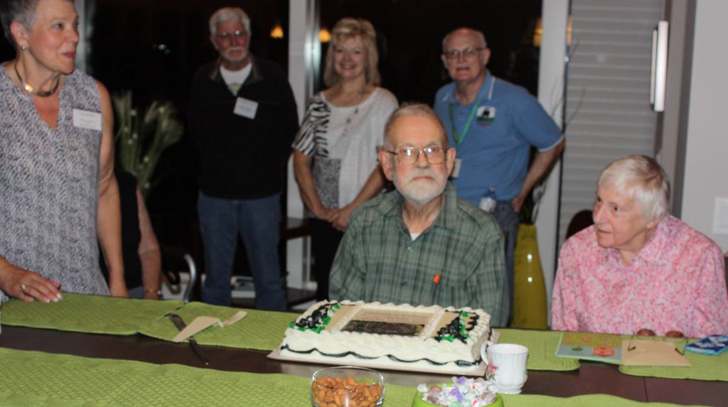
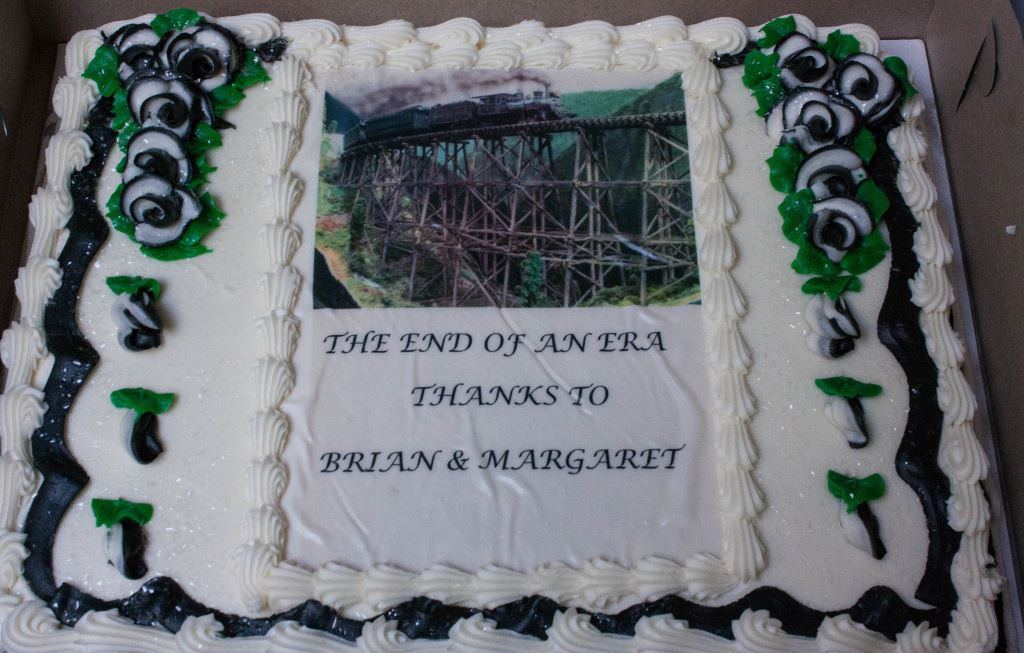
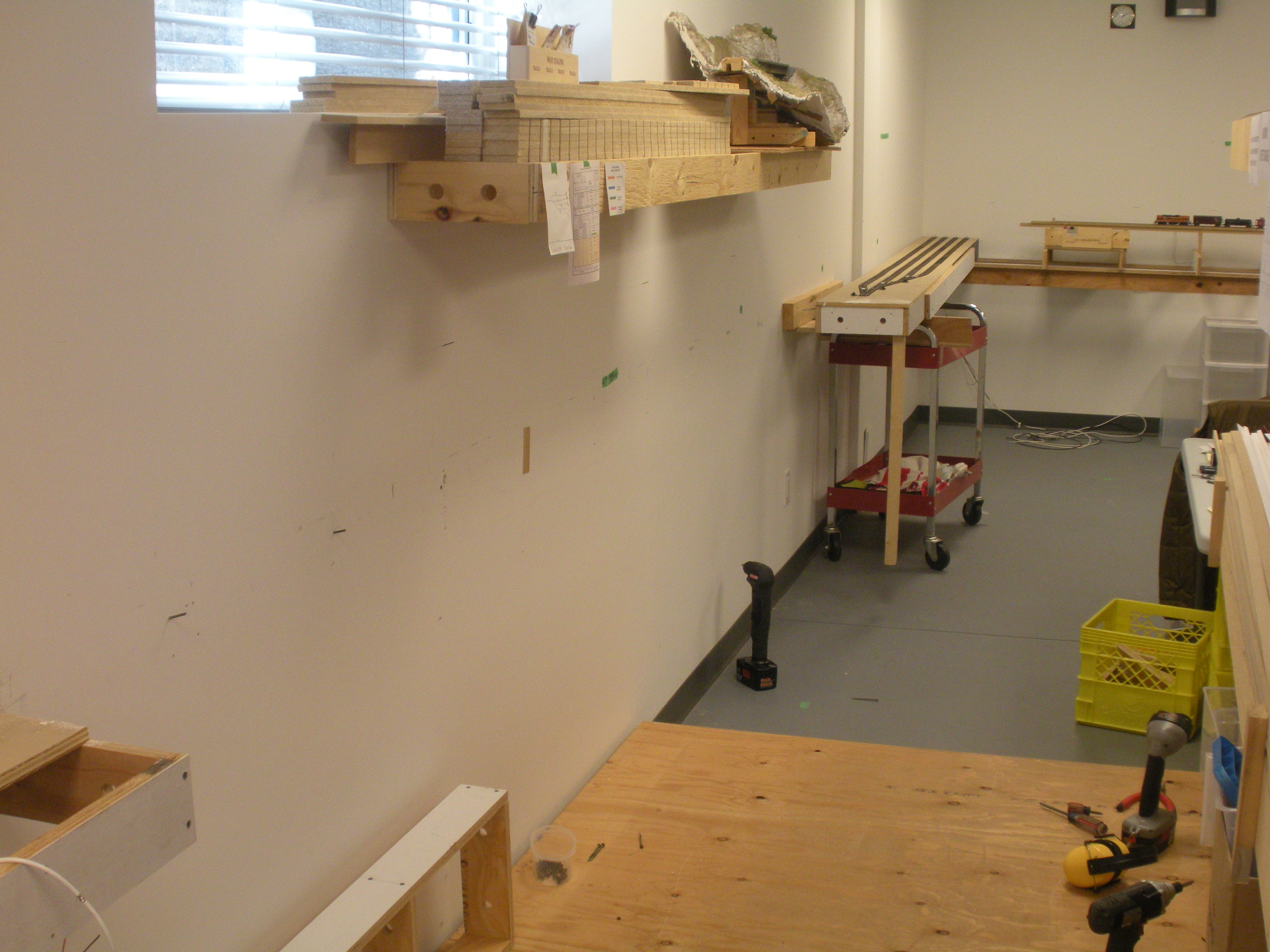


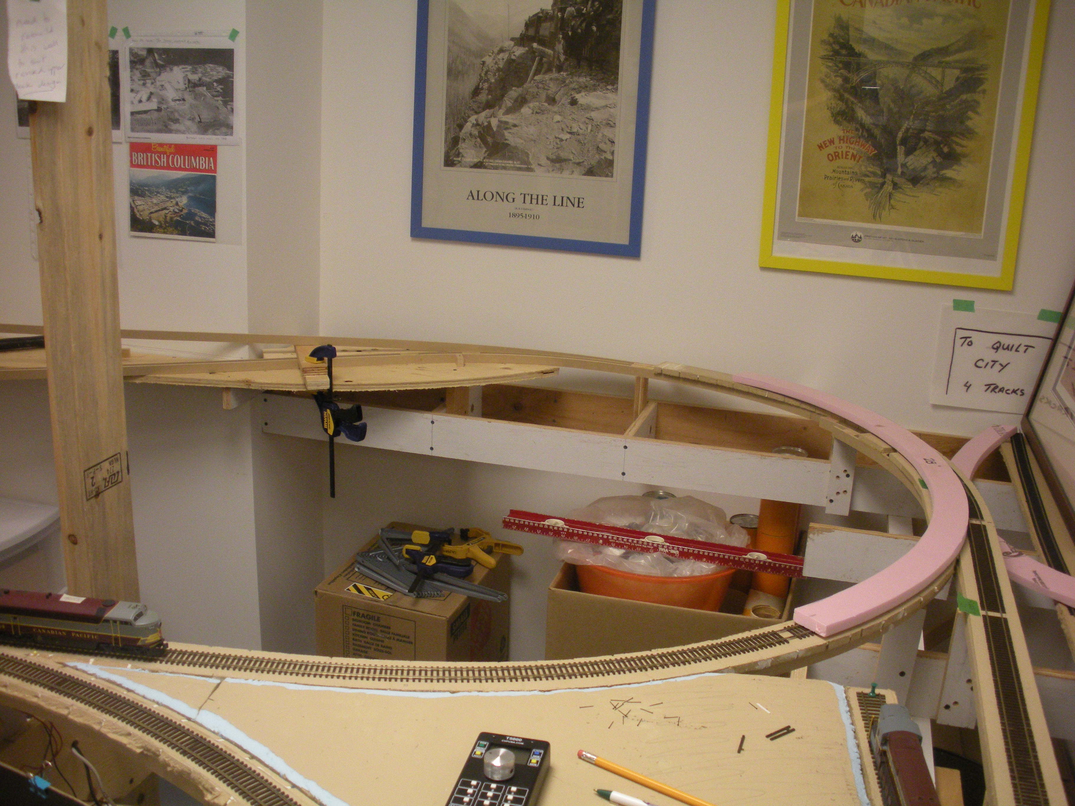

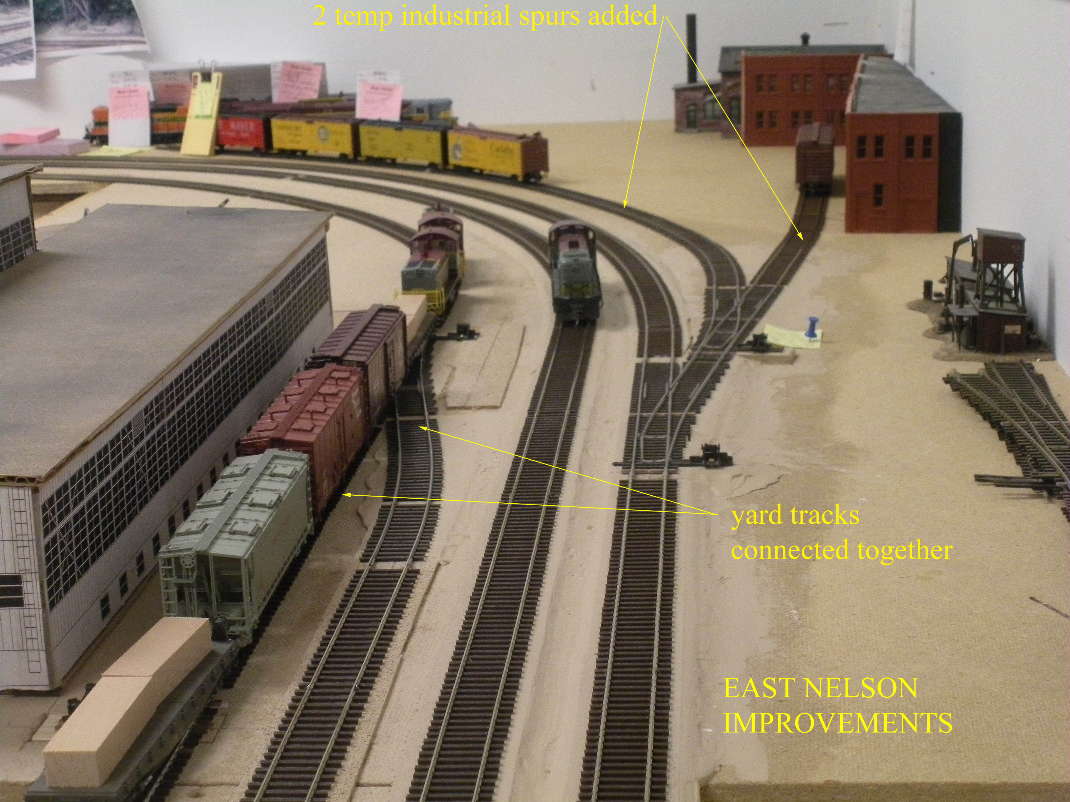
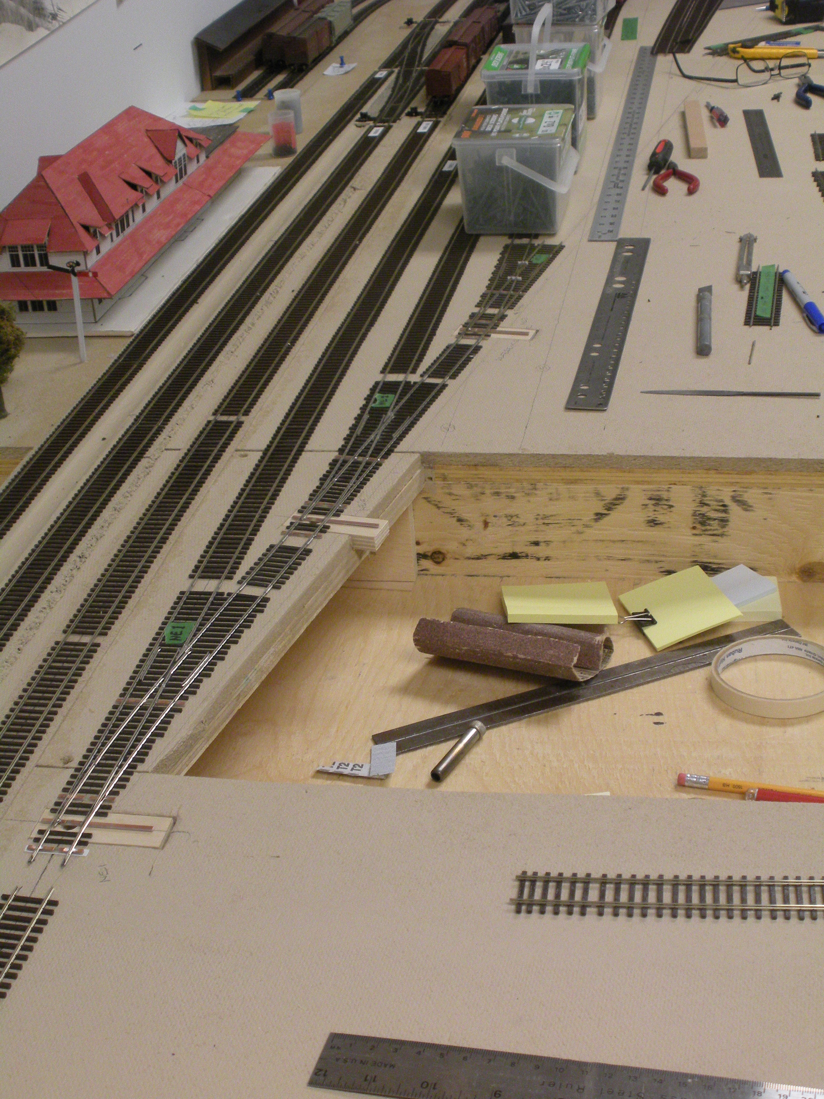
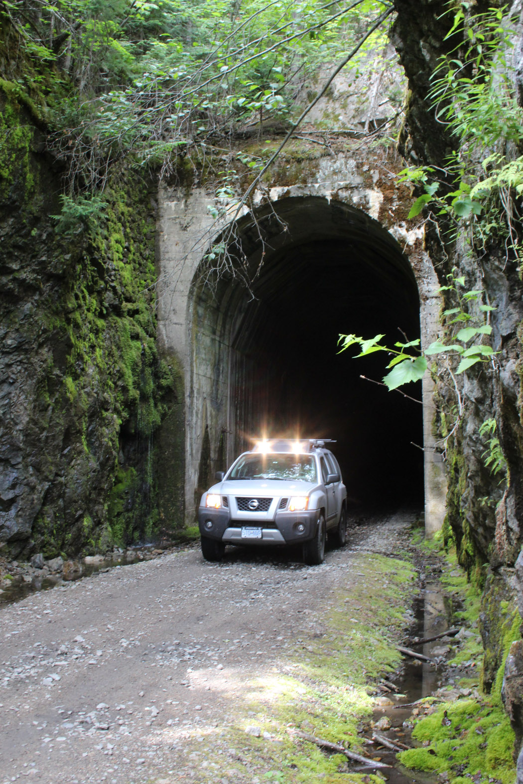
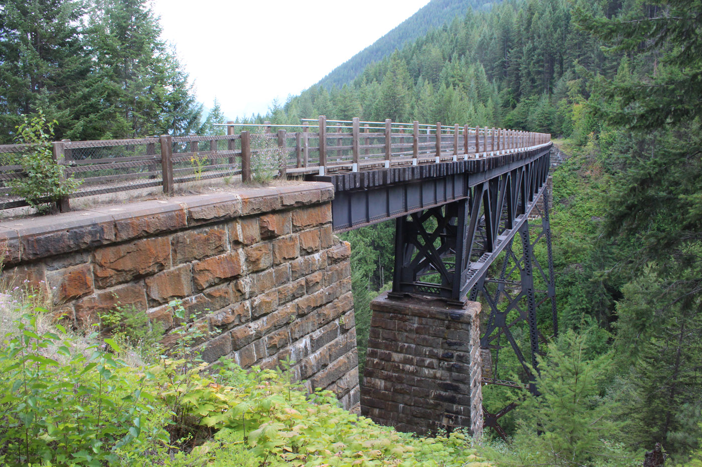

- July 2015 | CPR Boundary Sub
GN INTERCHANGE INSTALLED
.JPG) The GN trackage representing the GN 5th Sub was extended beyond Troup Junction into an adjacent area of the layout room to create an actual staging track for the train and to allow crews to perform the complicated caboose drop and runaround move when entering the CPR mainline at this location.
The GN trackage representing the GN 5th Sub was extended beyond Troup Junction into an adjacent area of the layout room to create an actual staging track for the train and to allow crews to perform the complicated caboose drop and runaround move when entering the CPR mainline at this location.
.JPG)
.JPG) This staging track will be realigned and extended down the yet to be built centre peninsula to create more on-line activity before the train terminates in the staging tracks.
This staging track will be realigned and extended down the yet to be built centre peninsula to create more on-line activity before the train terminates in the staging tracks.
- May 3, 2015 | CPR Boundary Sub
Inaugural op session
.jpg)
A mere 3 years after the construction commenced on the Boundary Sub II, we are pleased to have hosted the first formal operating session on the layout. This event represents the culmination of a lot of hard work by many people, and the realization of one of the primary objectives; start operating the layout as soon as possible.
This session places the initial 175 feet of mainline into use and relies on a temporary staging yard at the west end of the layout – which can be dismantled and relocated as the mainline advances up the 2% grade to the west.
The session was dispatched by Ken Catlin, and utilized full TT&TO and a 4:1 fast clock. 10 trains were run over a session that lasted a little less than 3 hours. The session was followed by a celebratory meal to commemorate the event.
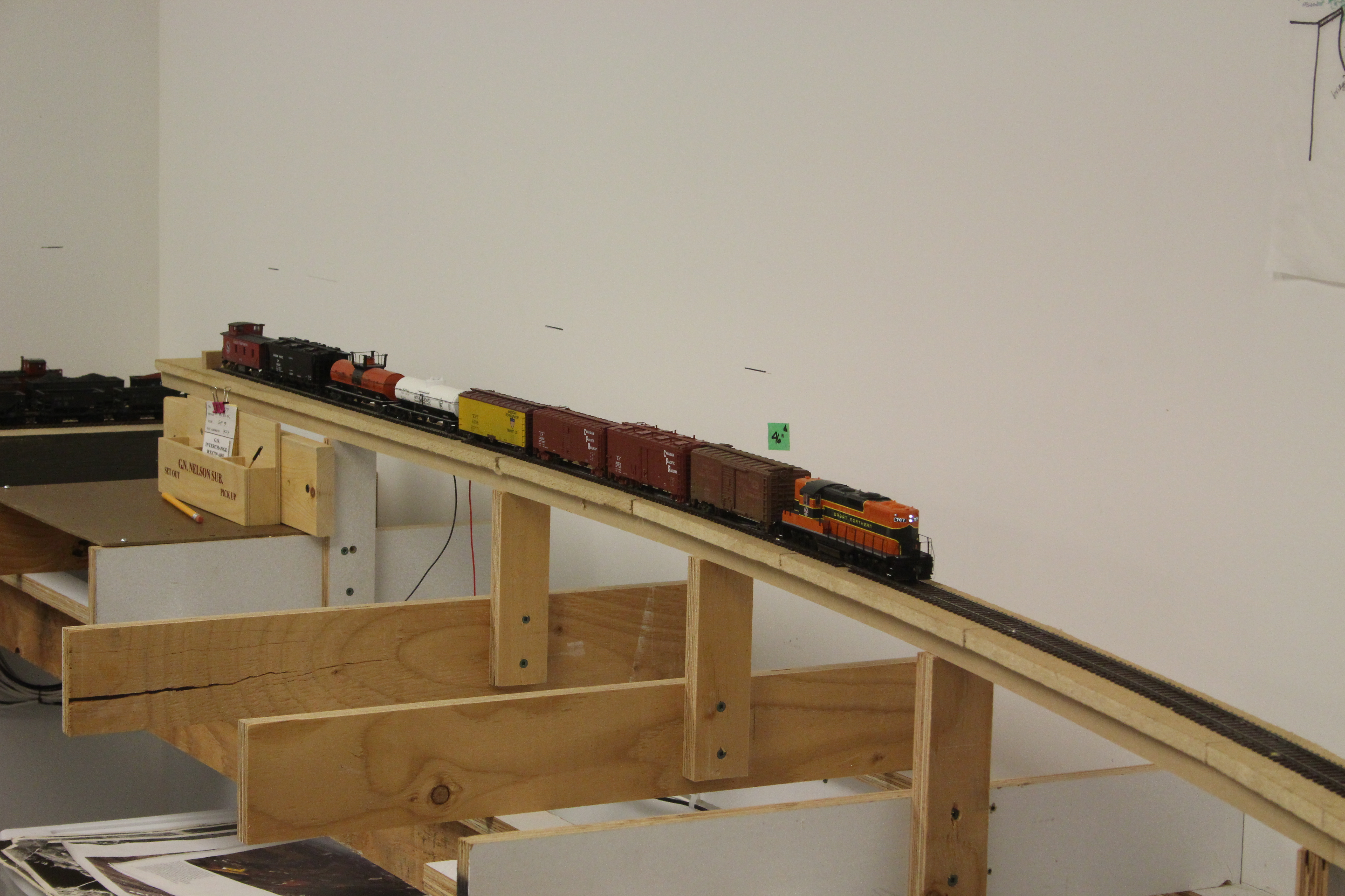
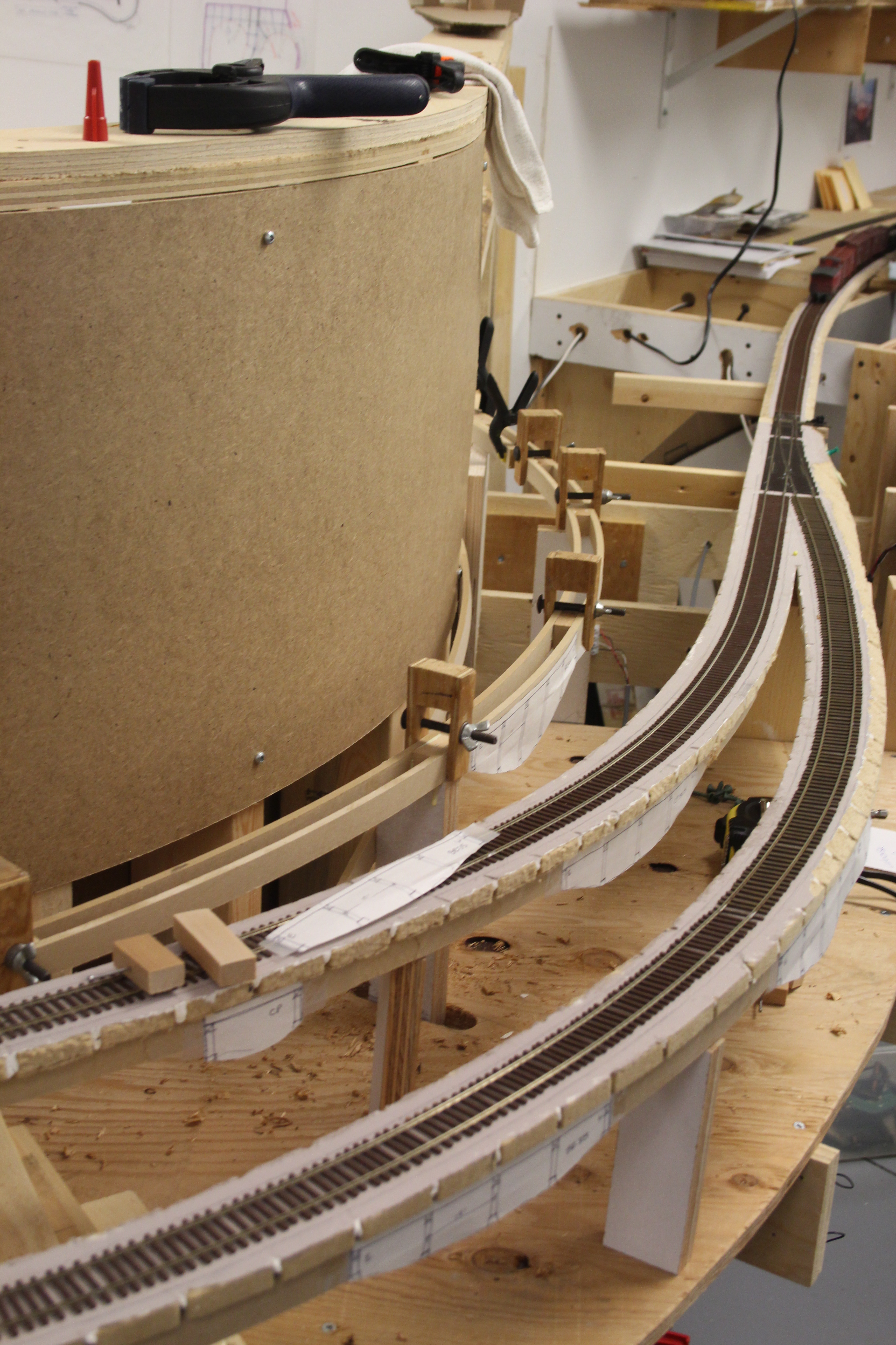

- April 12, 2015 | CPR Boundary Sub
test op session
.jpg)
In order to improve the chances of successful and enjoyable formal op sessions, we elected to convene two “test” op sessions during the months of March & April. These were relatively unstructured events that were intended to give the layout and equipment a shake out. Also – the crew too!
Trains were run in a sequential manner and everyone kept notes of suggestions, issues, challenges etc – which were all aimed at creating reliable equipment and fun op sessions. This proved to be a beneficial strategy and the valuable feedback that was received went into the planning of the timetable, paperwork and structure for the upcoming formal sessions as well as flushing out equipment or infrastructure that needed maintenance.
- March 7, 2015 | CPR Boundary Sub
room entry swing gate
Completion of the swing gate at the main entrance to the train room was completed and officially put into use today. One of the key learnings from the previous layout was to NOT install a “temporary” duck under at the room entrance on this new layout. The duckunder on the previous layout existed for well over 8 years.
.jpg) I did a lot of research into the methods for constructing various types of gates – there are so many! Because of the double deck geometry of the layout, we needed a swing gate since any vertical movement was not achievable. The gate was to swing into the room and span a double 48” wide door opening. I also wanted it to be out of the way when it was in the fully open position inside the room, so it was built to “nest” into the front of the layout next to the door opening so it would not protrude into the aisle. One other critical issue was that the track on the west end is on a 42” R curve that spans over the joint, and we wanted some ability to adjust the track alignment if things shifted at all.
I did a lot of research into the methods for constructing various types of gates – there are so many! Because of the double deck geometry of the layout, we needed a swing gate since any vertical movement was not achievable. The gate was to swing into the room and span a double 48” wide door opening. I also wanted it to be out of the way when it was in the fully open position inside the room, so it was built to “nest” into the front of the layout next to the door opening so it would not protrude into the aisle. One other critical issue was that the track on the west end is on a 42” R curve that spans over the joint, and we wanted some ability to adjust the track alignment if things shifted at all.
.jpg) A pretty tall order; however, Ken Catlin did a fabulous job of engineering the gate and associated works. He designed and built adjustable hardware for the free end based on some ideas I borrowed from David Doiron of Tempe, Arizona. He also soldered the rail continuously over sheet sections of circuit board on both ends of the gate and on the fixed parts of the railroad, and then cut the gaps in it to maintain accuracy in initial alignment.
A pretty tall order; however, Ken Catlin did a fabulous job of engineering the gate and associated works. He designed and built adjustable hardware for the free end based on some ideas I borrowed from David Doiron of Tempe, Arizona. He also soldered the rail continuously over sheet sections of circuit board on both ends of the gate and on the fixed parts of the railroad, and then cut the gaps in it to maintain accuracy in initial alignment.
The framing for both the gate and ends of the adjoining sections of the layout are heavily engineered and anchored to the walls – which are built of 2x6 studs with ½” plywood to provide earthquake strength for the house.
All framing on the gate was sealed with primer and then given a coat of paint to mitigate the risks of any shrinkage/expansion caused by our climate here on the west coast of Canada.
- February 25, 2015 | CPR Boundary Sub
mainline extended through nelson
.jpg)
The initial phases of track laying for the layout began at the east staging yard heading west, and at the temporary west staging yard heading in the opposite direction. Sounds like a lot of prototypes doesn’t it?! For some time, we effectively had 2 operational sections that weren’t connected due to the absence of the swing gate and no track through Nelson yard.
This yard is the main division point for the railroad, is over 35 feet long, contains numerous major structures, and is quite extensive, so we did not want to arbitrarily lay a track through it only to realign it later. Therefore, we did a full size mock-up of the entire yard trackage configuration on top of the plywood sub base. We then critiqued it and adjusted it several times, and once satisfied, took a series of overlapping photographs to record the “design” and noted the exact position of the mainline since most other yard tracks are parallel to it.
With that completed, we proceeded to add a few more feeders under the yard, then secured the plywood down, glued down the roadbed base layer, installed the raised cork roadbed along the mainline alignment, and painted it all a neutral beige color to blend it and seal it. Because there are several spurs coming off the main, just like the prototype, we needed to position those so turnouts could be installed as the mainline advanced through the yard. I didn’t want to cut the turnouts in later. The yard is curved in roughly the middle – again, just like the prototype.
Now that the mainline alignment is established and being laid, the next upcoming priority will be the swing gate at the entrance to the room.
- January 2015 | CPR Boundary Sub
car card pockets
With the commencement of operations in the not too distant future, I decided it was time to dig the millwork car card pockets that were used on the previous layout out of storage and repurpose them. Ken Catlin built most of them and did a beautiful job of them. I ordered new lettering graphics from my son in Australia and re-lettered most of them.
Here is a photo of the group of most of them, and of one installed on the layout.
.jpg)
.jpg)
- November 2014 | CPR Boundary Sub
installation of fascias
Nothing make a layout look neater than the installation of front fascia panels, so I decided to keep installing these as construction proceeded along the mainline. We use plywood risers to support 1/8” thick hardboard which is painted a charcoal black color.
I really like the contemporary, almost theatrical look of the darker color. We use commercial plastic molding strips to connect the sheets together and a J strip along the bottom edge to achieve a neat and crisp look. The bottom strip also provides that edge with a bit more rigidity.
Here is a series of example progress shots of the installation where the long Kootenay River Bridge will go.
.jpg)
.jpg)
.jpg)
.jpg)
- October 25, 2014 | CPR Boundary Sub
Installing cvp wireless system
We used a Lenz system on the previous layout, and after further research and reflection, we elected to keep it for the new layout, but supplement it with the Lenz compatible wireless system by CVP. We want the freedom particularly for the crews operating trains on the very long isolated mainline sections of the layout. One receiver gives us capability to run 8 wireless throttles in conjunction with the Lenz tethered throttles.
The installation was relatively easy and we are using both the new generation T5000, and a couple of older generation T9000 throttles. There is great freedom for the engineers with wireless throttles while they are operating.
.jpg)
.jpg)
- September 2014 | CPR Boundary Sub
temporary west staging yard completed
Because a primary goal was to reach an operable stage as early as possible with this large layout, we elected to moderate the efforts by building the first phase from the east staging yard to a temporary west staging yard just beyond Castlegar. This would yield a mainline length of 175 feet initially out of the eventual 500 foot mainline. Coincidently, this is almost the same length as the entire complete mainline on the previous layout.
.jpg) This objective necessitated the construction of a temporary staging yard that could be relocated in the future as the mainline advanced around the room. This yard has 4 tracks (which upon hindsight should have been 5!) and is built on a 12 foot long module that is cantilevered from the walls.
This objective necessitated the construction of a temporary staging yard that could be relocated in the future as the mainline advanced around the room. This yard has 4 tracks (which upon hindsight should have been 5!) and is built on a 12 foot long module that is cantilevered from the walls.
- April 2014 | CPR Boundary Sub
Completion of the kfp mill site track
Kootenay Forest Products (KFP) was owned by the Eddy Match Co. and had a sizable mill operation that operated for many decades at a location east of the Nelson divisional yard. Even though this facility occupies a large corner on the layout, we have condensed this operation substantially while attempting to capture the general unique aspects and feel of it. For example, the CPR mainline actually ran through the middle of the mill, so there are spur tracks on both sides of the main.
We are building mock up buildings from foamcore materials for now until the overall massing is determined and purposes for some of the prototype buildings.
.jpg)
.jpg)
- October 2013 | CPR Boundary Sub
first train arrives at proctor / east staging yard
.jpg)
The east end of the modelled layout terminates at Proctor which is 20 miles east of Nelson. Because I prefer open and accessible staging yards, I opted to model this yard after the prototype yard located at Proctor, BC with additional supplemental staging tracks to increase the capacity. This decision also created an opportunity to include the interesting 3 track rail transfer barge slip located there as another interchange location.
The yard, when completed, will include the station and several other railroad buildings as well as the actual barge slip, 3 track barge, and associated waterfront. Here is engineer Sylvan running the first train into the yard.
- September 2012 | CPR Boundary Sub
spline system begins
Everywhere on the layout where the track is not on a “table top” plywood type area, a 3 spline system with spacer blocks is utilized to support the roadbed. This work progresses around the layout with the use of numerous tools and techniques at a rapid and accurate pace. Spline systems offer naturally occurring vertical and horizontal transitions and are very easy to super-elevate without a lot of complicated calculations and shimming.
We also found they are easy to modify when things need to be changed!
.jpg)
.jpg)
- August 2012 & Ongoing | CPR Boundary Sub
wiring, wiring and more wiring
Even with DCC, a layout of this size requires a lot of wiring. Much of the layout is open module or cantilevered joist framing as noted previously, however, the large yard areas are solid plywood tops. So, who wants to crawl under the layout to install bus wires & feeders – not us! So, we guesstimated the number of feeders we would need along these major yard areas, added more as a contingency, and ran the bus wires and installed these feeders before the plywood tops were installed. That was definitely a back saver! Once the track is down, we only need to feed the wires up through the plywood at the correct locations.
.jpg)
.jpg)
- Spring/Summer 2012 | CPR Boundary Sub
let the framing begin
.jpg)
The layout design required a lot of complicated wall framing to support all the cantilevered benchwork for the narrower sections of the layout. I opted to build a lot of the layout at 10” to 14” widths to maximize the mainline run per square foot of scenery. As a result, significant lengths of these narrow shelves are cantilevered off the walls with no other support. This provides for a cleaner look and more generous aisles.
.jpg) To achieve this design goal, construction of 2 complicated curved walls within the room was required. One is a 5ft high double curved stub wall shaped almost like an inverted question mark, and the other a full height tear drop shaped peninsula. They are made from 2x4 studs and double ¾” laminated curved top and bottom plates which are expansion bolted to the concrete floor. The plywood layout joists are screwed to the wall studs and cantilevered. The construction of this framing and the associated layout framing spanned over many months. There are no nails used in the framing – everything was screwed together with that awesome Canadian invention; the Robertson screw!!
To achieve this design goal, construction of 2 complicated curved walls within the room was required. One is a 5ft high double curved stub wall shaped almost like an inverted question mark, and the other a full height tear drop shaped peninsula. They are made from 2x4 studs and double ¾” laminated curved top and bottom plates which are expansion bolted to the concrete floor. The plywood layout joists are screwed to the wall studs and cantilevered. The construction of this framing and the associated layout framing spanned over many months. There are no nails used in the framing – everything was screwed together with that awesome Canadian invention; the Robertson screw!!
- Spring/Summer 2012 | CPR Boundary Sub
module construction commences
A substantial length of both decks of the layout abuts the perimeter walls in the train room, therefore, again we opted to cantilever as much of the benchwork as possible off the walls. We are prefabricating modules from ¾” plywood cut into 3 ½” widths (to match dimensional 1x4 lumber). These were then predrilled for wiring and pre-assembled in the required lengths using 4 feet as a standard where possible.
Doing most of this work in the shop kept all the messy sawdust work out of the train room. These modules were then simply leveled, attached to their adjoining mates, and secured to the walls with long reach wood screws into every stud. Here are a few shots that show some of this work.
.jpg)
.jpg)
- March 2012 | CPR Boundary Sub
Into the new house.
.jpg)
We moved into our new home in the spring of 2012, and because the train room was the largest “empty” space in the house, it quickly became a storage and staging locker! It looked like this for quite a while.
.jpg)