-
layout photographs
One of the main objectives for this layout was to achieve and maintain an operations capable layout during its construction, which means that the construction is continuously progressing in phases.
Each project is focused on accomplishing a specific objective towards improving or expanding the ability to operate the layout. Typically, most major phases are motivated by an upcoming operations event such as VanRail or RMMBC.
The posts below are a sample of various stages in the work, so check back often as we continue to update this section.
-
February 2024; Layout Progress Photos
-
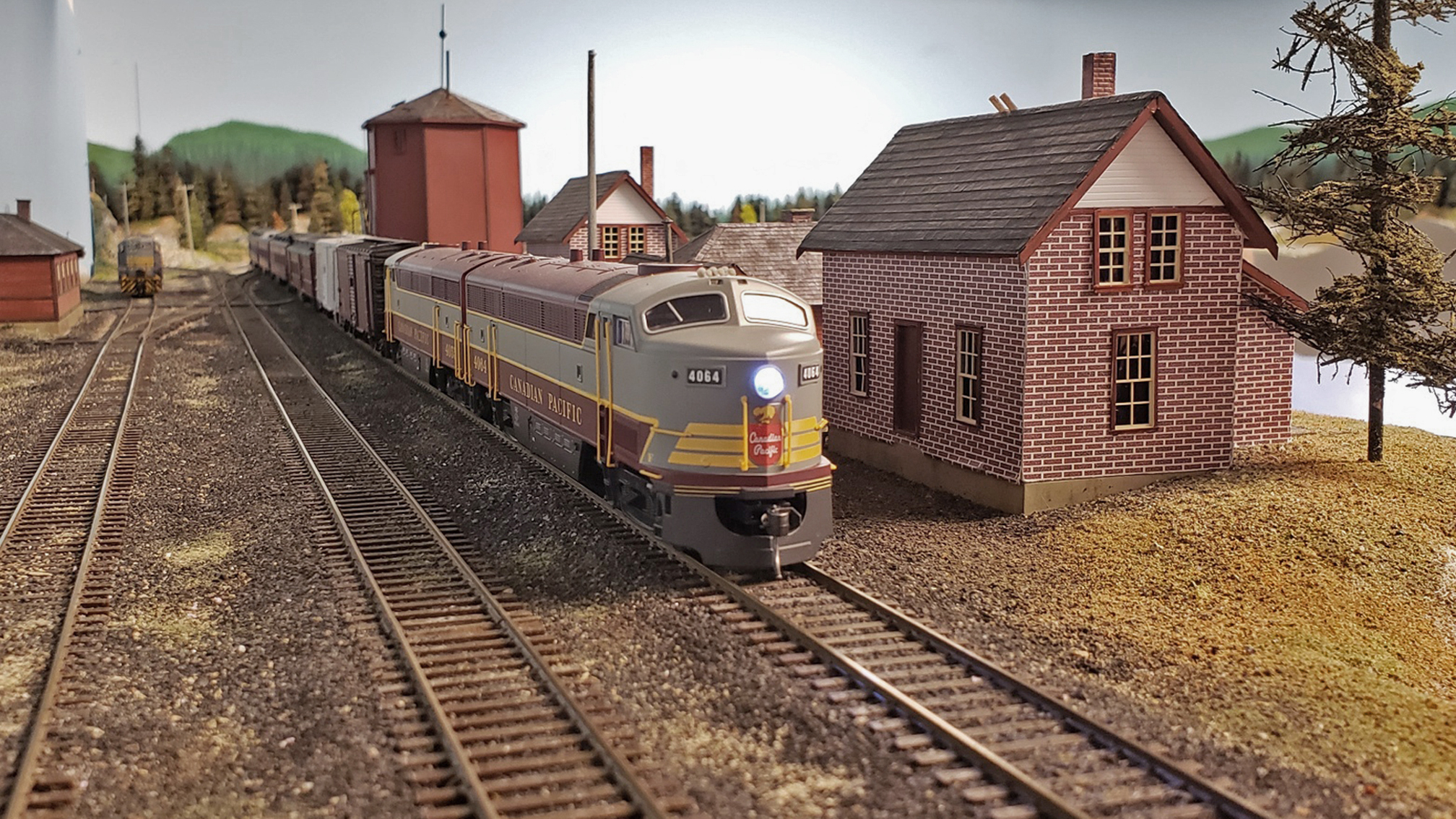
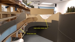
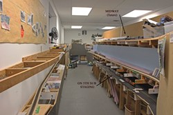
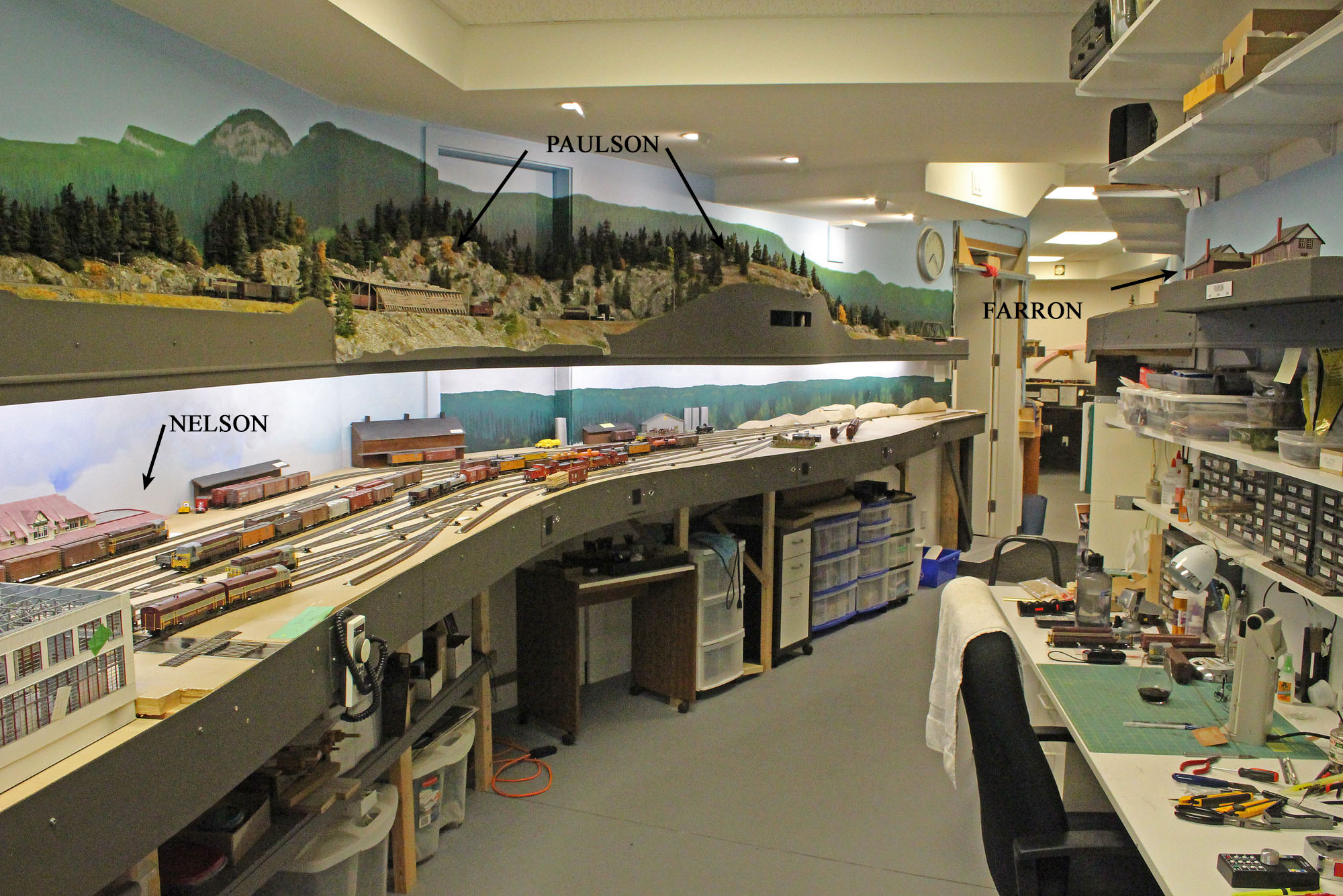
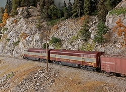
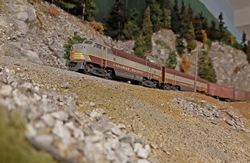
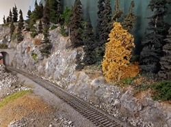
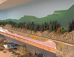
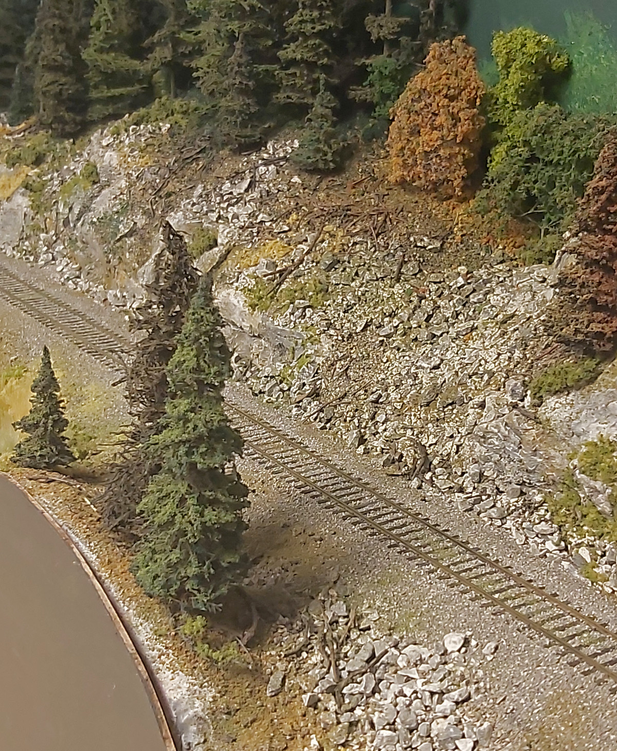
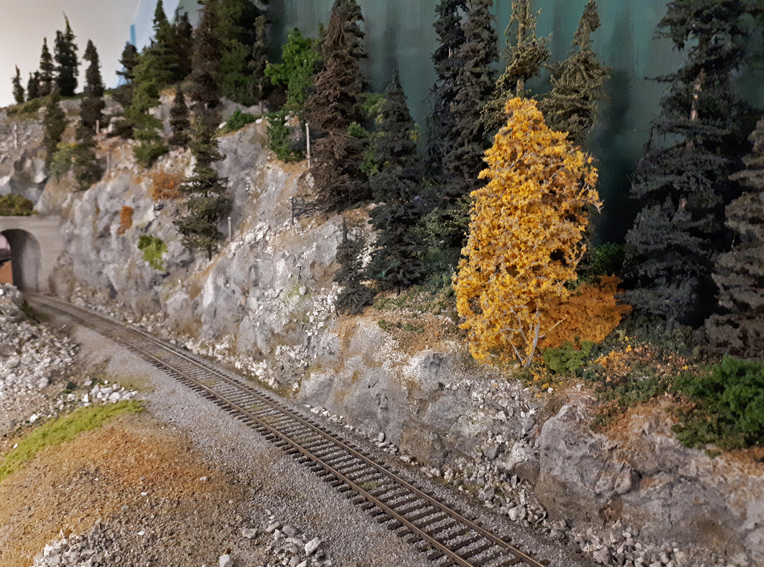
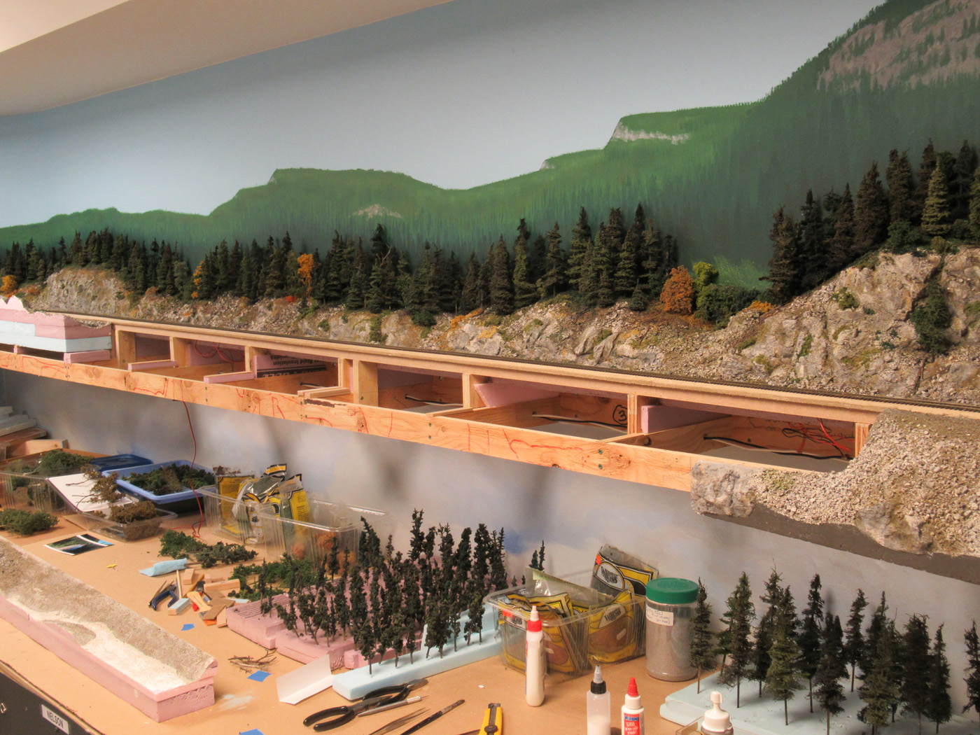
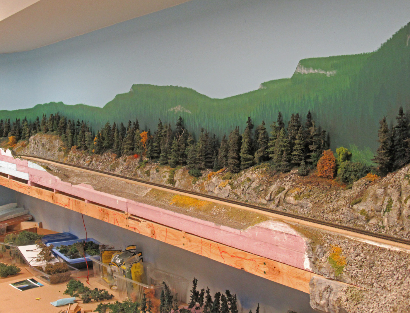
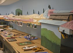
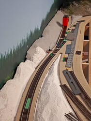
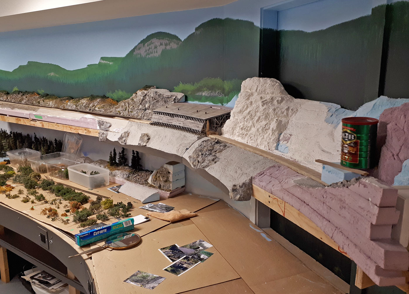
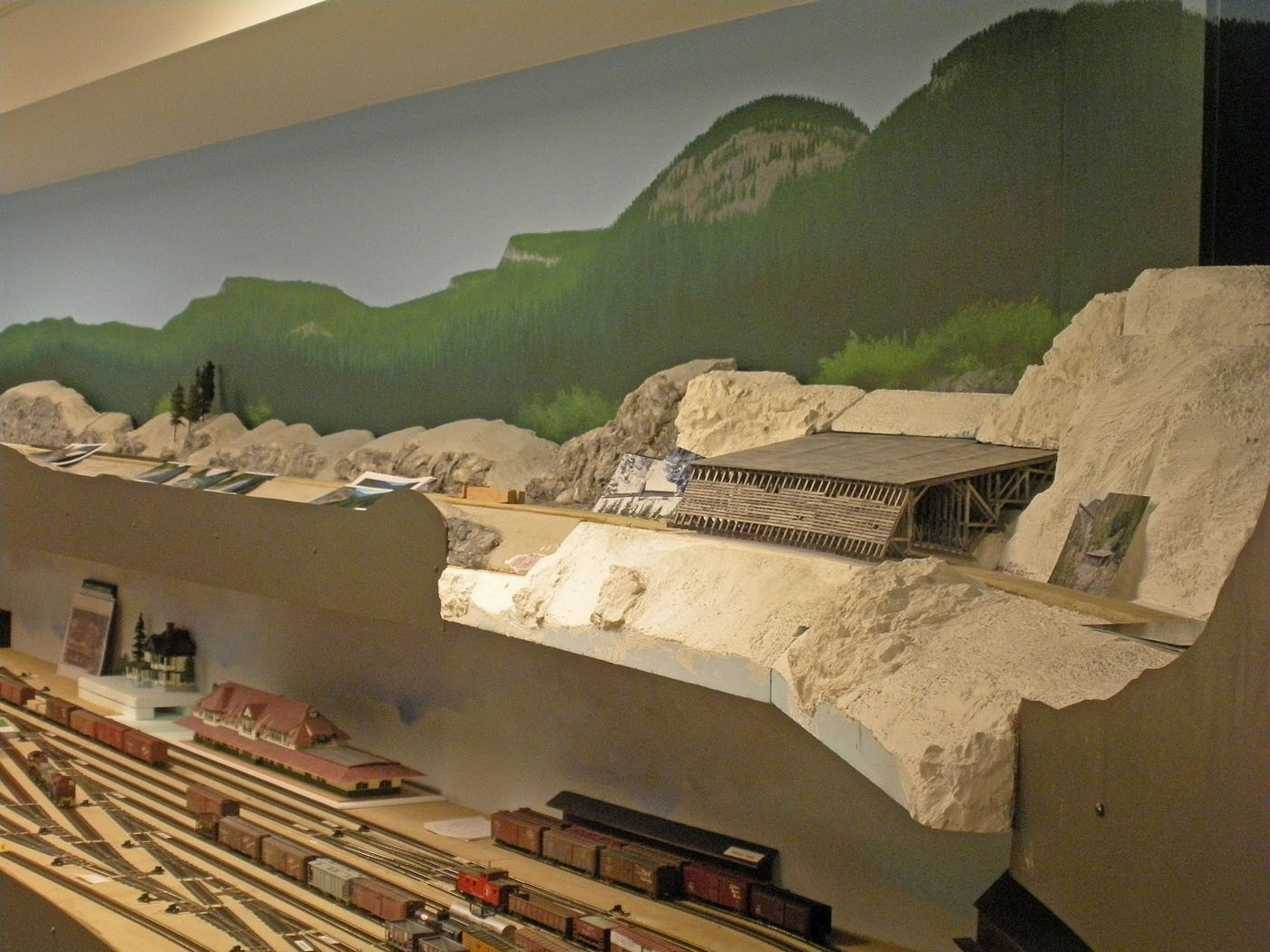
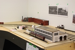
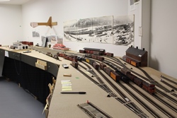
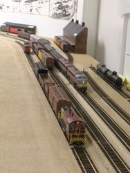
Below are a few photographs of the sceniced upper deck of the layout including Farron and the Paulson area near the summit of this section of the Boundary Sub.


-
February 2023; Layout Progress Photos
-
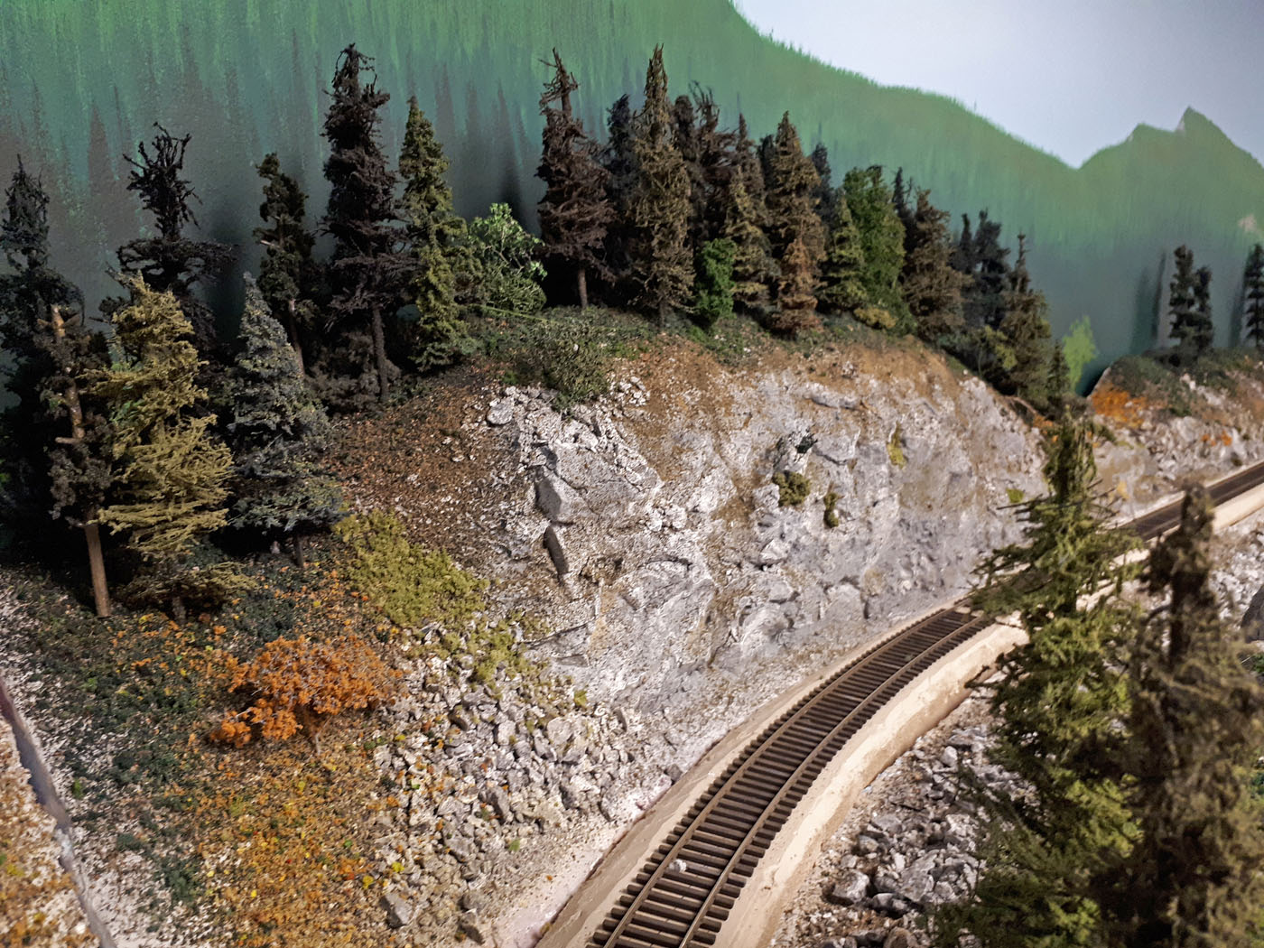
Below are some recent photographs of the relatively completed areas of the layout along the upper shelf above Nelson.
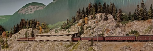
Photo taken by Margot Calvert.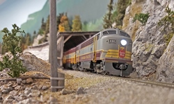

-
Below are some recent photographs along the Farron upper deck shelf. While there is still some work required to complete the scenery in Farron, however, I am quite happy with how things look so far.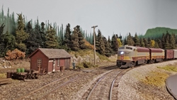


-
June 2021; Layout Aisle Photos
-
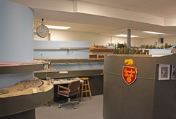
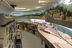
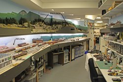
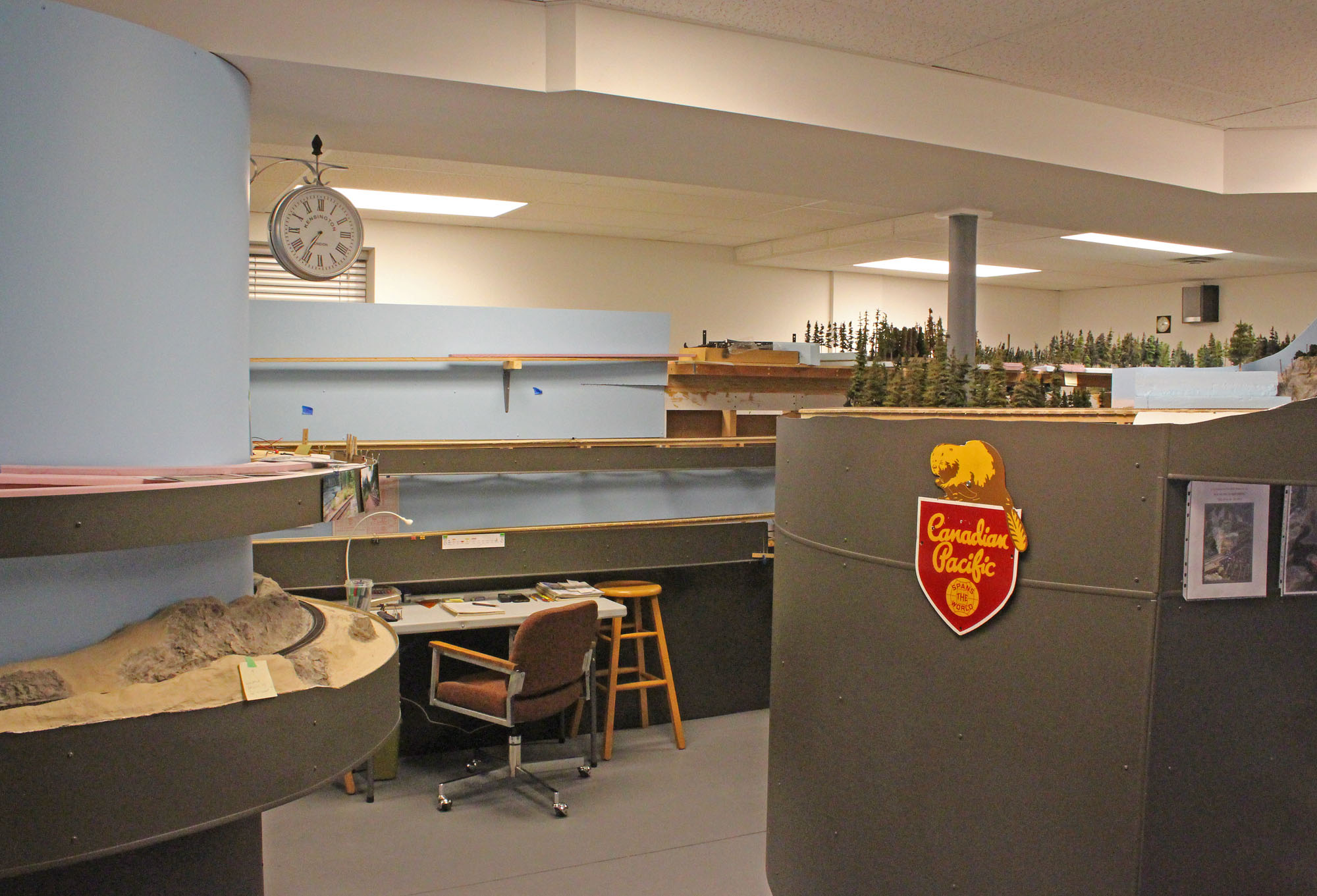
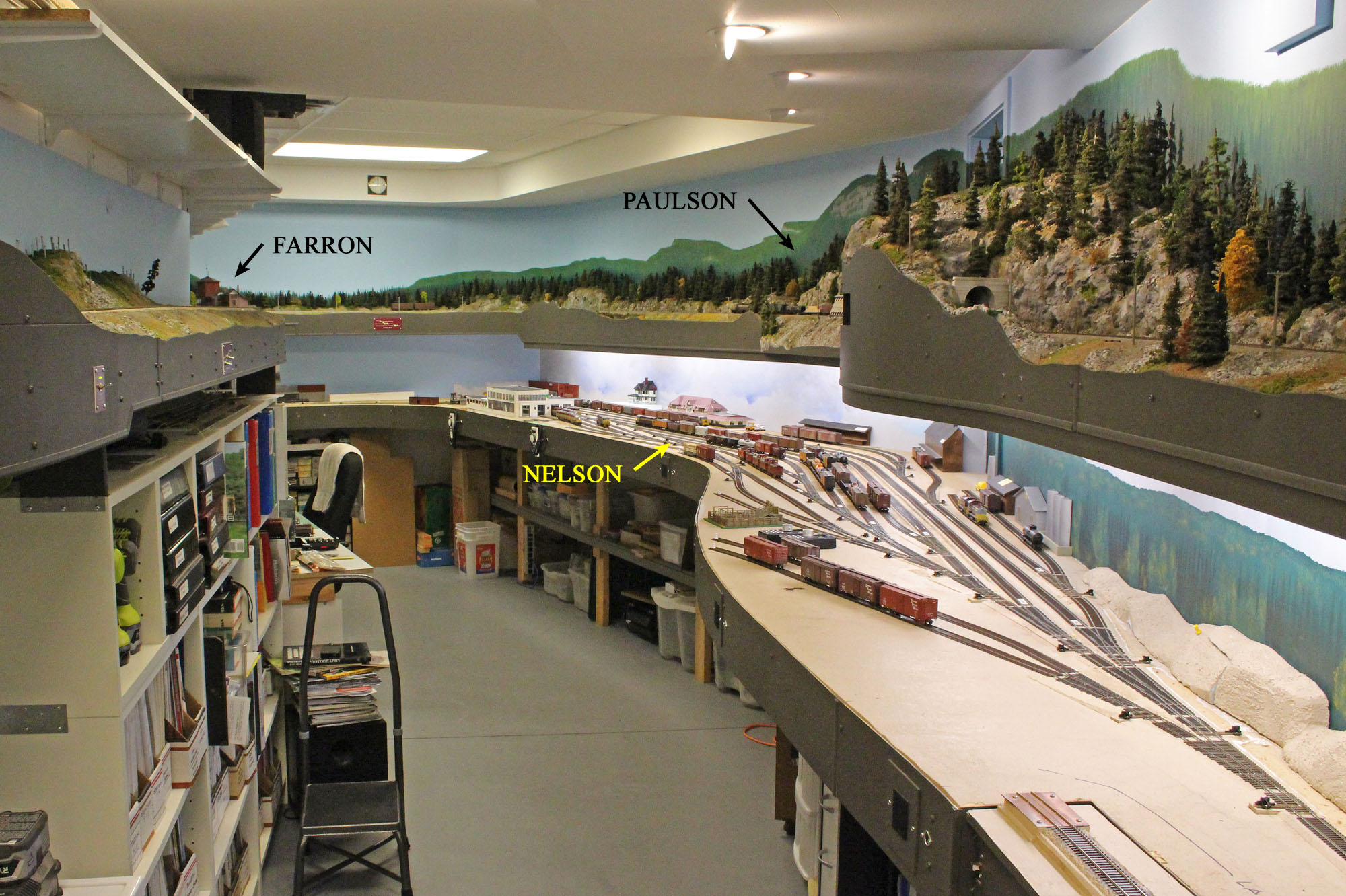
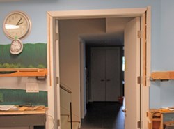
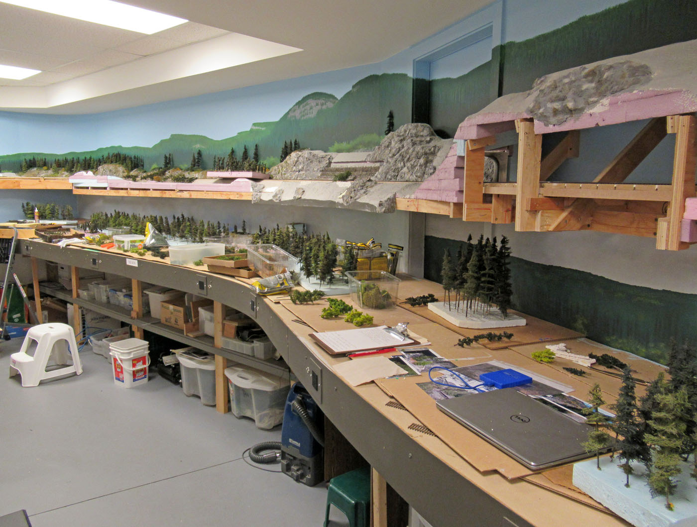
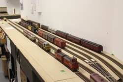
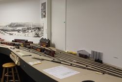
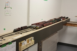
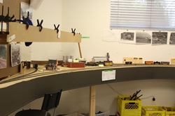
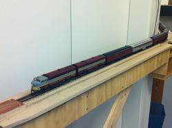
In June 2021 I prepared these overall layout photos to be included in the Virtual layout Tour video I did for the 4th Division, PNR, NMRA. They are intended to provide a overview of the layout from the various aisles.


-
Summer 2020; Upper Deck Progress Photos
-
Here are a few recent photographs along the (almost) completed upper deck over Nelson.


-
Fall 2019 & Spring 2020; Upper Deck SCenery
-
The last update on this project was in Summer 2019 below, and since then we have tackled a lot of progressive finishing steps towards completion of finished scenes. While there are always various small items to attend to, we are getting “close enough”, so offer the following.
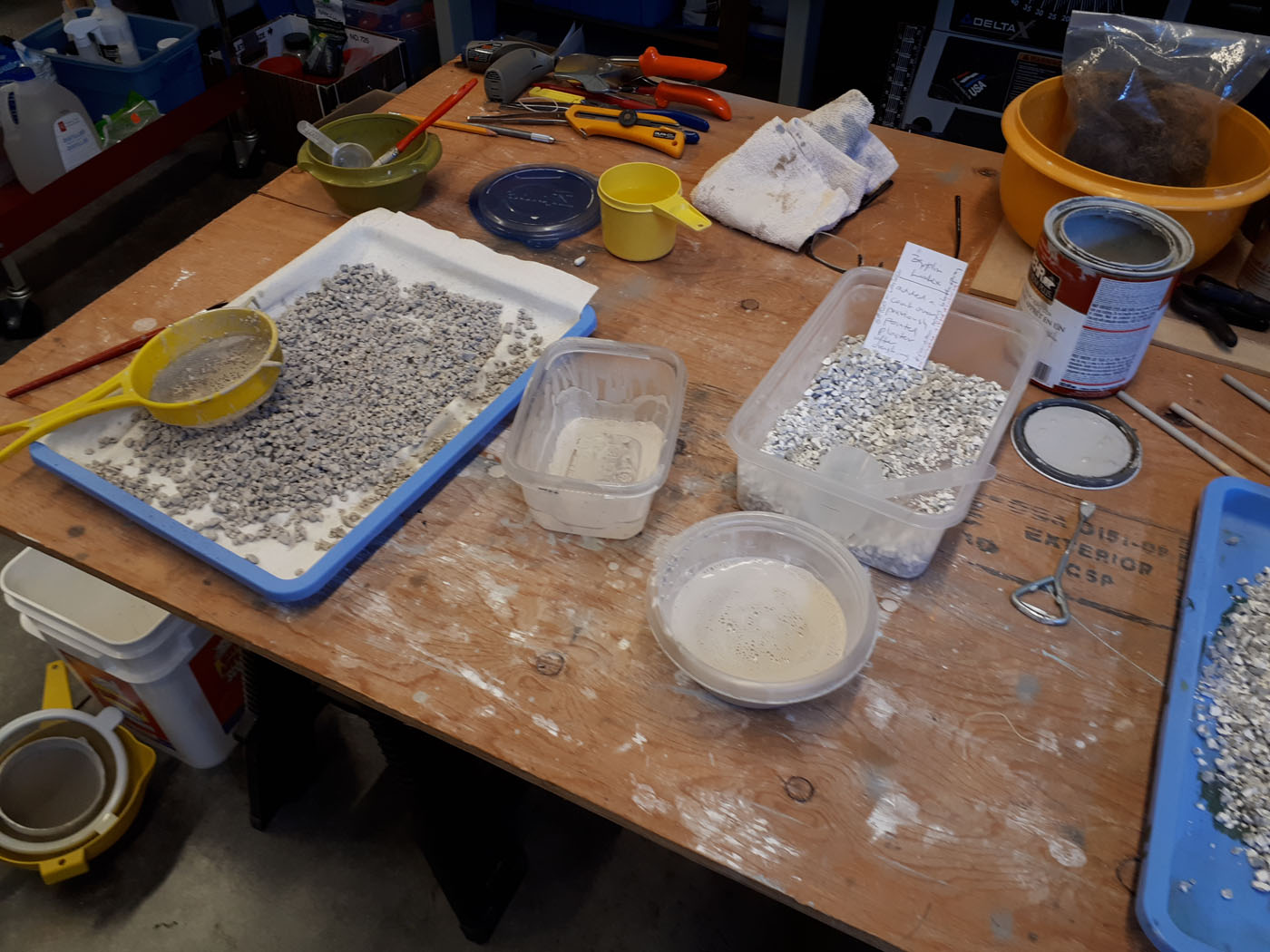
We needed a LOT of rock talus for the layout and I wanted it to blend with the colors of the rock castings, so we undertook making our own talus from scrap plaster castings. They were crushed, sifted and sorted into sizes. They were colored by immersing in a thin mix of the various latex paint colors than were used on the rock castings and then spread out on heavy duty paper towels to dry. We usually left them for several days to ensure they were completely dry before using the materials.
-
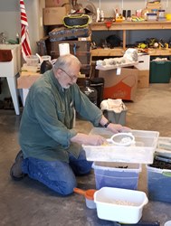
The plaster was crushed by wrapping it in a cloth and bashing it with a hammer and an old rolling pin. Then it was sifted to remove all the powder and dust from the mix as seen in this photo.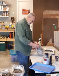
Numerous color batches were created by soaking the talus in a thin mix of various latex paint colors.

Here we can see some freshly colored talus spread out on plastic trays covered with commercial grade paper towels. Several times during the drying process, the talus would be moved around to loosen it from the paper towel and to expedite the drying.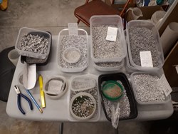
The different colors and sizes were sorted into cheap plastic containers and labelled for use. This photo only shows some of the talus we created.


-
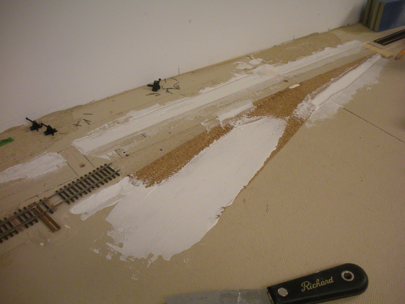
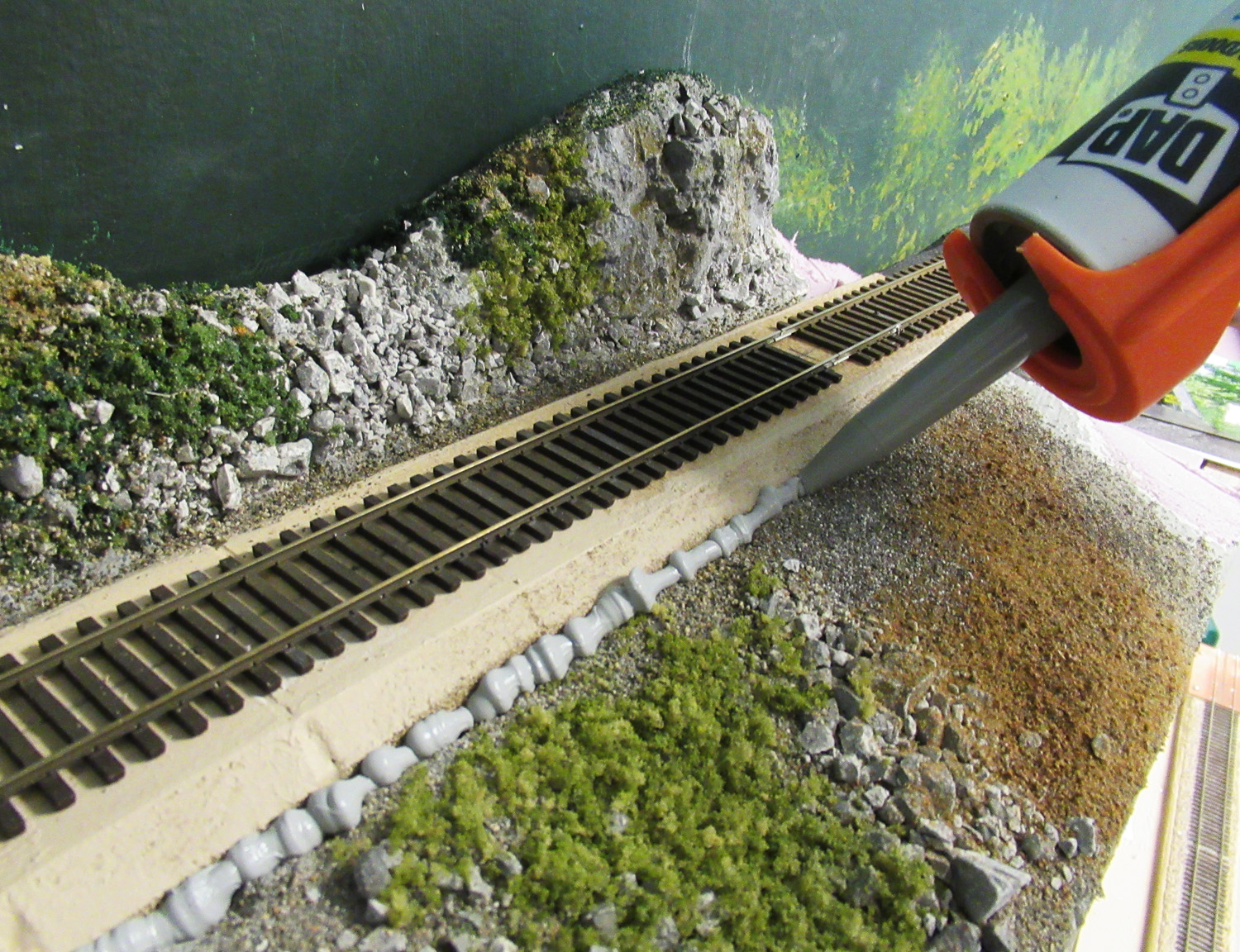
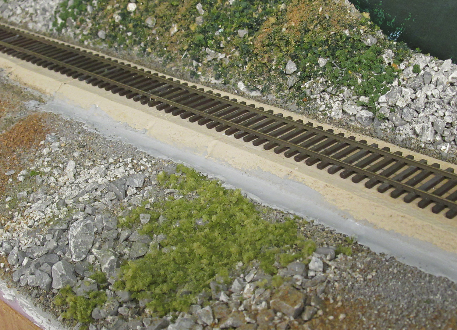
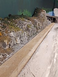
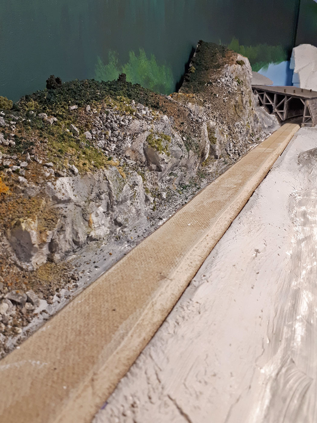
A custom mix of several colors of Woodland Scenics fine ballast was created to blend with the colors of the rockwork and talus in the area. Once the previously sceniced landforms were glued in place, the gap between them and the roadbed was sealed using a DAP grey coloured caulk. The caulk was smoothed out and some sand was pushed into it before it dried. This gives the subsequent ballasting something to bind to. Then the adjacent scenery textures and colors were extended and blended into the ballast.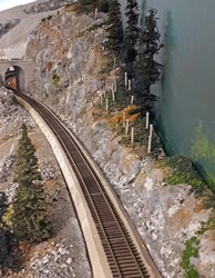
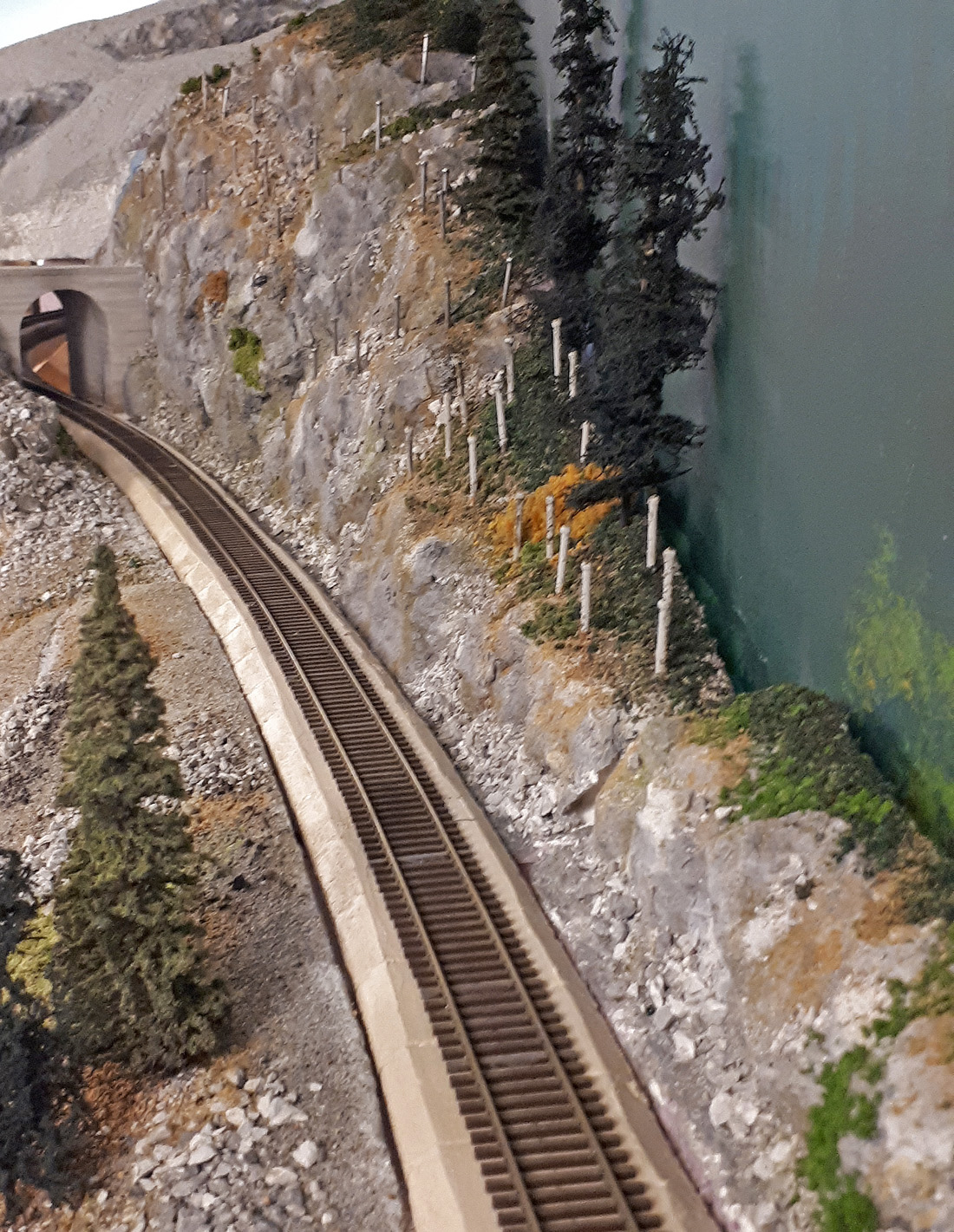
The adjacent landforms have been glued in place on either side of the mainline west of the Paulson tunnel. The gaps between the roadbed and landforms can be clearly seen and it is essential to seal these – unless you want to ballast the deck below this one too!
The DAP caulking is applied in sections along both sides of the roadbed.

It is smoothed out with your finger to blend in with the adjacent landforms.
Gaps between adjoining landforms are also caulked in the same manner.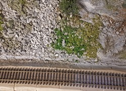
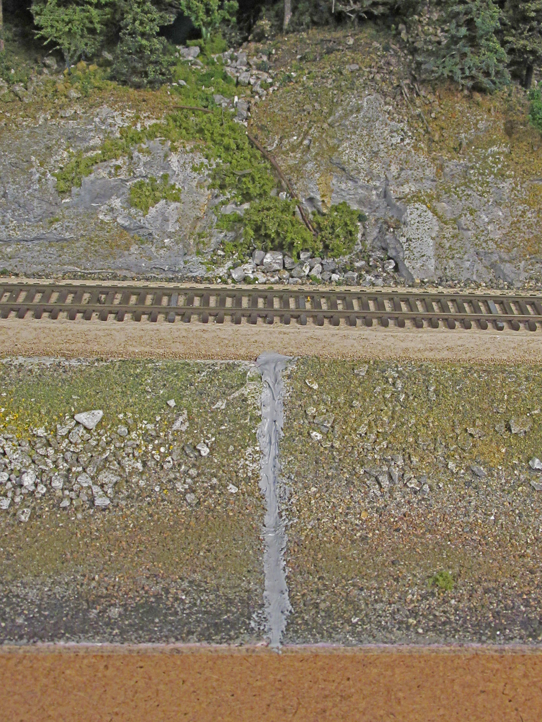
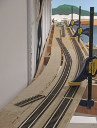
Play sand is pushed into the wet caulking as can be seen on the left side in this photo.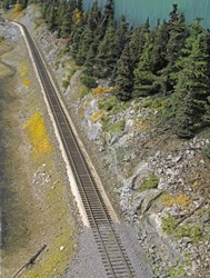
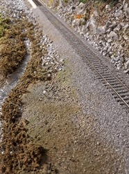
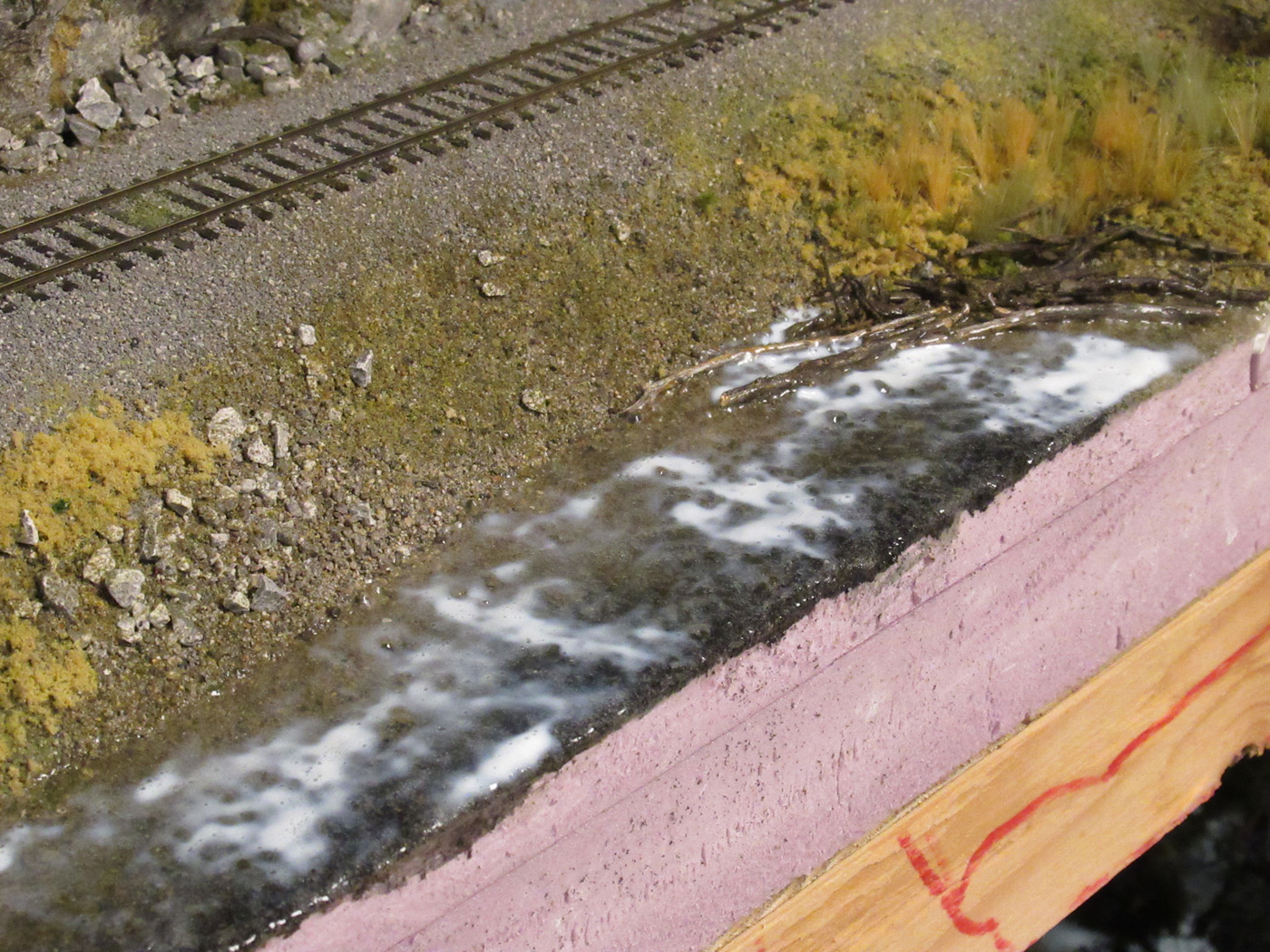
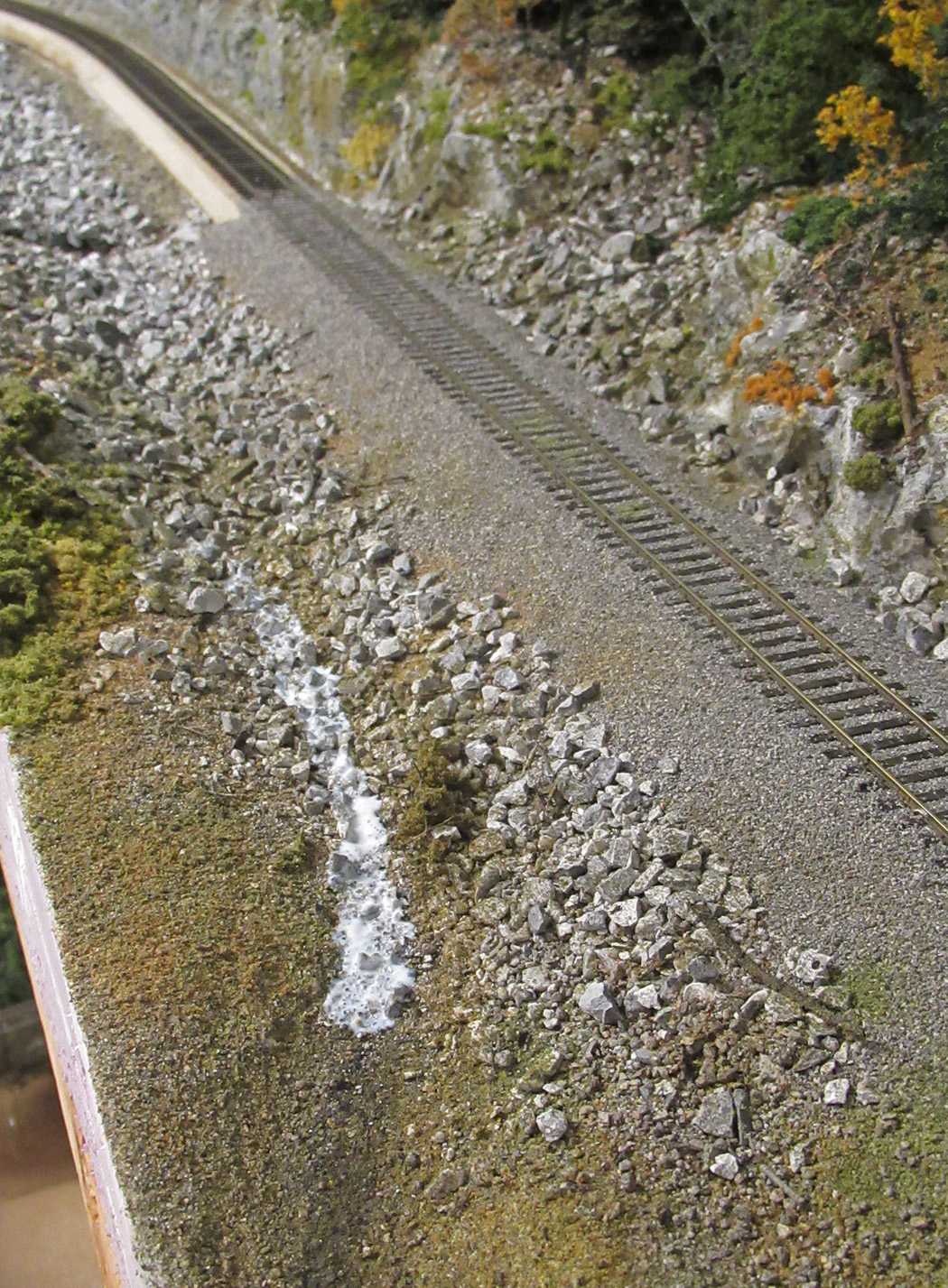
This view along McRae Creek shows the transition between completed ballast work and the caulking with play sand in it.
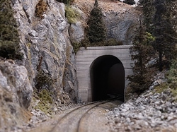
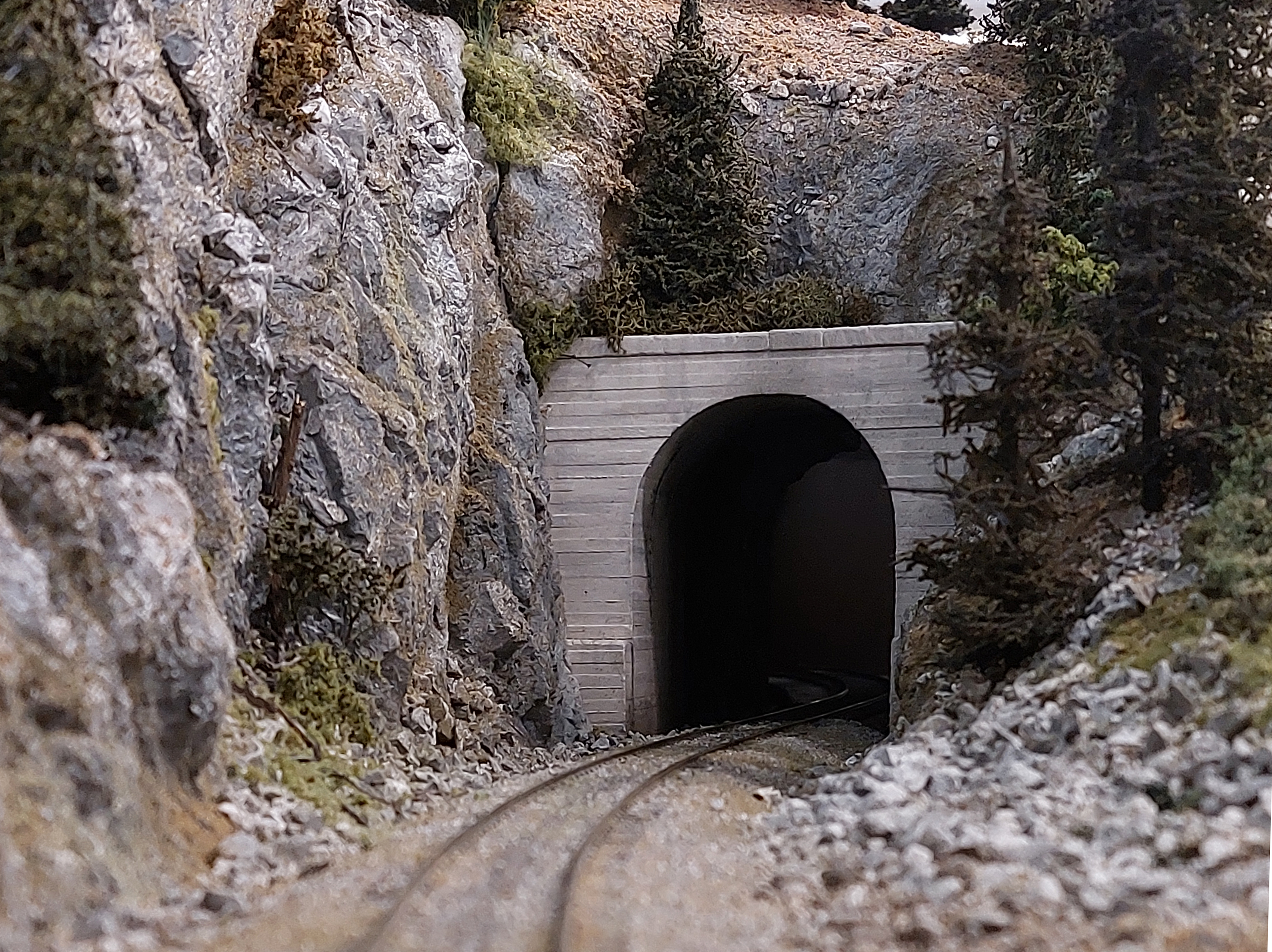
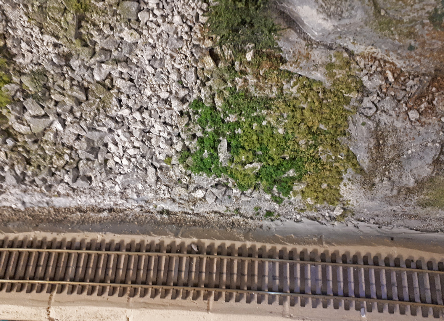
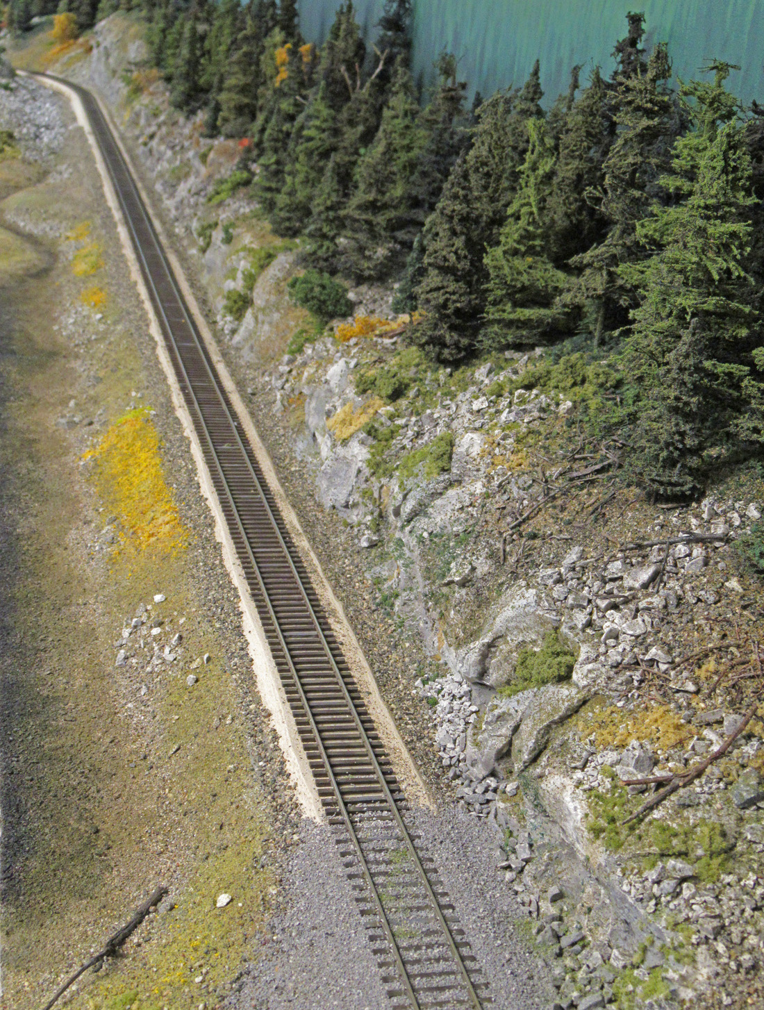
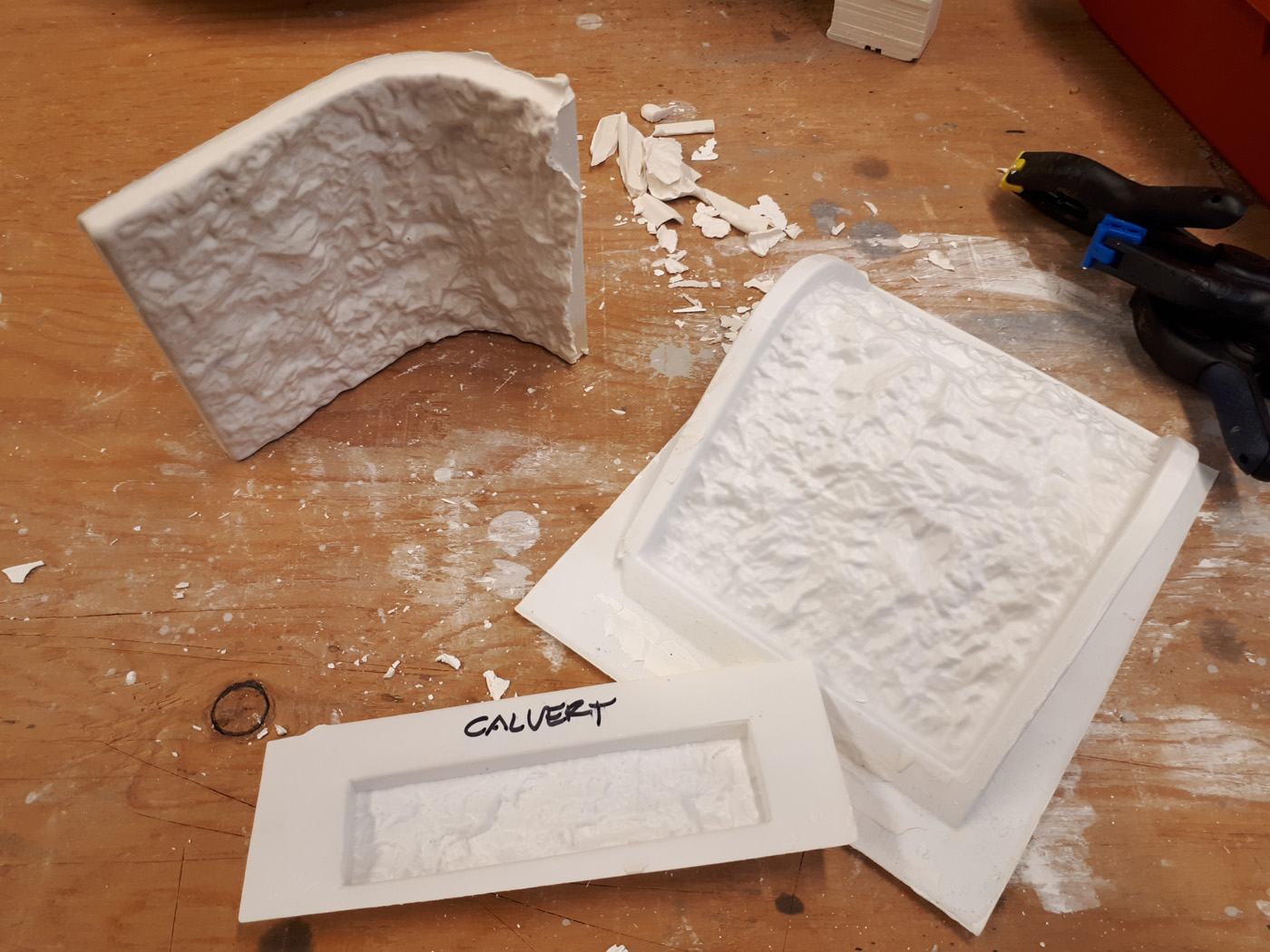
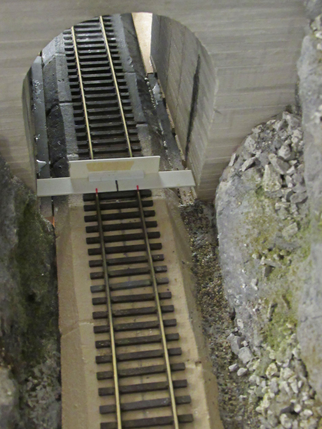
These three photos show sections of the completed ballasting. One of these photos also has a joint between adjoining landforms; however, it cannot be seen anymore. Integrating the cast portals and liners for the Paulson tunnel was a tricky project, particularly because we wanted to replicate the look of the prototype ones as closely as practical. As reported in the June 2019 What’s New post, these concrete portals and associated liners were all cast using a custom fabricated mold.
Because there are sight lines into the tunnel, we also made several rock liners using the Woodland Scenics plastic mold. These were sanded and then glued together using carpenters glue. We then strengthened the assembly with plaster gauze laid over them. The rock liners were given a spray of flat black paint to create a visual depth to the tunnel.
Positioning the portal assemblies and fitting them into the plastered landforms took a fair bit of effort, however, the results are quite satisfying.
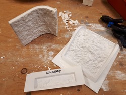
Tere we see the Woodland Scenics plastic tunnel liner rock mold, and one of the castings.
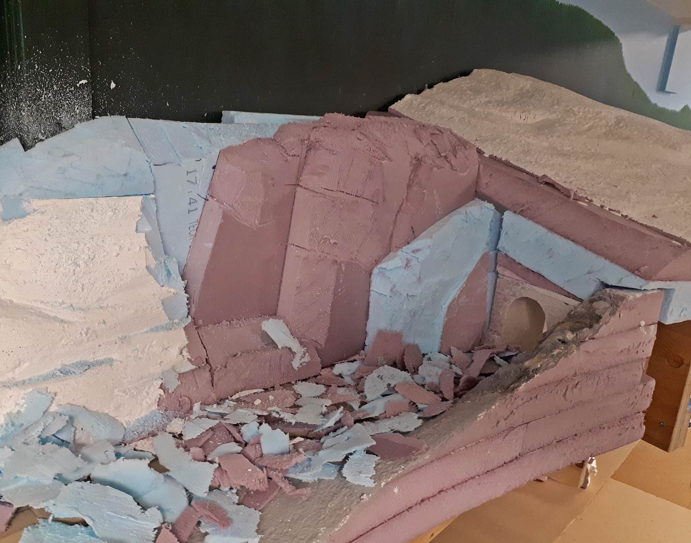
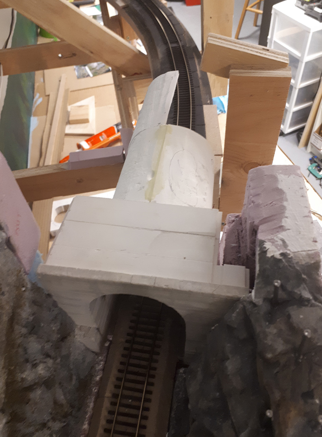
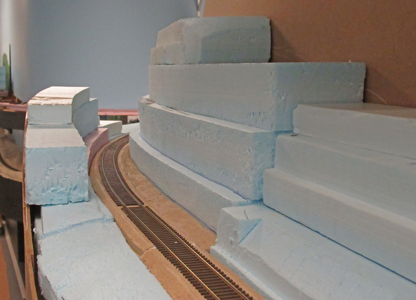
The east portal is loosely in position and the Styrofoam landform is being carved in place to create a good fit.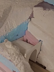
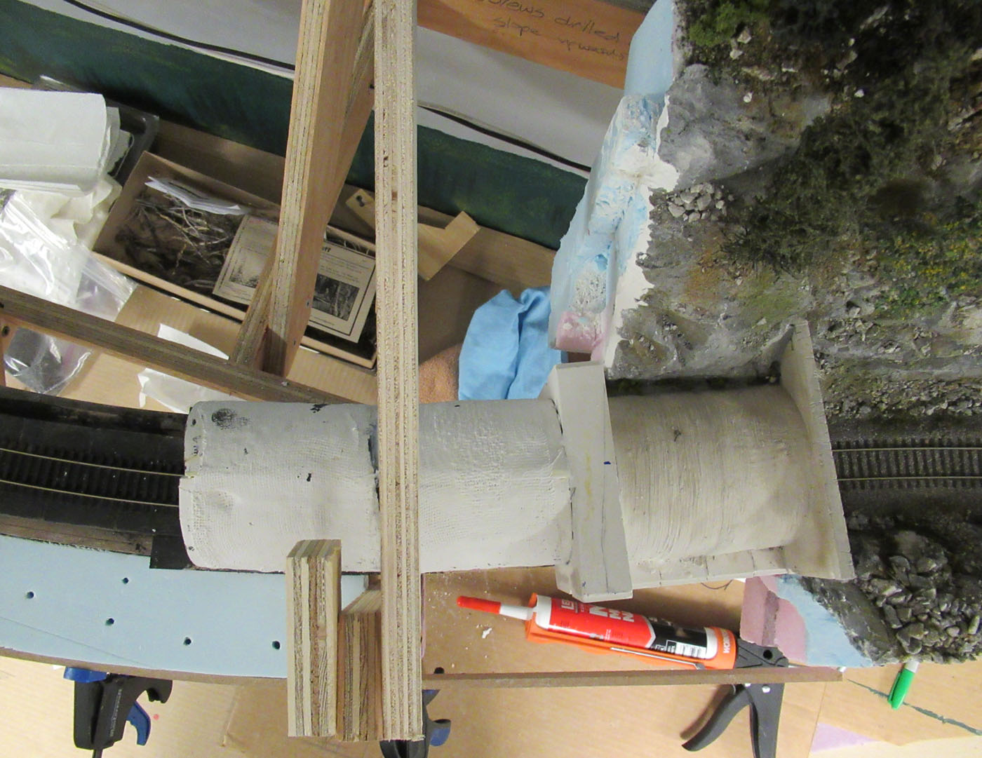
The west portal has an exposed concrete liner right behind it, so this assembly had to be notched into the landforms.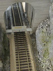
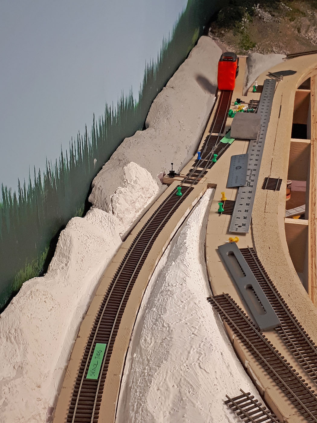
This is a styrene spacer tool to ensure the portals are centered on the track alignment as they are being fitted into the scenery.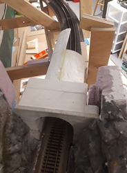
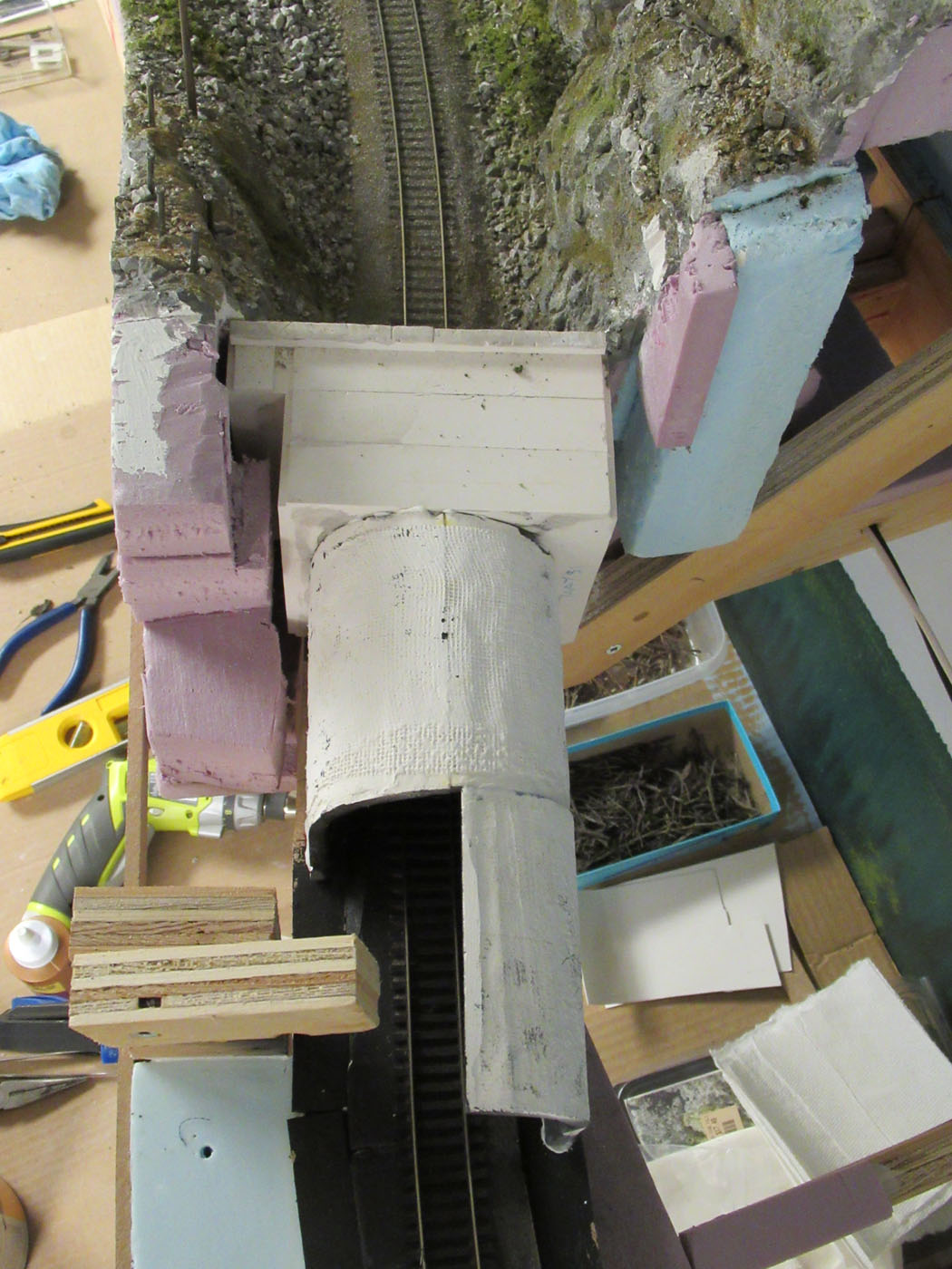
A views of the east portal assembly being fitted against the sceniced landforms.
A views of the east portal assembly being fitted against the sceniced landforms.
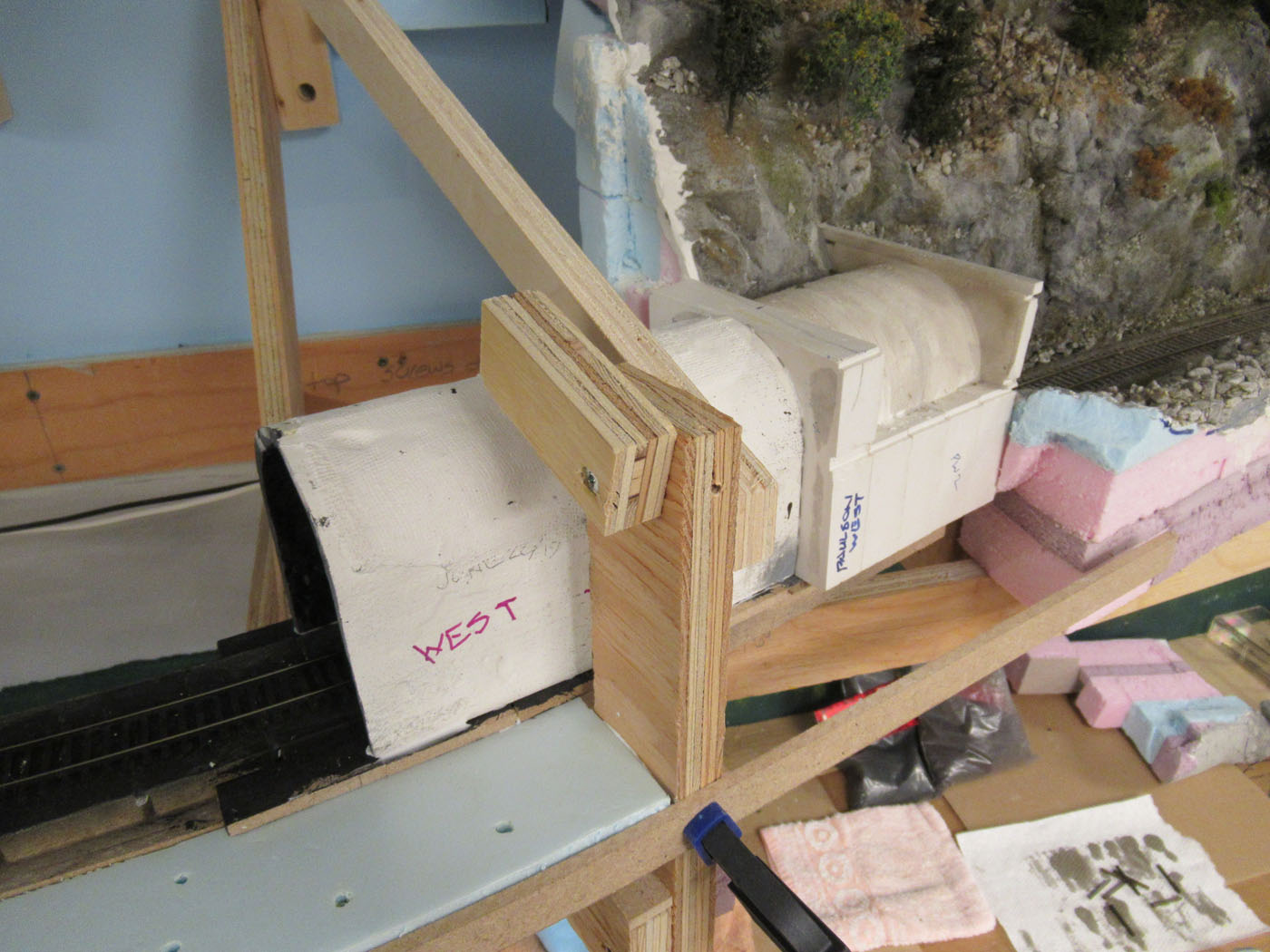
A views of the west portal assembly being fitted against the sceniced landforms.
A views of the west portal assembly being fitted against the sceniced landforms.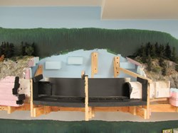
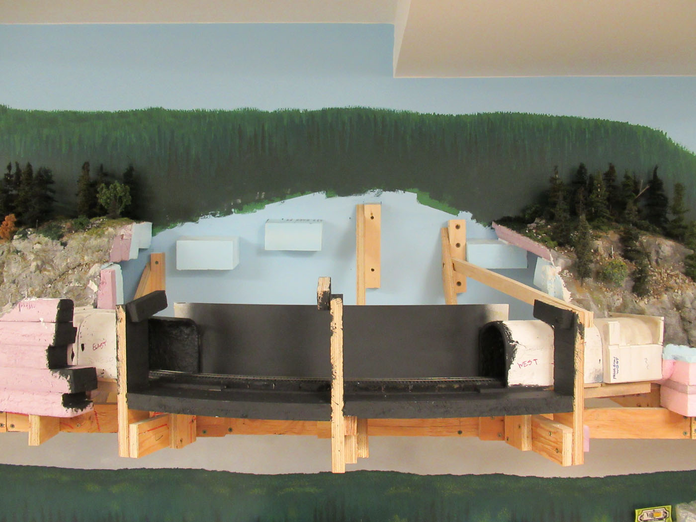
A side view of the tunnel location with the portal assemblies in place.
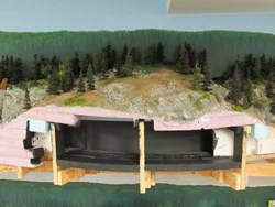
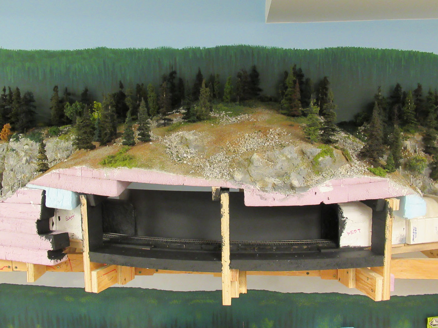
The same view as the previous one – except we have now placed the sceniced landform “lid” on top of the tunnel area.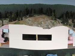
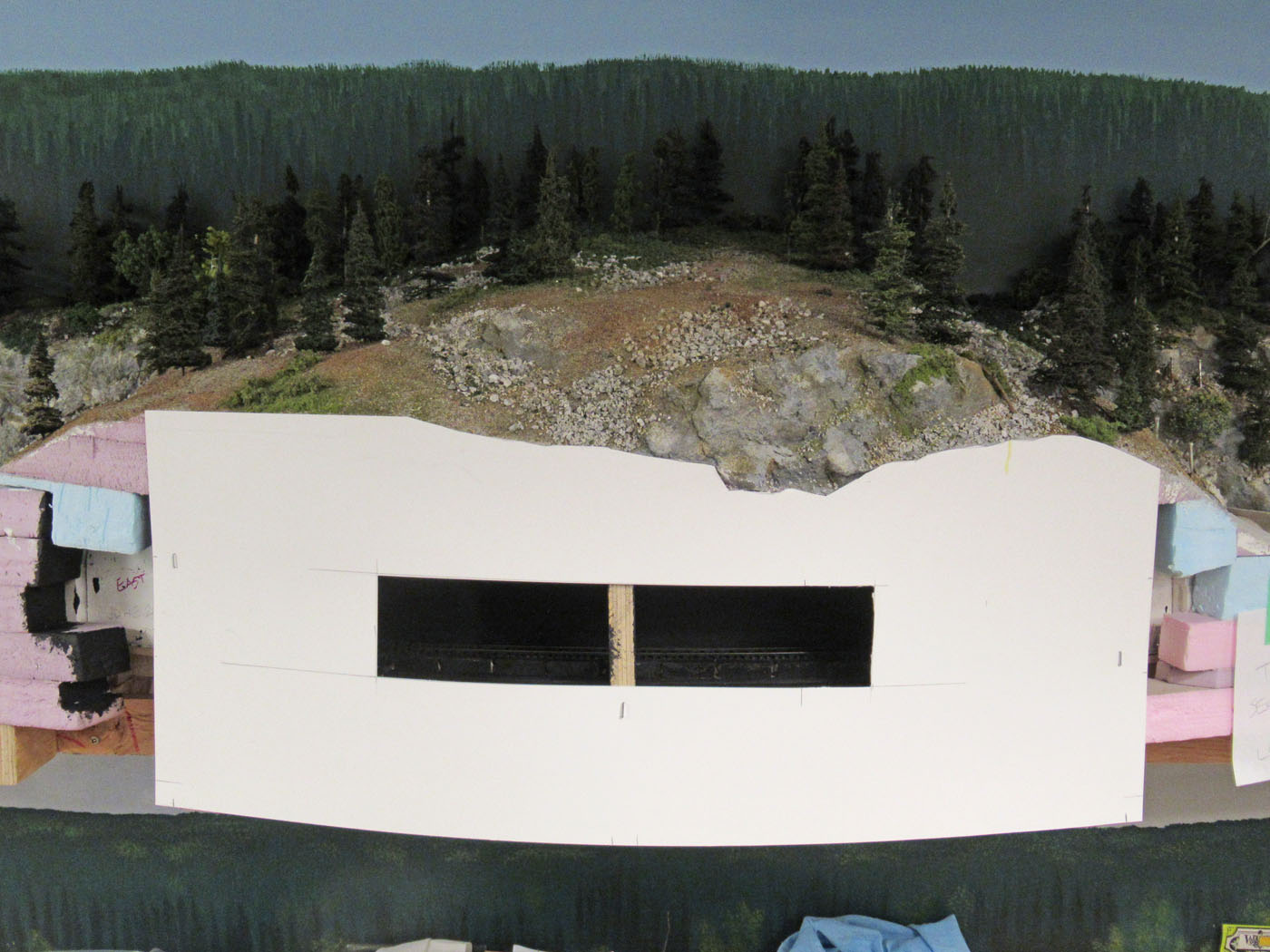
The same view as the two previous ones with a cardboard fascia template installed over the tunnel area. This helped determine how to ensure there would be sufficient permanent access to the tunnel once completed. 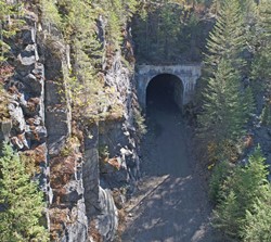
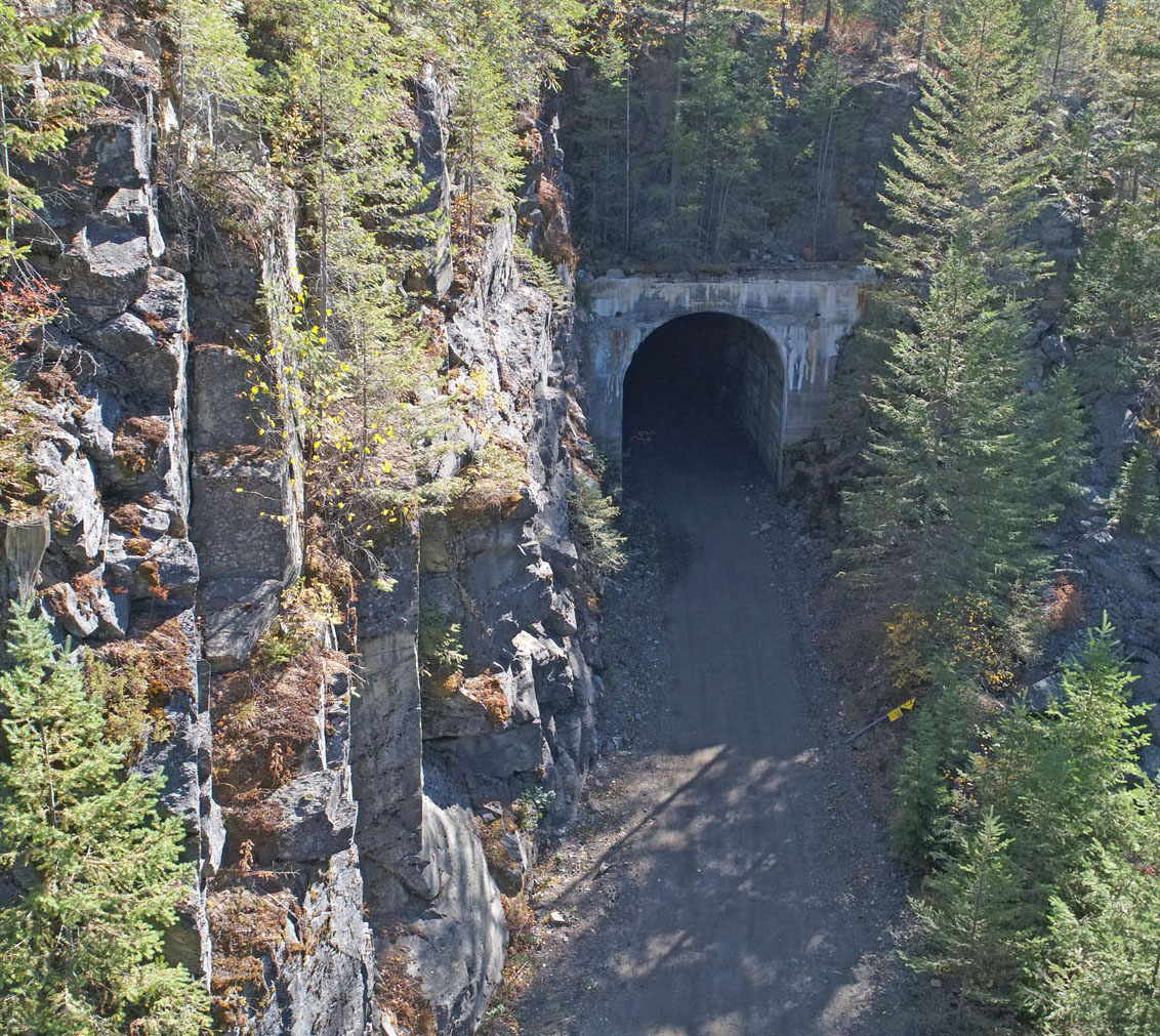
A drone photo of the prototype east tunnel portal.
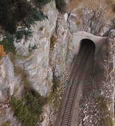
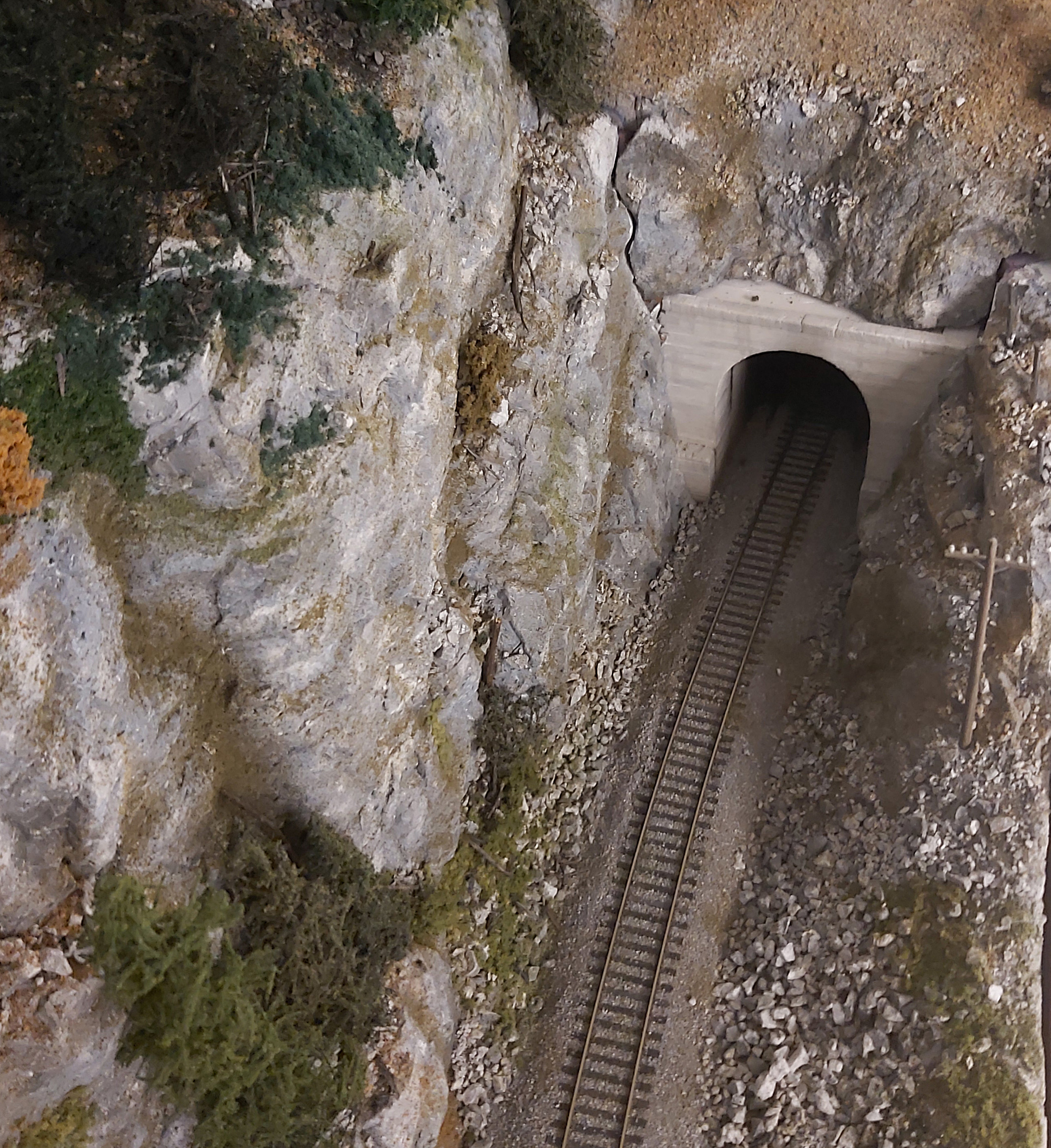
A photo of the model east tunnel portal.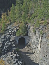
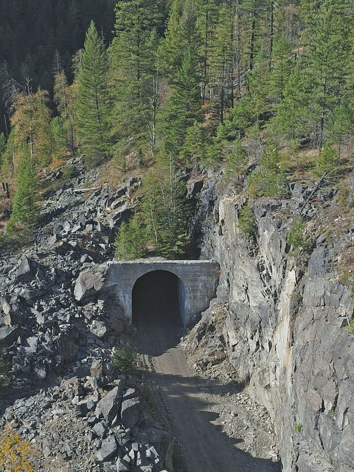
A drone photo of the prototype west tunnel portal.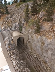
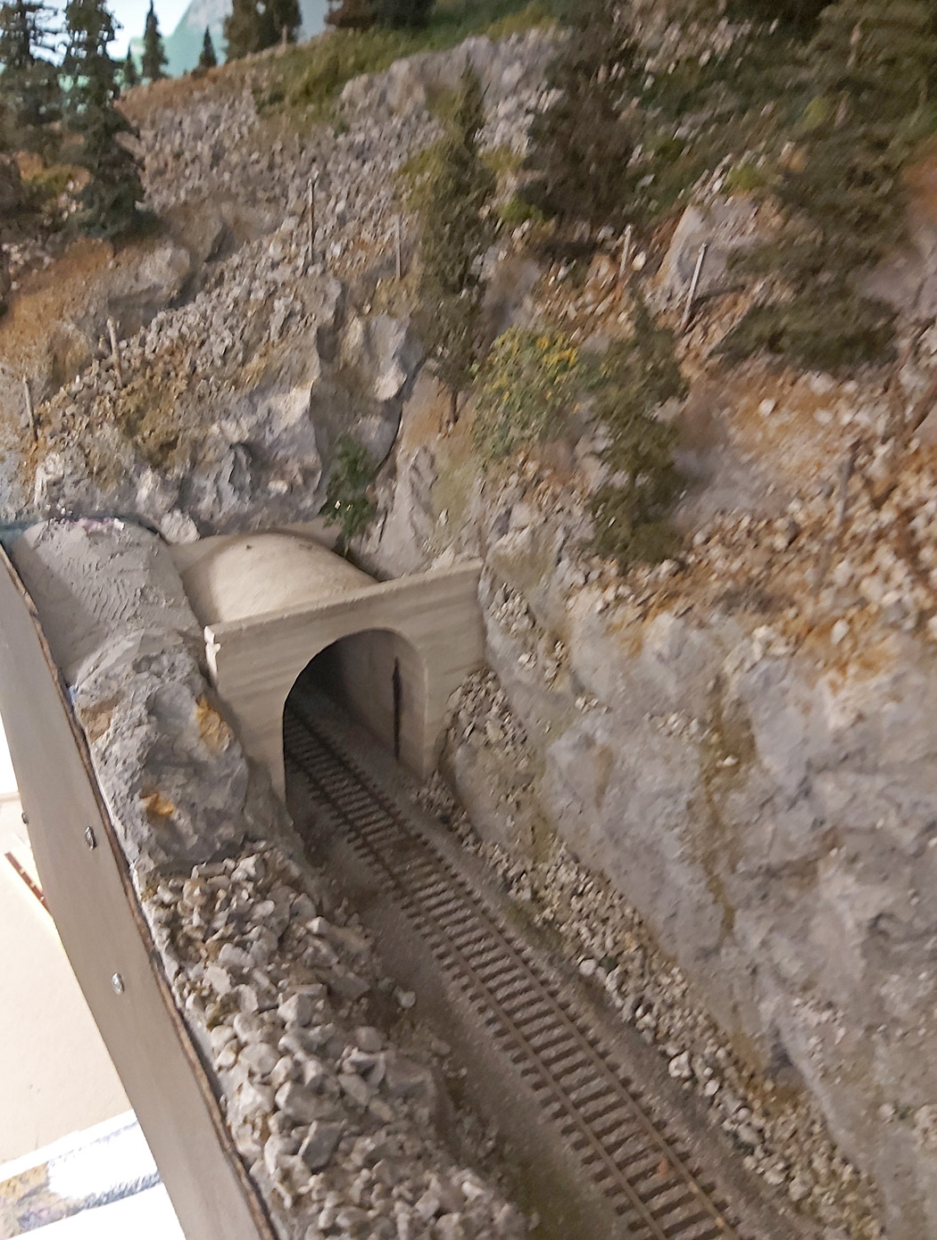
A photo of the model west tunnel portal.There is a really interesting scene that we wanted to emulate where McRae Creek runs adjacent to the mainline track. Depending on the time of year and amount of rainfall, this creek can be more like a bog, and we choose to model that look.
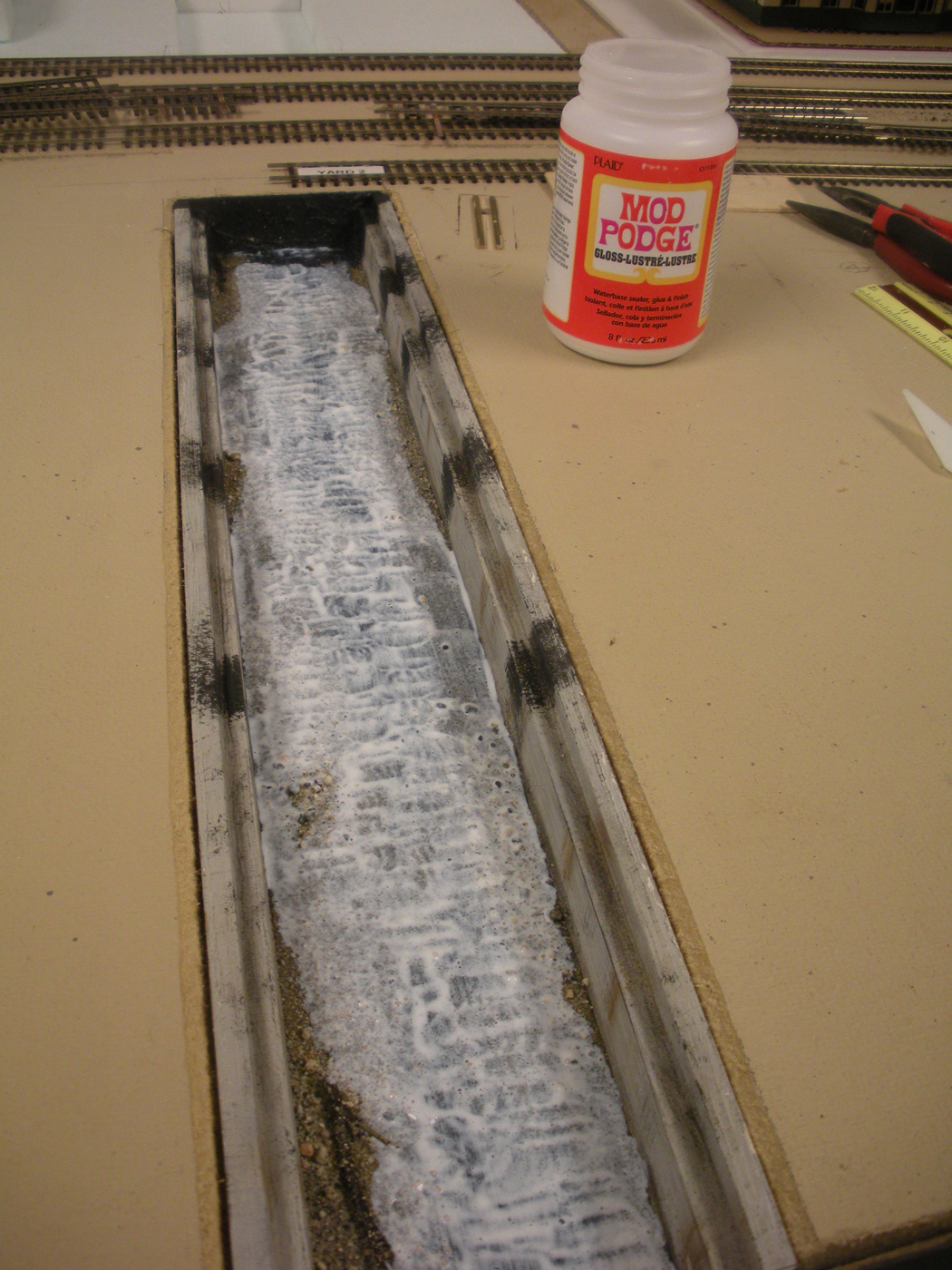
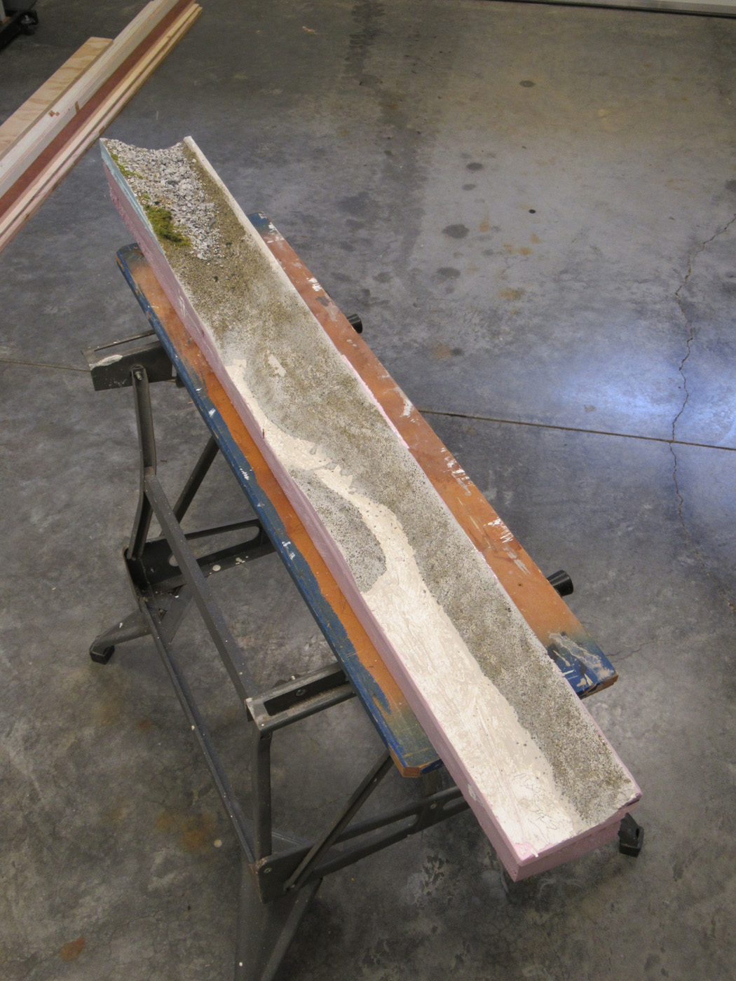
Two 4 foot long landforms make up the length of this creek, which were prepared and sceniced employing the typical techniques used elsewhere. These landforms were then permanently installed on the layout. The actual creek bed received a layer of gravel and fine sand and then was painted with acrylic paints in dark colors to match the prototype look. We choose to create the calm water by applying many coats of gloss MOD PODGE. The scenic materials were brought down to the water level just prior to the last couple of coats being done. To create the grass and weed on & in the water look, we carefully dusted the last wet coat of MOD PODGE with a mix of ground foams and static grass materials.

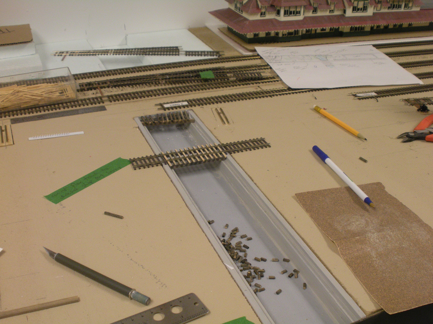
Here is one of the two 4 foot long landforms that comprise the creek bed structure.
This is the stretch of upper deck where the creek landforms will be placed.
The two landforms are now glued in position and ready for the next steps.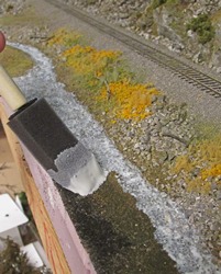
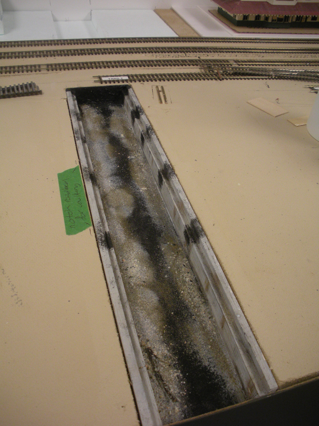
A foam brush was used to liberally apply the MOD PODGE gloss material in many coats to the creek bed.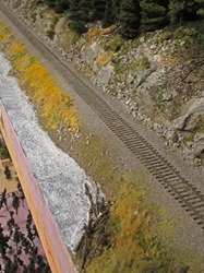
The material is a milky color upon initial application.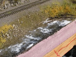
As the material dries, it become clearer, but still a bit murky due tot the textures and paint colors used on the creek bed.
The creek is quite narrow and overgrown where it originates in the upper part of the scene so the bed had more rocks and was more rugged. Numerous layers of the MOD PODGE gave the feeling of a tumbling creek.
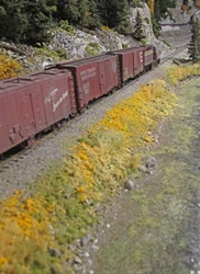
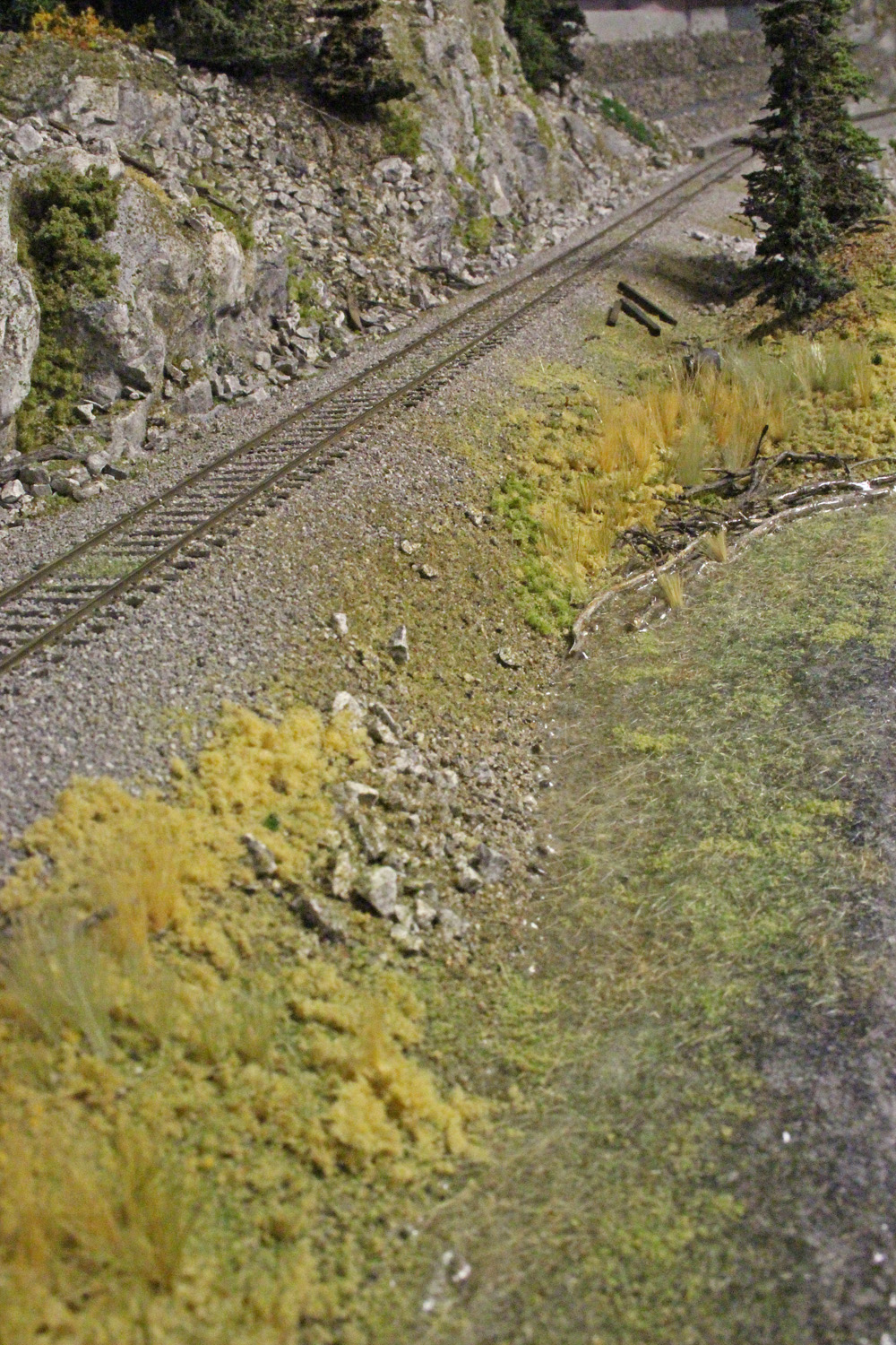
Here is a partial view of part of the final creek after we installed lots of tall grass, weeds etc and ground foam right down the water’s edge.
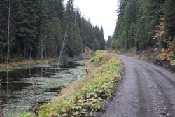
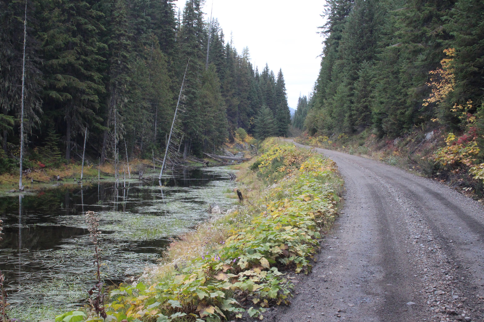
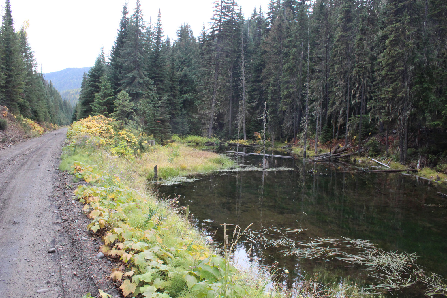
Two views of the prototype scene taken in October 2018.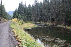


-
-
March 2020; Farron Siding Structures
-
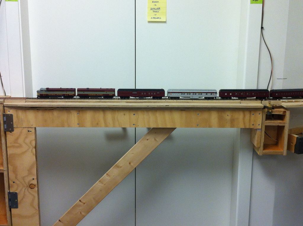
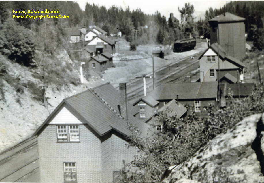
Farron was the Monashee Mountain summit on the line between Castlegar and Grand Forks, BC and was the base for the CPR helpers that worked the grades on either side of the pass. In my chosen era, there were only a few railroad structures located here. I am fortunate to have some photos and prototype CPR plans for many of the buildings. The most obscure structure is the combined station/residence building that served this location until the abandonment of the helper services.
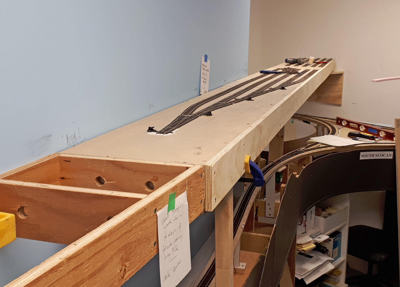
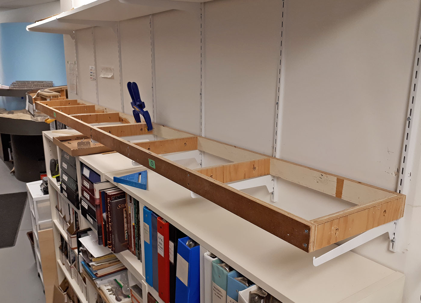
The challenge here is that the cluster of buildings is located on the aisle side of the shelf and therefore required an increase in the depth of the deck from 12” to 18”. Several mock ups were made using foamcore and arranged to emulate the prototype the best I could, which in turn determined how long this upper deck extension base needed to be. The current intention is that the Styrofoam base for this area will be removable so it doesn’t get in the way when we are working on the layout.
To date, the two section house mock ups are built and the Fife water tank model (built by Patrick Lawson) is being used as a stand in. Once I obtain some more photos of the station, I will make a mock up for it as well.
Here are a few progress photographs and copies of the prototype plans for the section house and 40,000 gallon enclosed water tank.
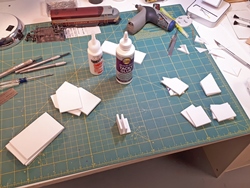
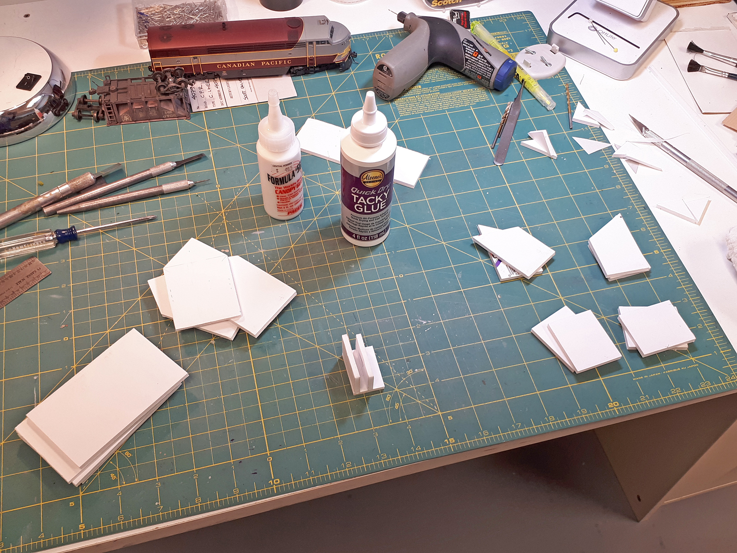
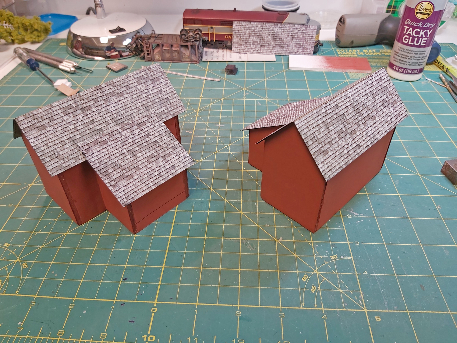
All the necessary wall components for the two section houses were cut out of white foam core sheets purchased from the local dollar store.

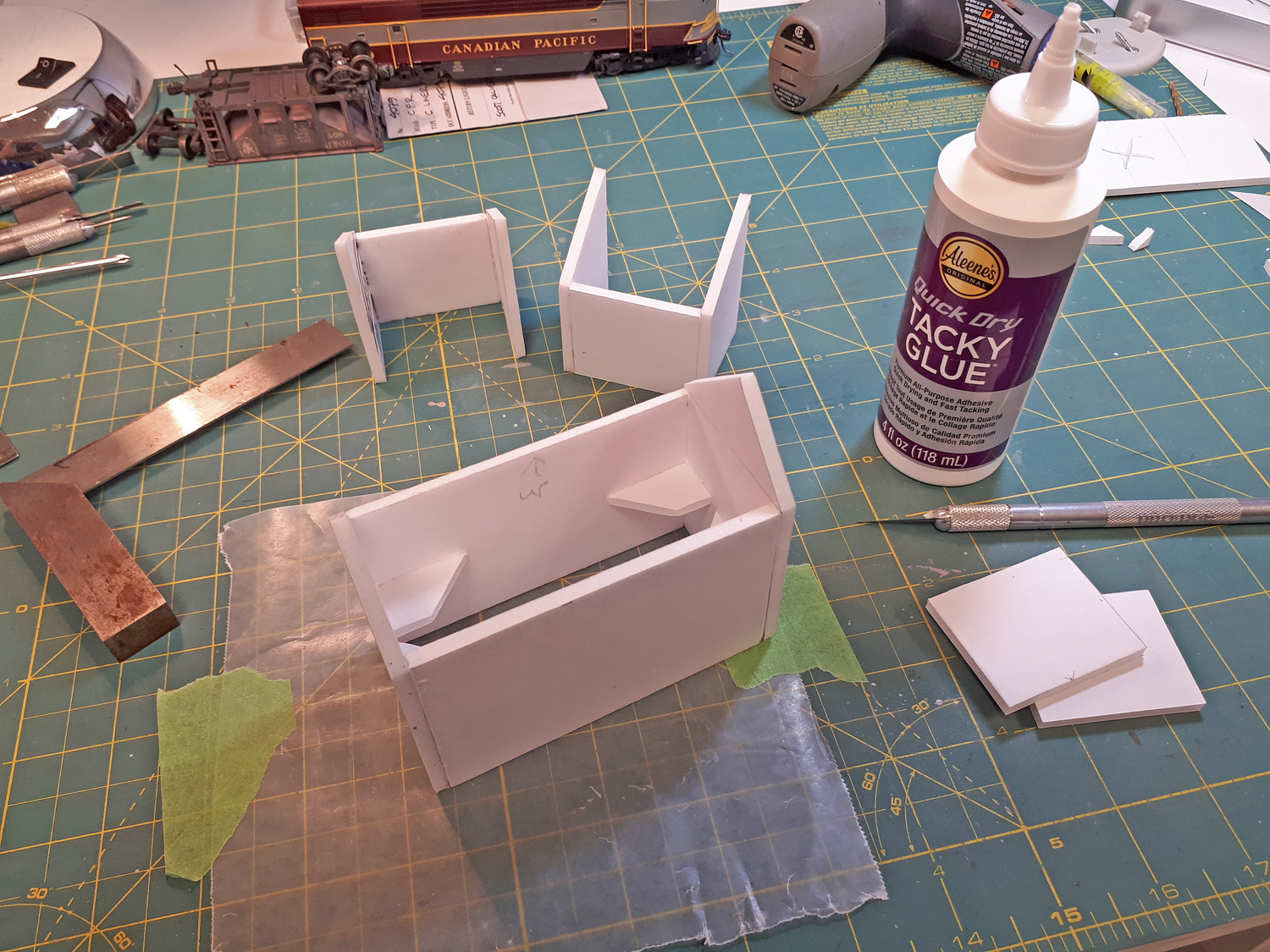
Assembly was completed using internal right angle pieces cut from scraps and Aleene’s TACKY glue was used to hold everything together. No need to be really precise here – we are only going for overall effect.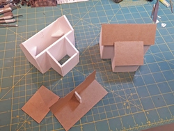
Here we see a completed building shell on the left, and one with the roof panels being test fit on the right. The roof panels are just scrap cardstock.
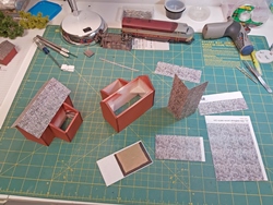
Before gluing the roof panels down, the buildings were spray painted with a rattle can. The color was selected to be “close enough”! I did learn – again – that the paint eats the exposed foam edges in the wall panels, so the corners look kinda crappy! The roof shingles are paper prints I bought from CLEVER Models, glued on with 3M spray adhesive. They actually look pretty good and I am pondering whether with a little weathering, they might be used for the final models.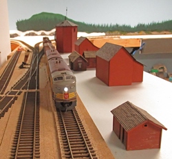
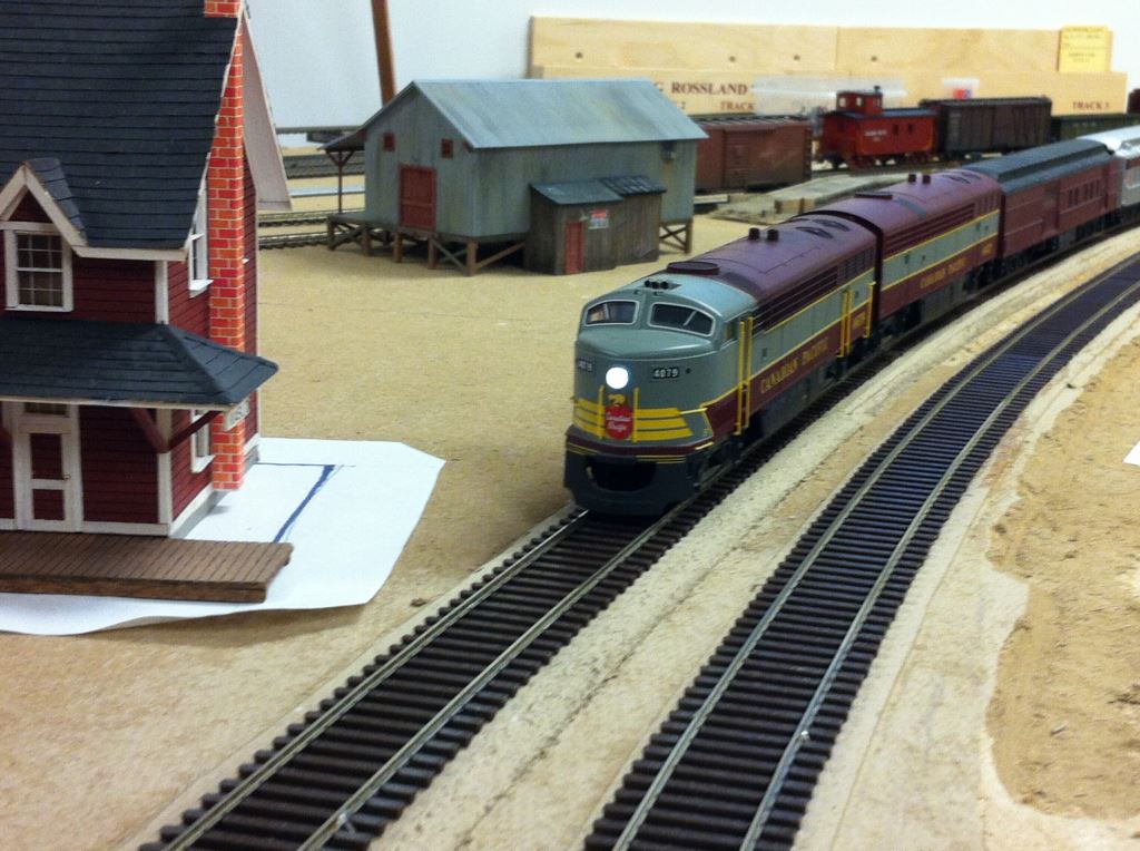
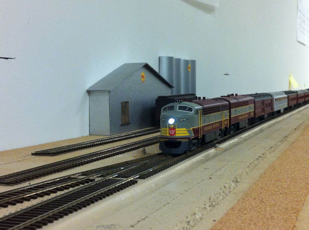
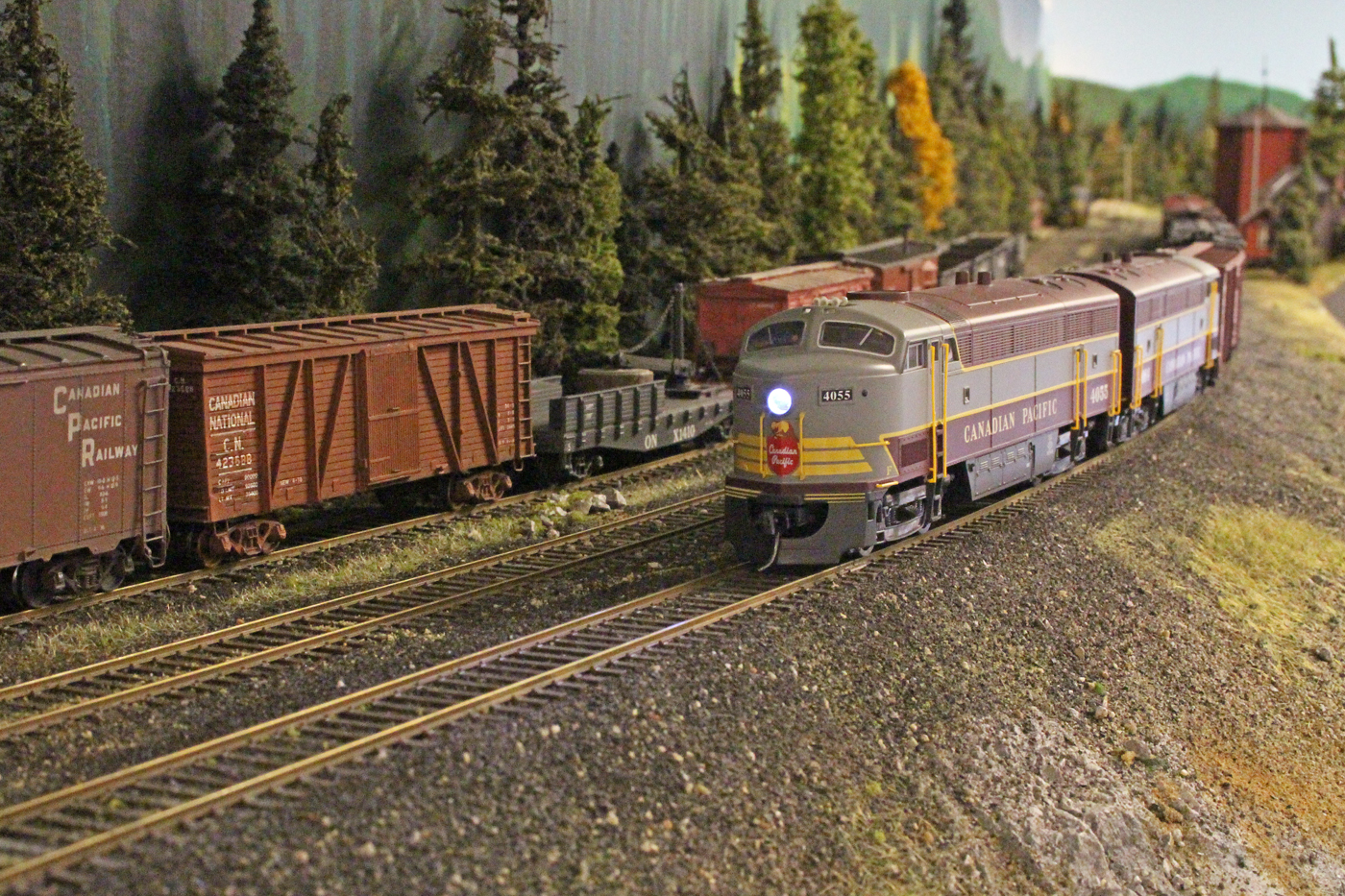
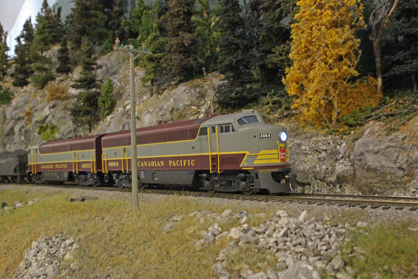
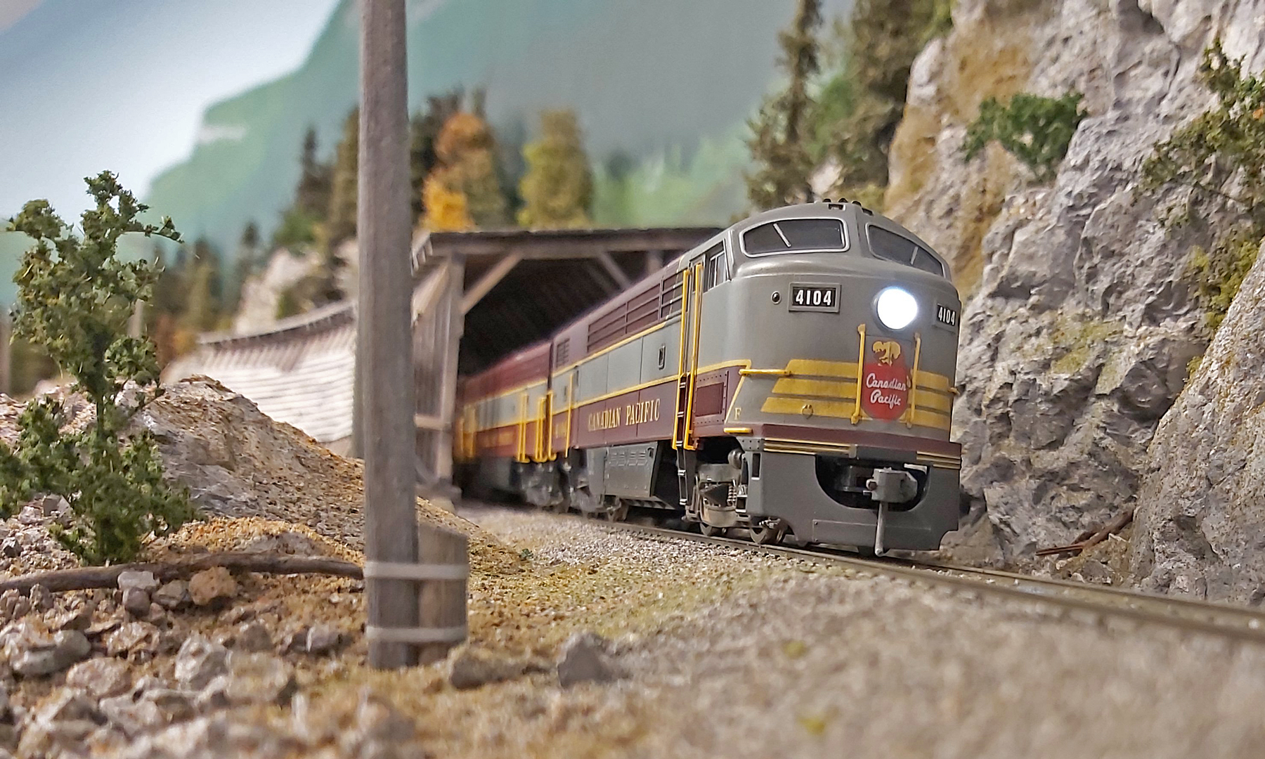
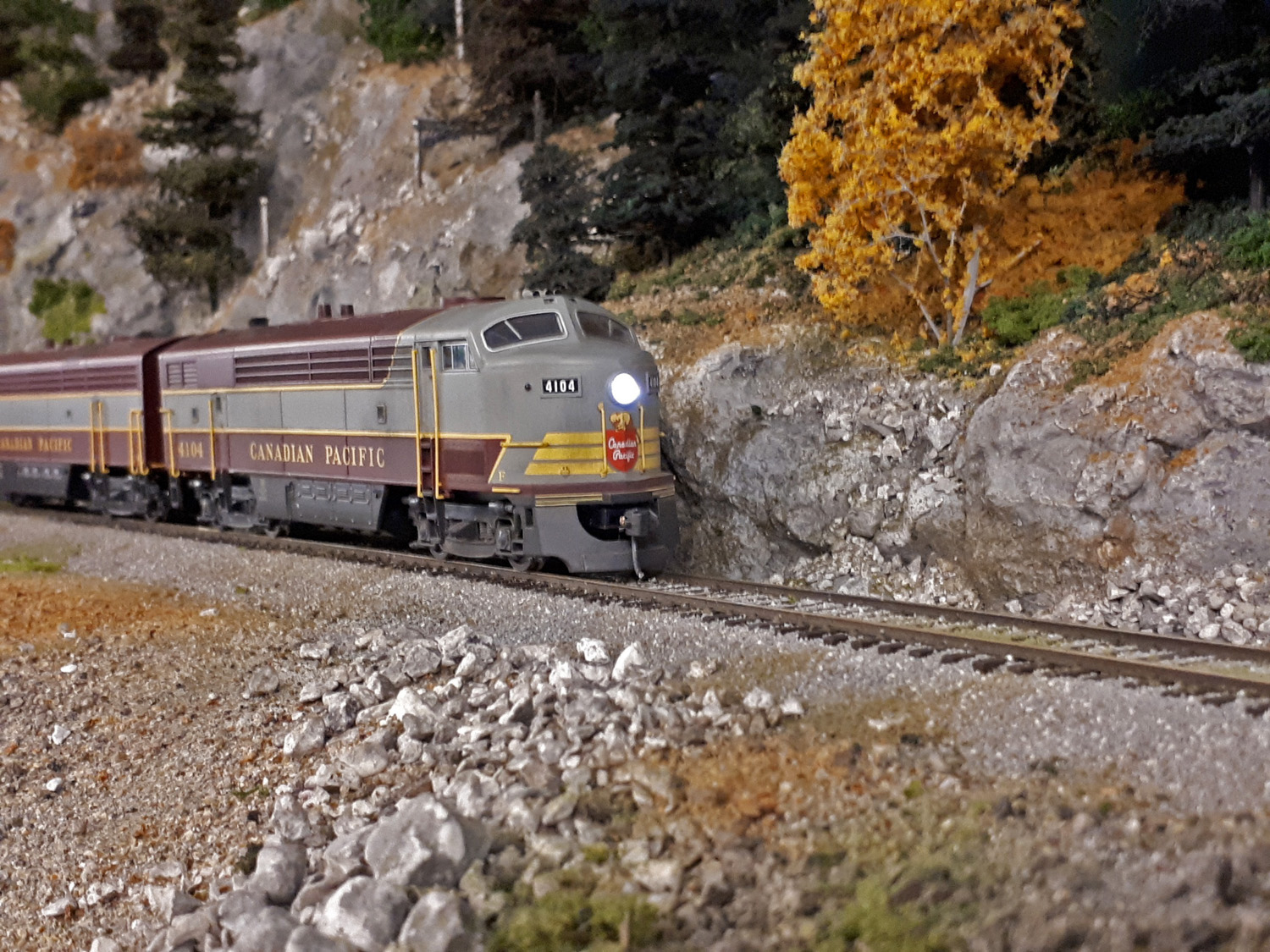
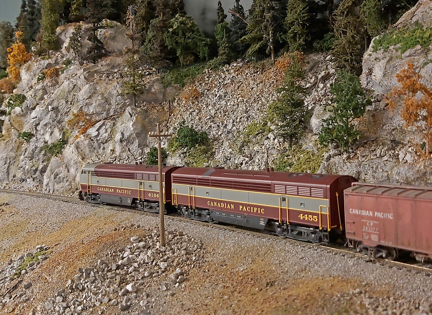
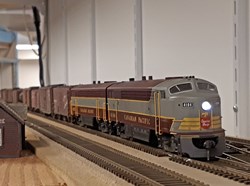
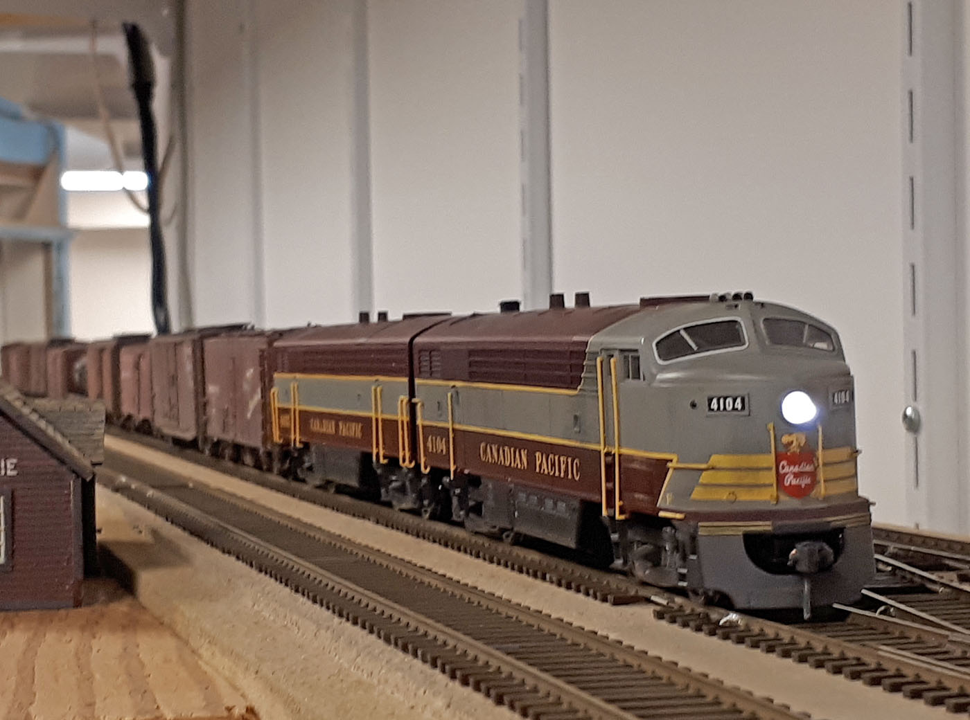
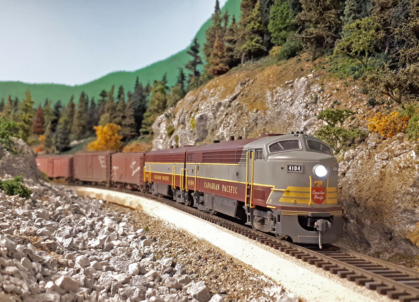
As I work on the layout, I am always exploring vantage points for photography. Here we see Extra 4104 East holding the main while waiting for a meet and further orders.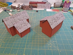
Here are the two completed mock up buildings. They certainly won’t win any contests, but are good enough for now.
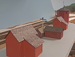
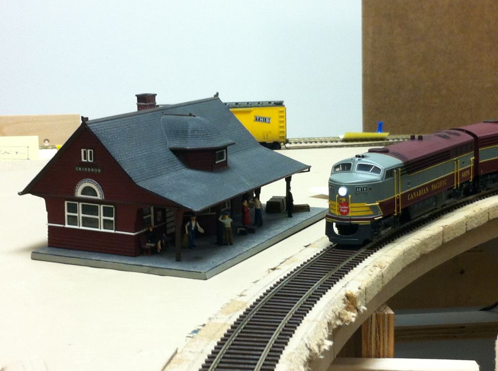
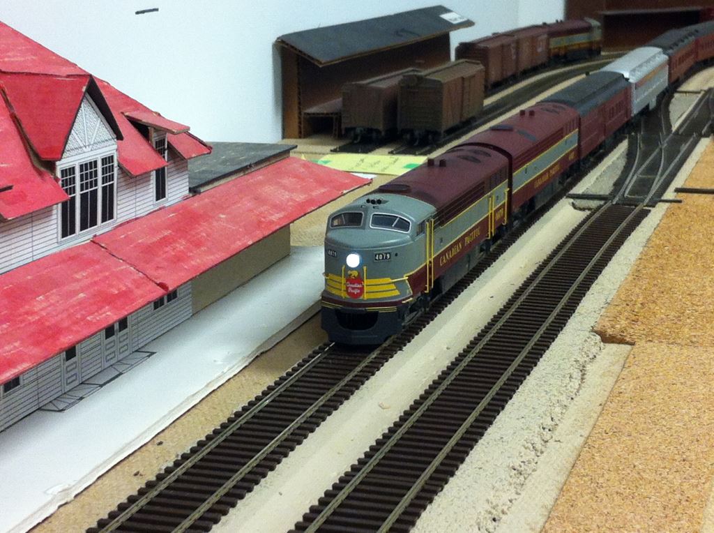
Here is a low angle photo that attempts to capture the same feel as the adjacent prototype photo.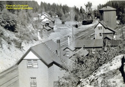
Prototype photo provided by Bruce Rohn.
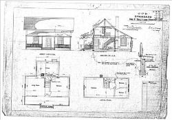
Section House No. 2 Drawings (PDF)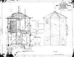

No.2 Enclosed Water Tank (PDF)


-
-
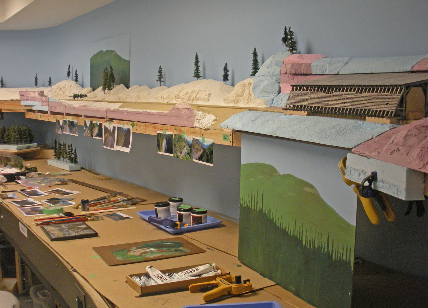
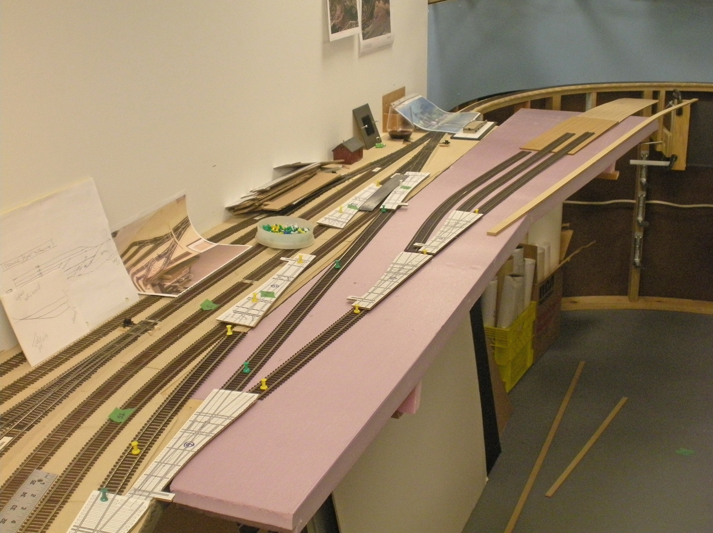
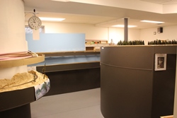
Spring 2020; Farron Scenery
-
The track in Farron was installed just prior to VanRail 2019 so we could use the newly extended mainline. There has been no further work on this area until recently, when I decided it was time to continue scenic efforts through this area and blend it with the adjacent scenery that was nearing completion.
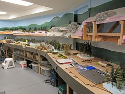
Being on the upper deck and directly over my workbench area, we again elected to use the Styrofoam landform methodology as was being used elsewhere to minimize the mess in the actual layout room. This area includes about 25 feet of 12” deep deck and the actual wye area as well. The topography is much less rugged than what I have been dealing with to date – which was a welcome relief!
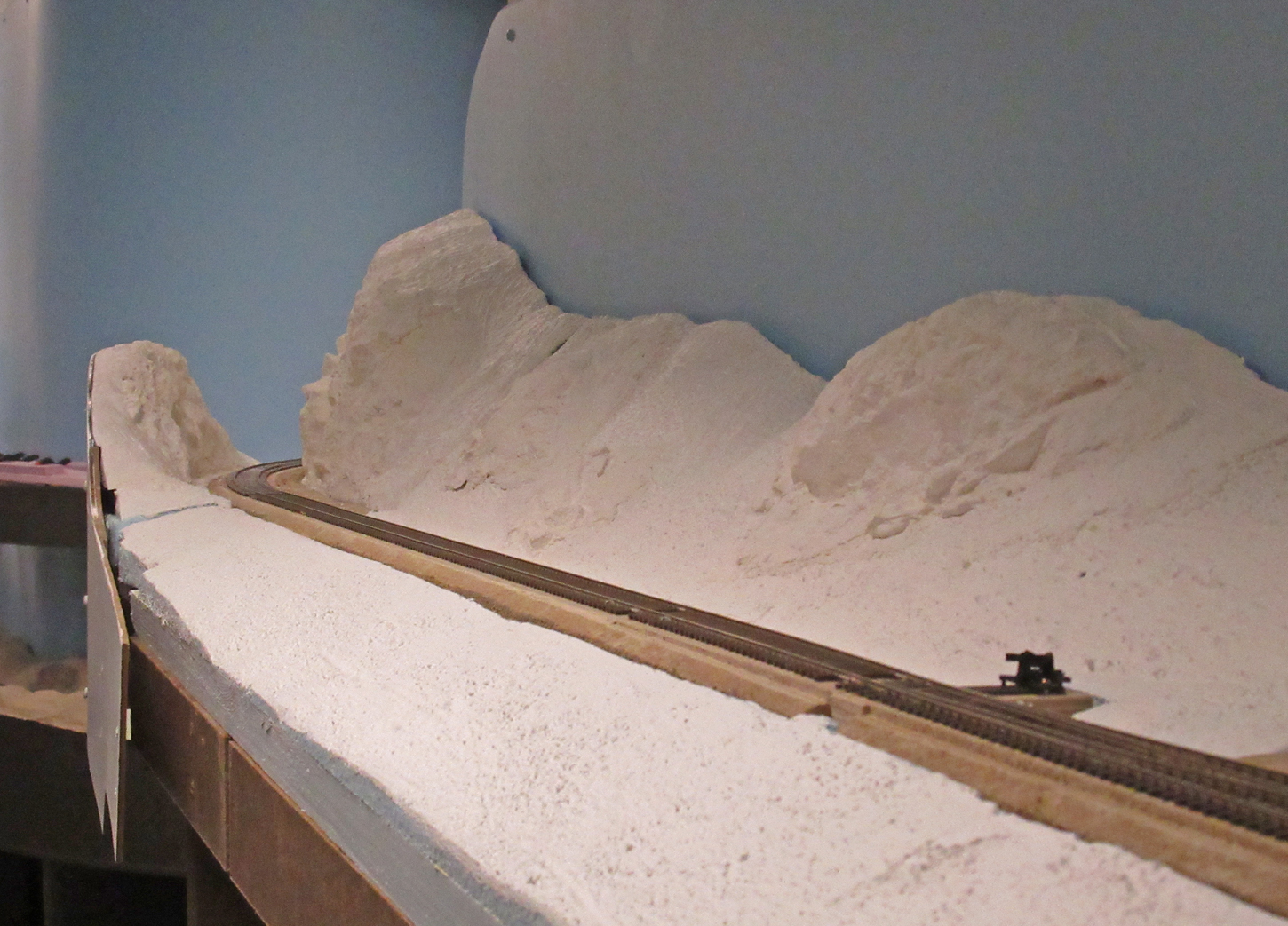
The landforms are completed and have received the necessary rock castings and base plaster coat for now. The scenic texturing phase on these landforms will be undertaken in the coming months using materials and colors similar to those utilized on the adjacent completed scenes because Farron is in the same valley.
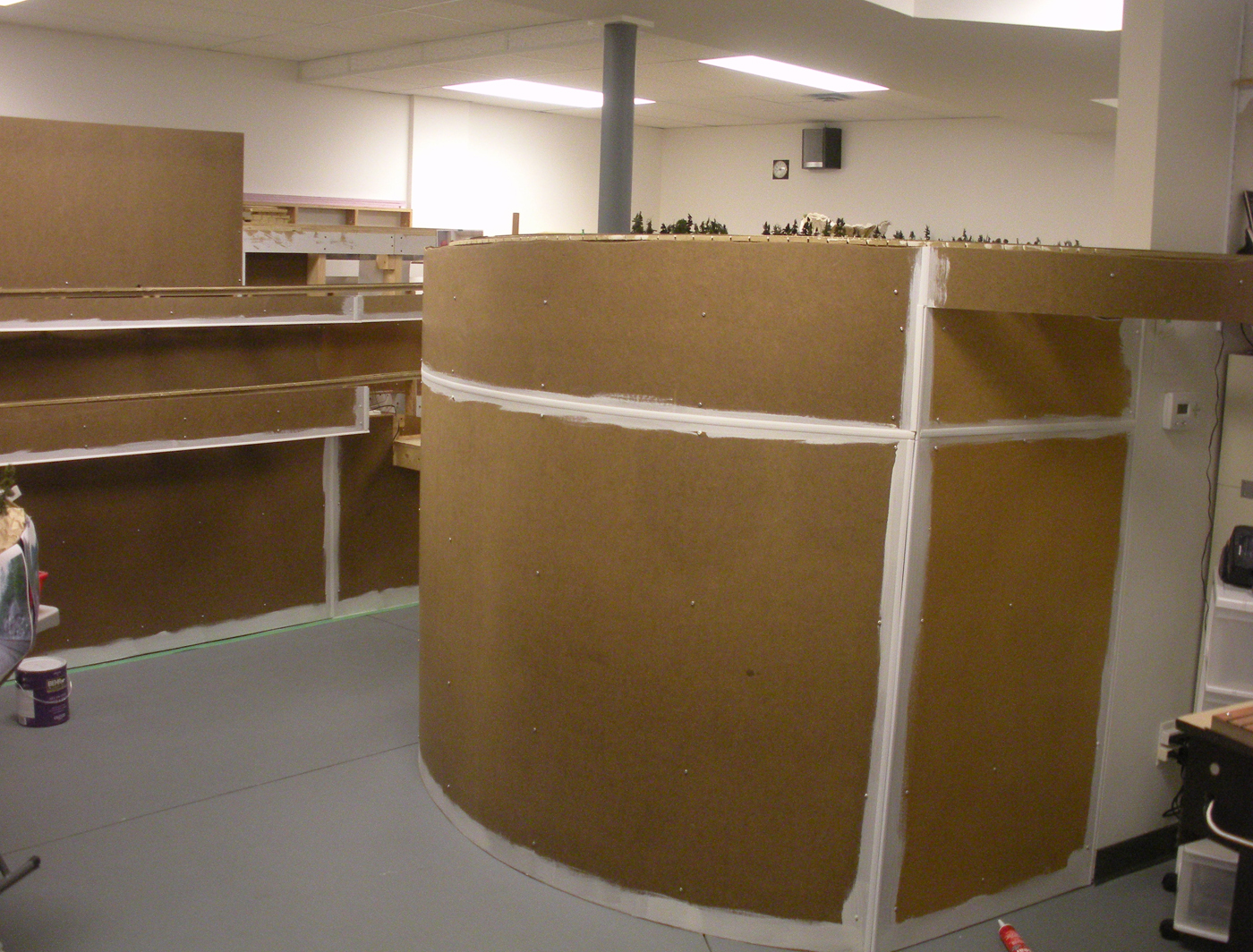
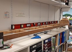
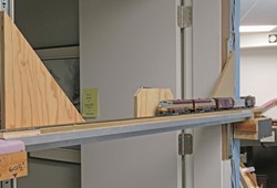
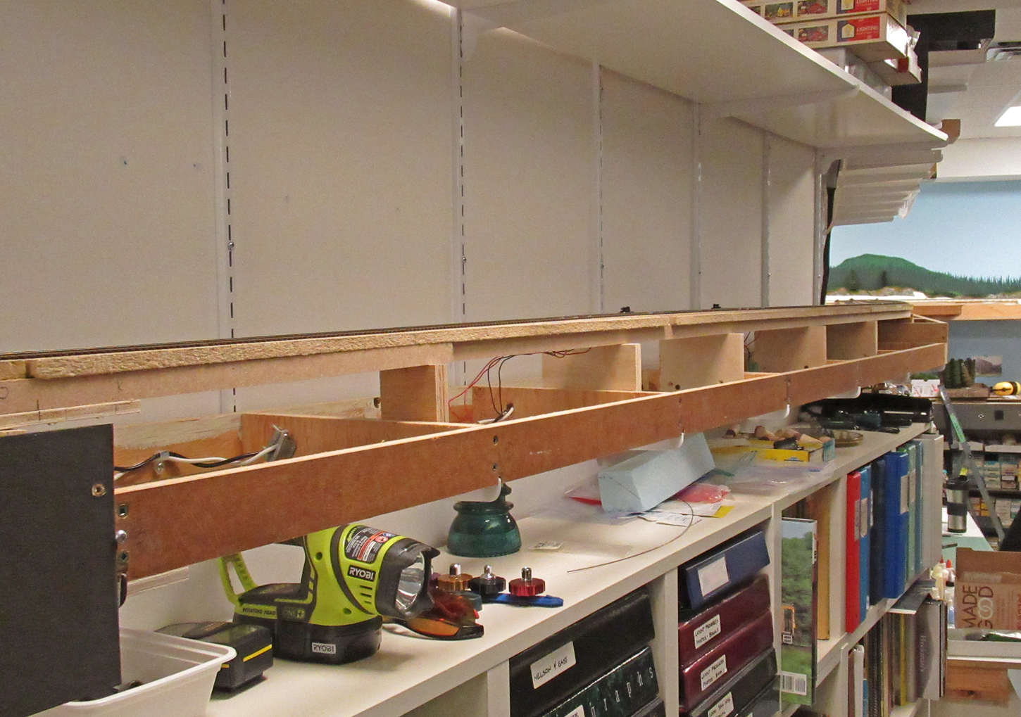
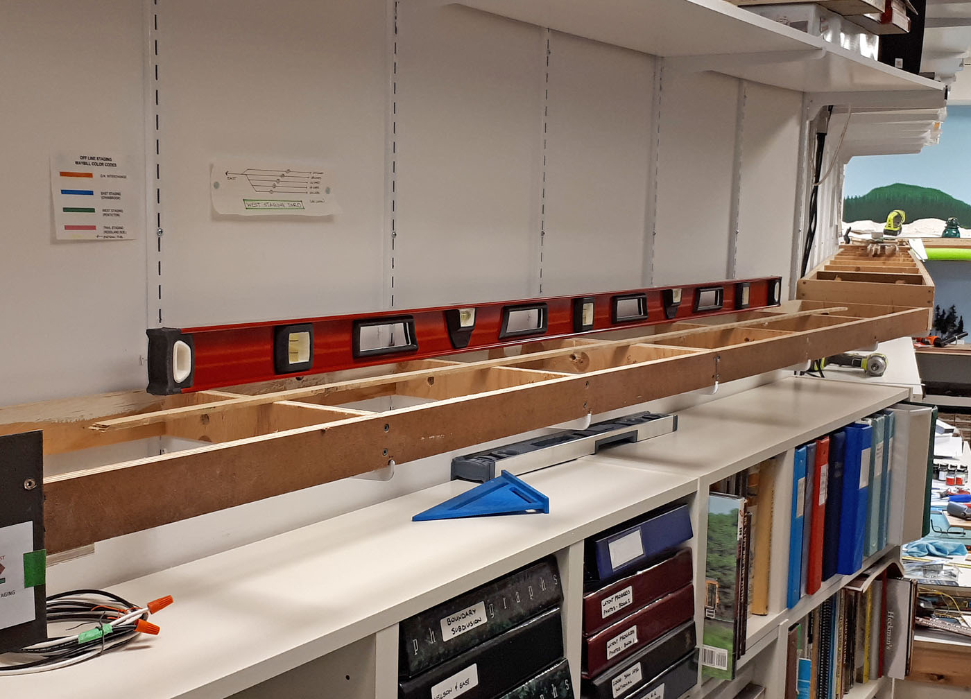
This area also required some additional fascia construction and modifications, as well as installation of the necessary backdrop to cover the metal wall shelving bracket system. Plywood strapping was glued to the wall and 24 feet of 1/8” hardboard panelling was installed. All joints and screws were mudded and sanded after which the entire length received a coat of primer followed by a coat of the standard sky blue latex paint. Further backdrop paining will be undertaken in the coming months.
Before proceeding to complete this area, all the turnout switch machines and controls need to be installed and tested. We are now undertaking those tasks.
Below are a series of chronological photos capturing the general efforts to date.
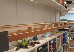
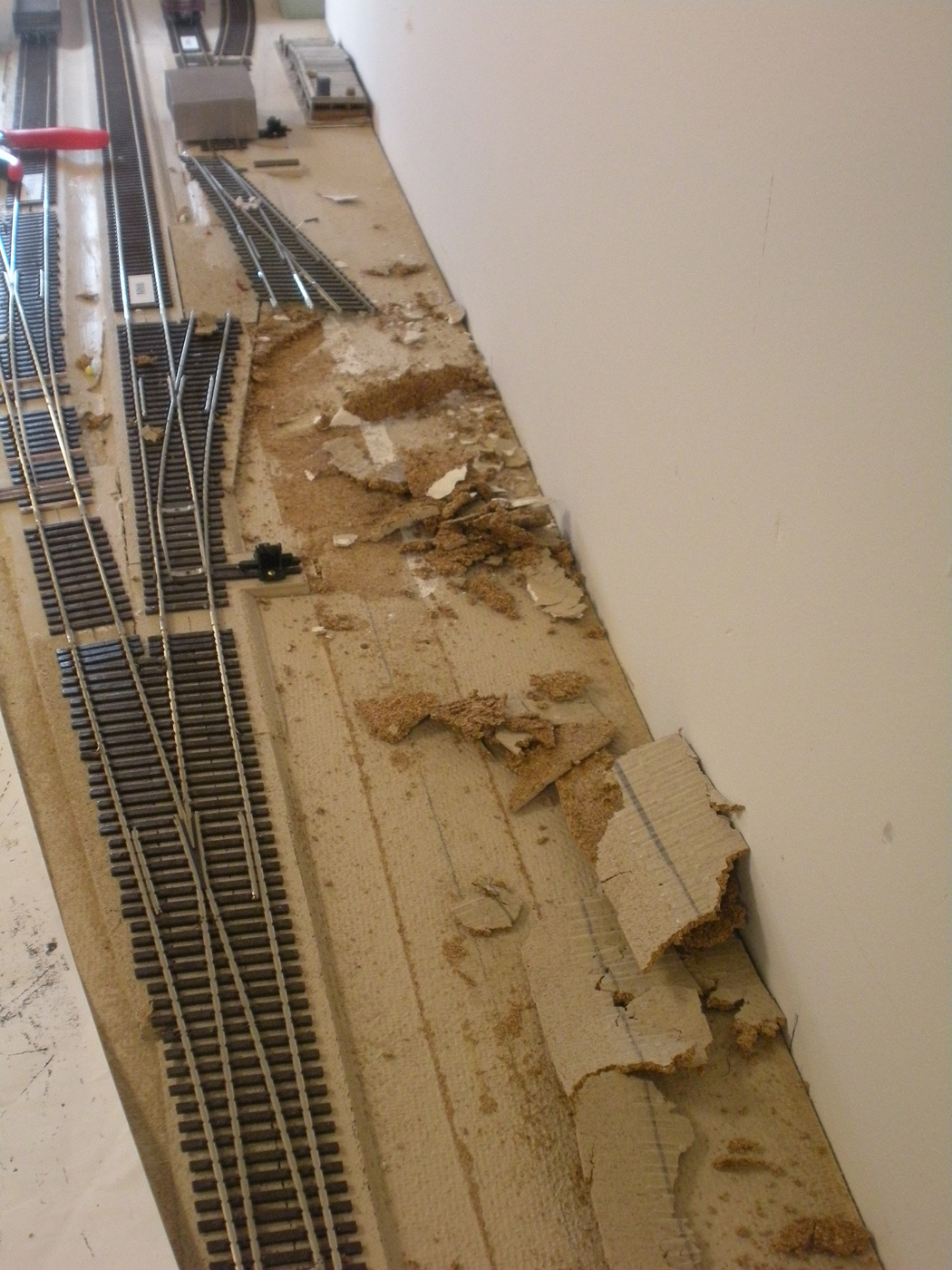
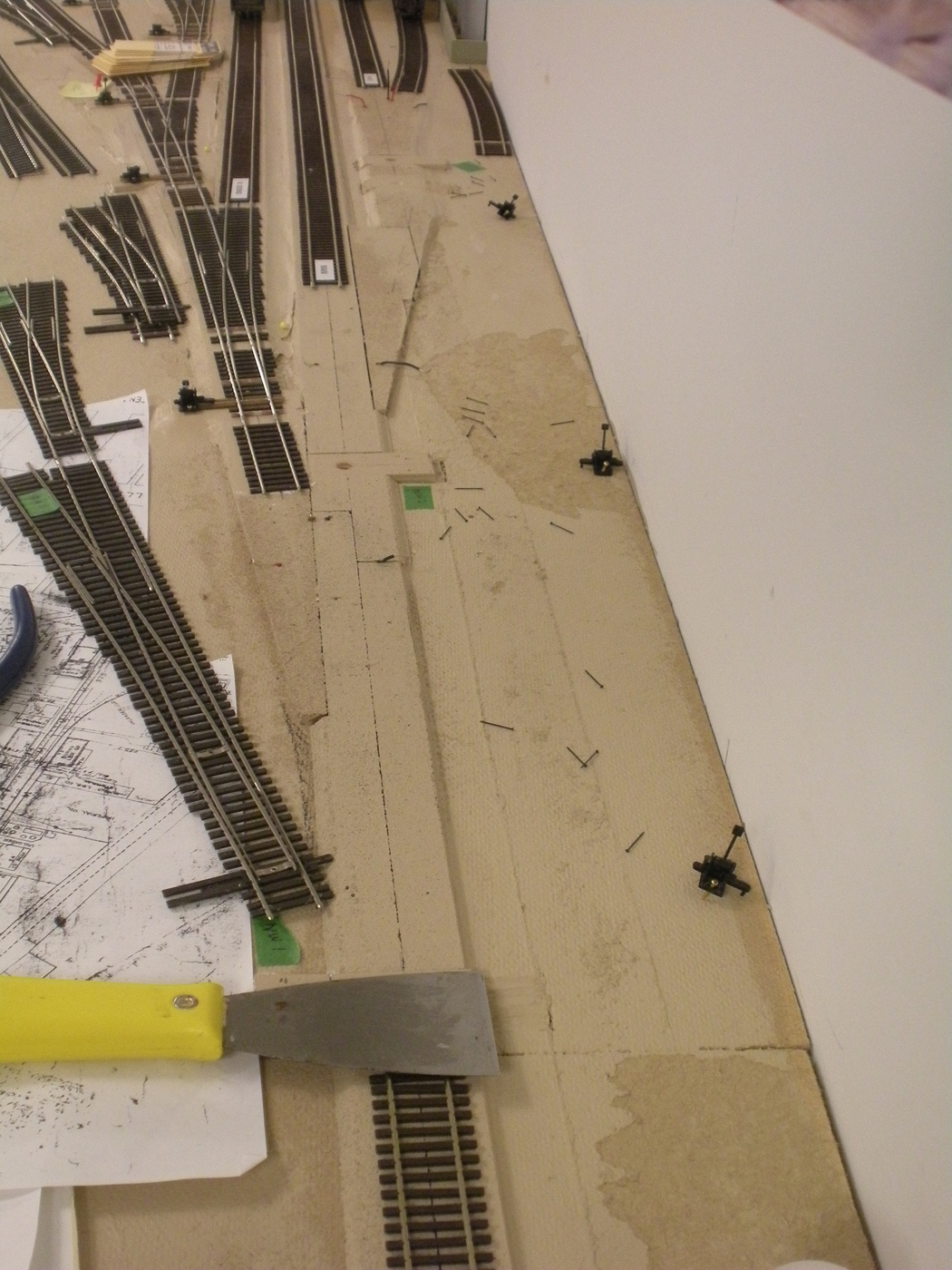
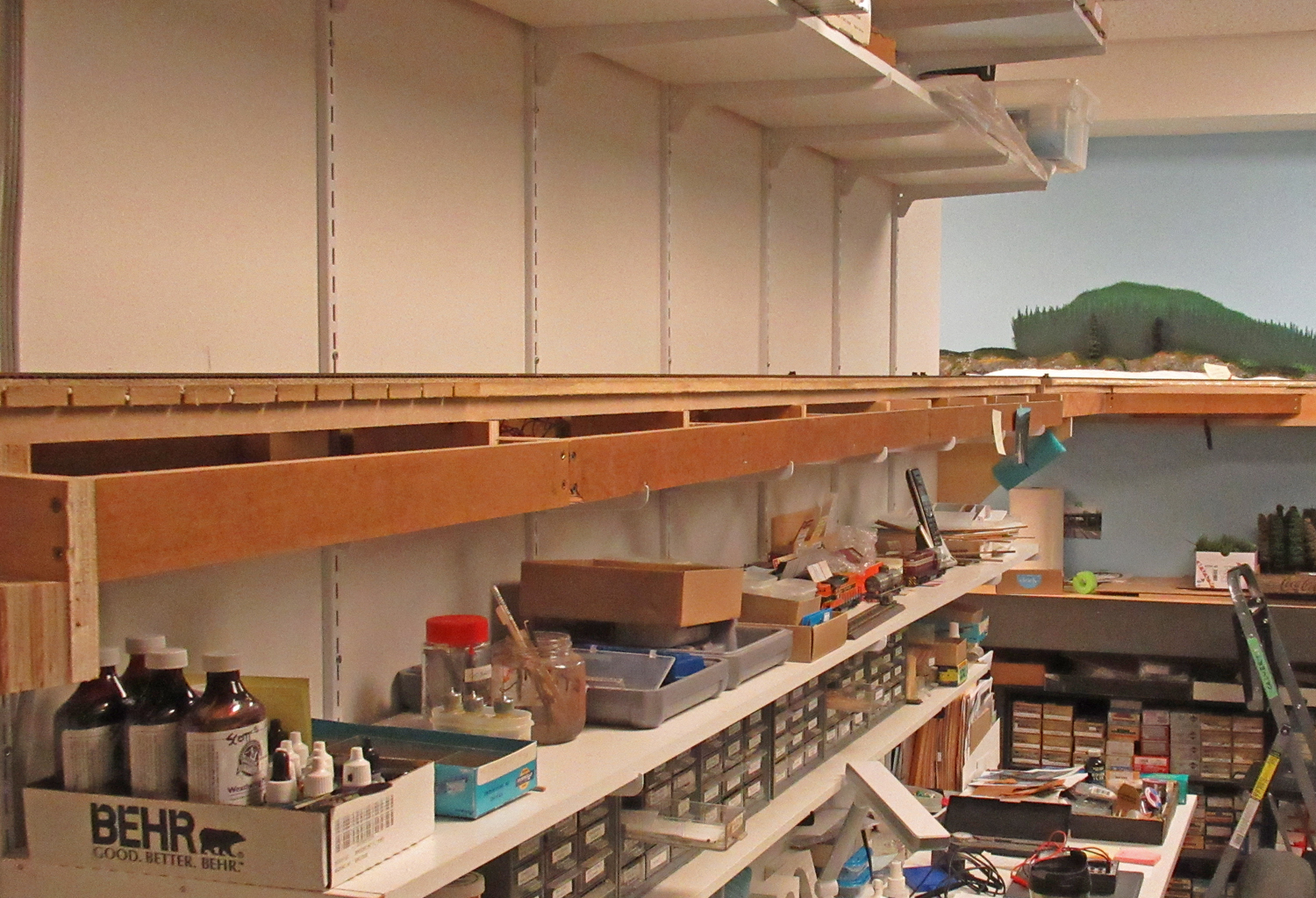
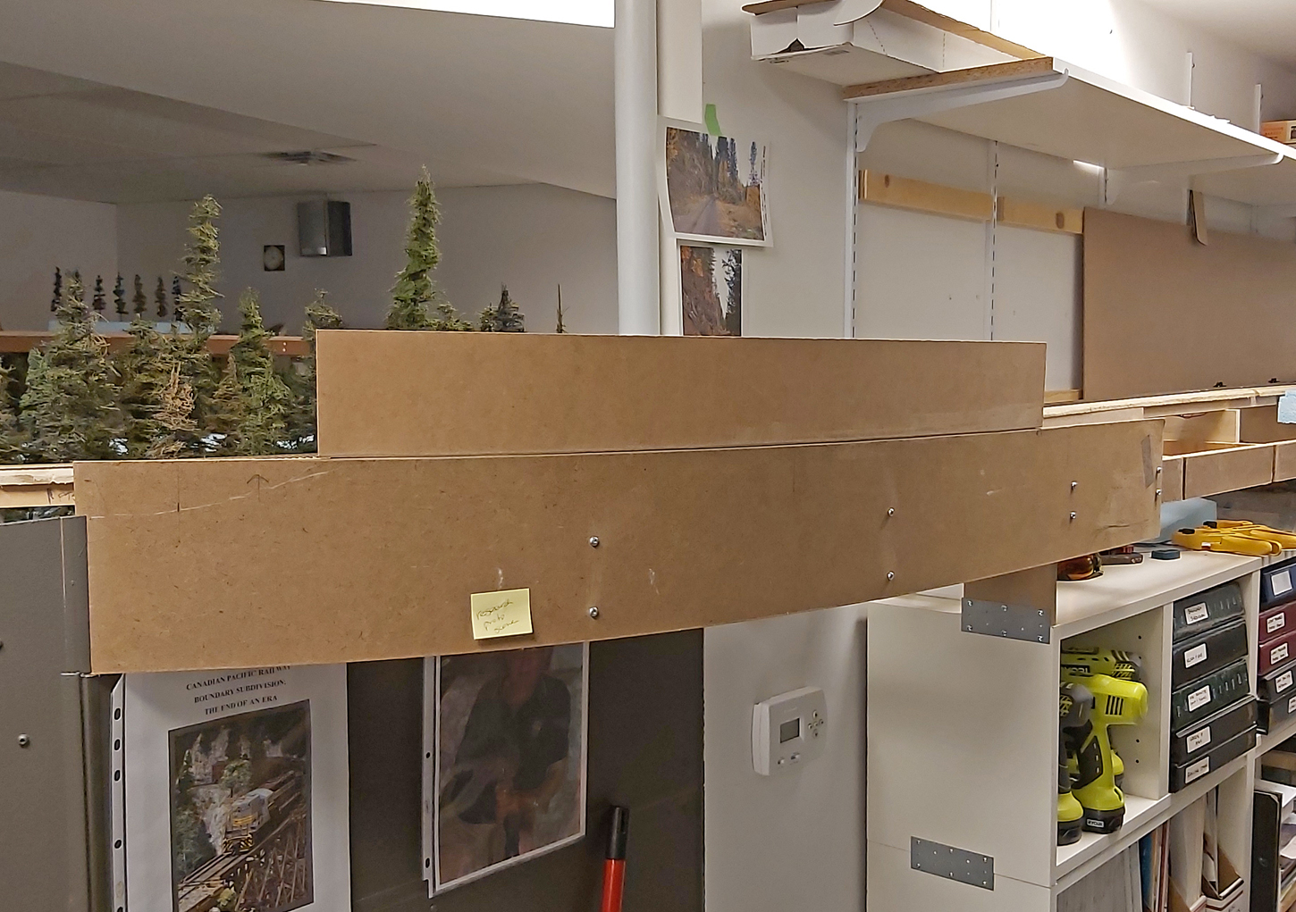
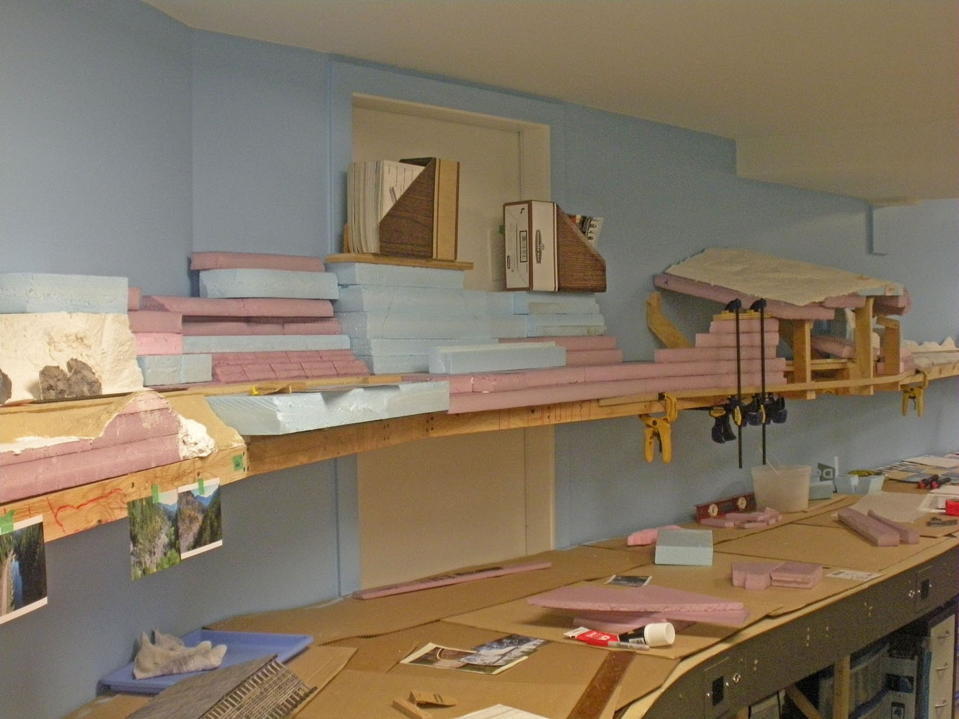
Here is where we started. This view is looking westward at a location just east of the actual Farron siding area.
Here is another view before we started. This is looking westward at a location part way along the Farron siding.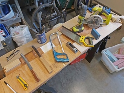
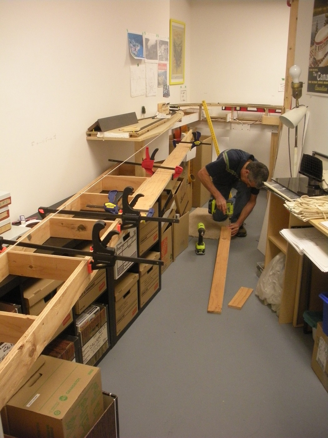
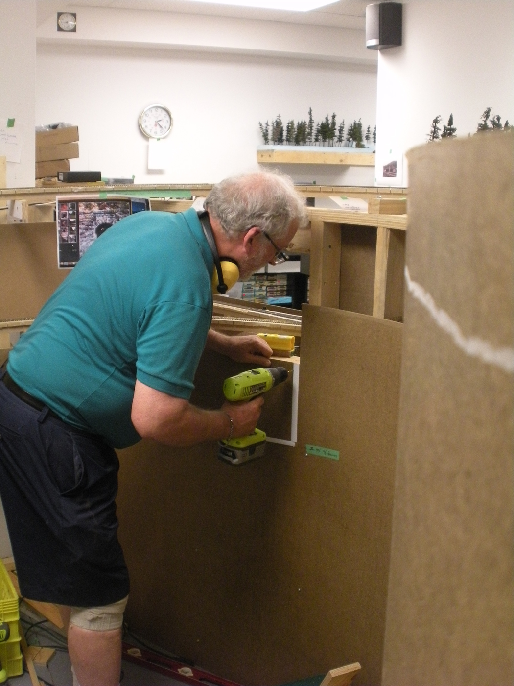
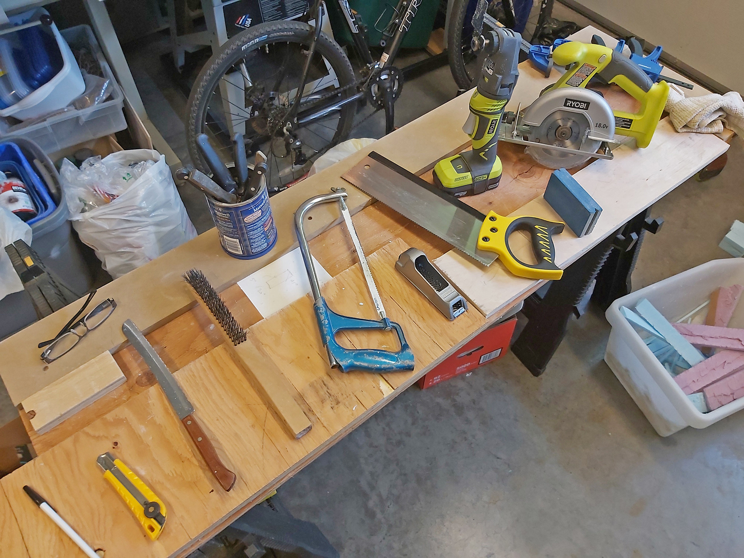
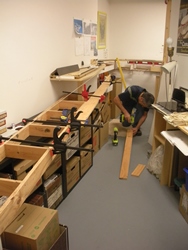
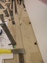
Here are my tools of choice. Everything from a kitchen bread knife to the Ryobi cordless multi tool. In addition to these, the shop vac is essential to manage the resultant bits generated while cutting the foam. One thing not shown is a hot wire cutter! While I do have one of those tools, I frankly find it a waste of money because it struggles with cutting through any thicker foam sheets and is useless for the type of work I am doing. Plus, they do generate a toxic odor so a breathing mask is necessary.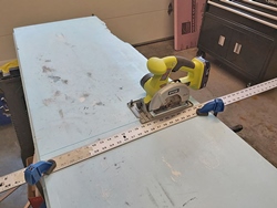
For this area of scenery, I decided to try my cordless skill saw for the many straight cuts I needed to make. It worked great; however, I did have the shop vac running to suck up the foam particles that the saw generated while cutting.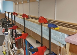
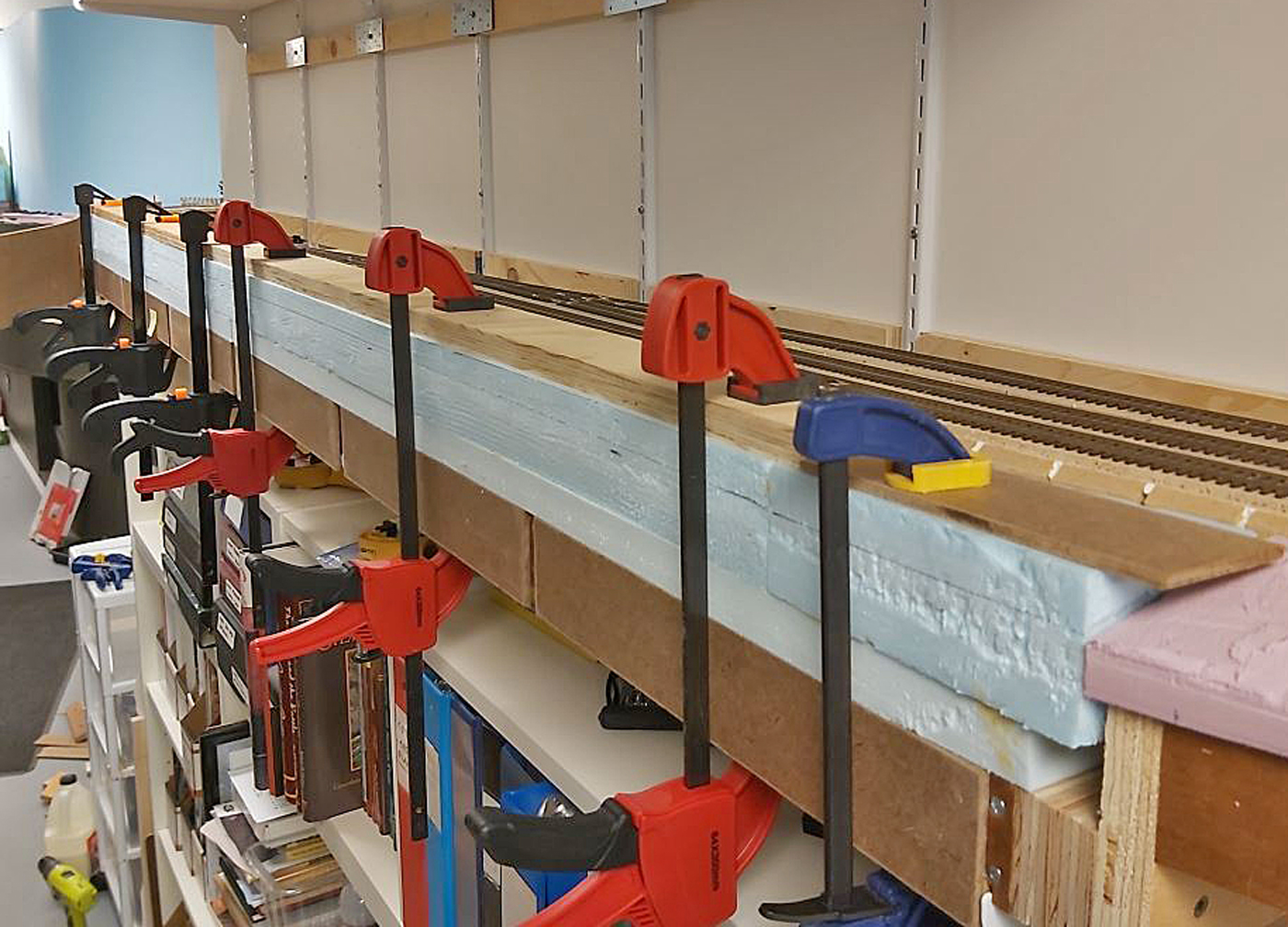
This is two 4 foot long sections each comprised of layers of foam which were glued together and then clamped against the layout framing until the foam glue dries.
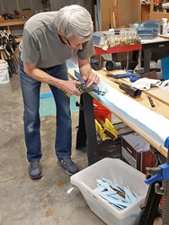
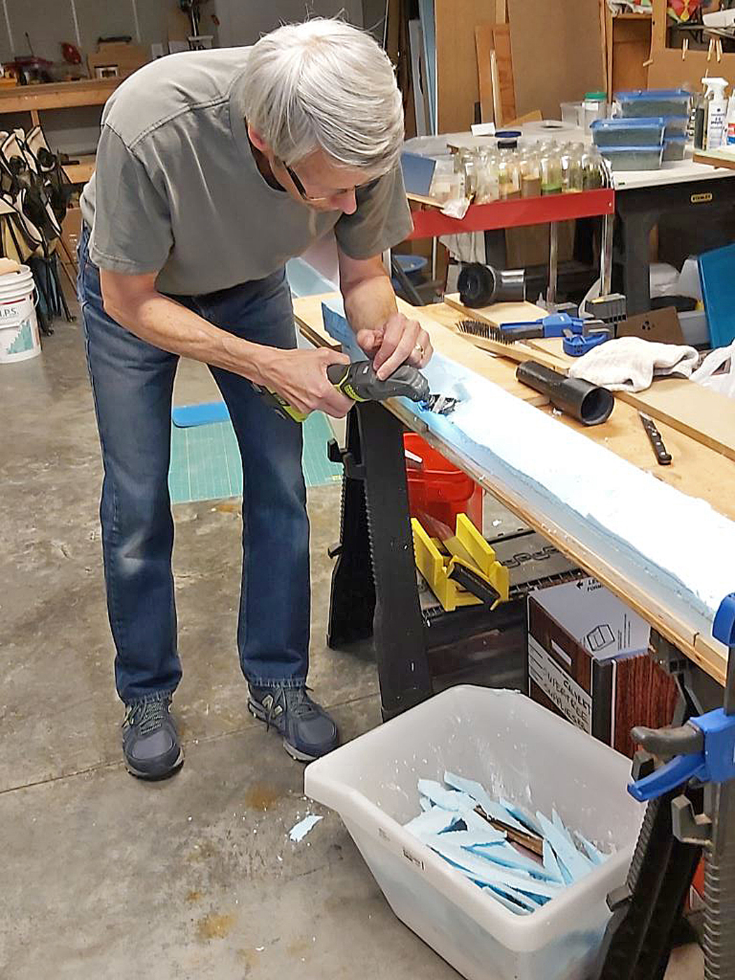
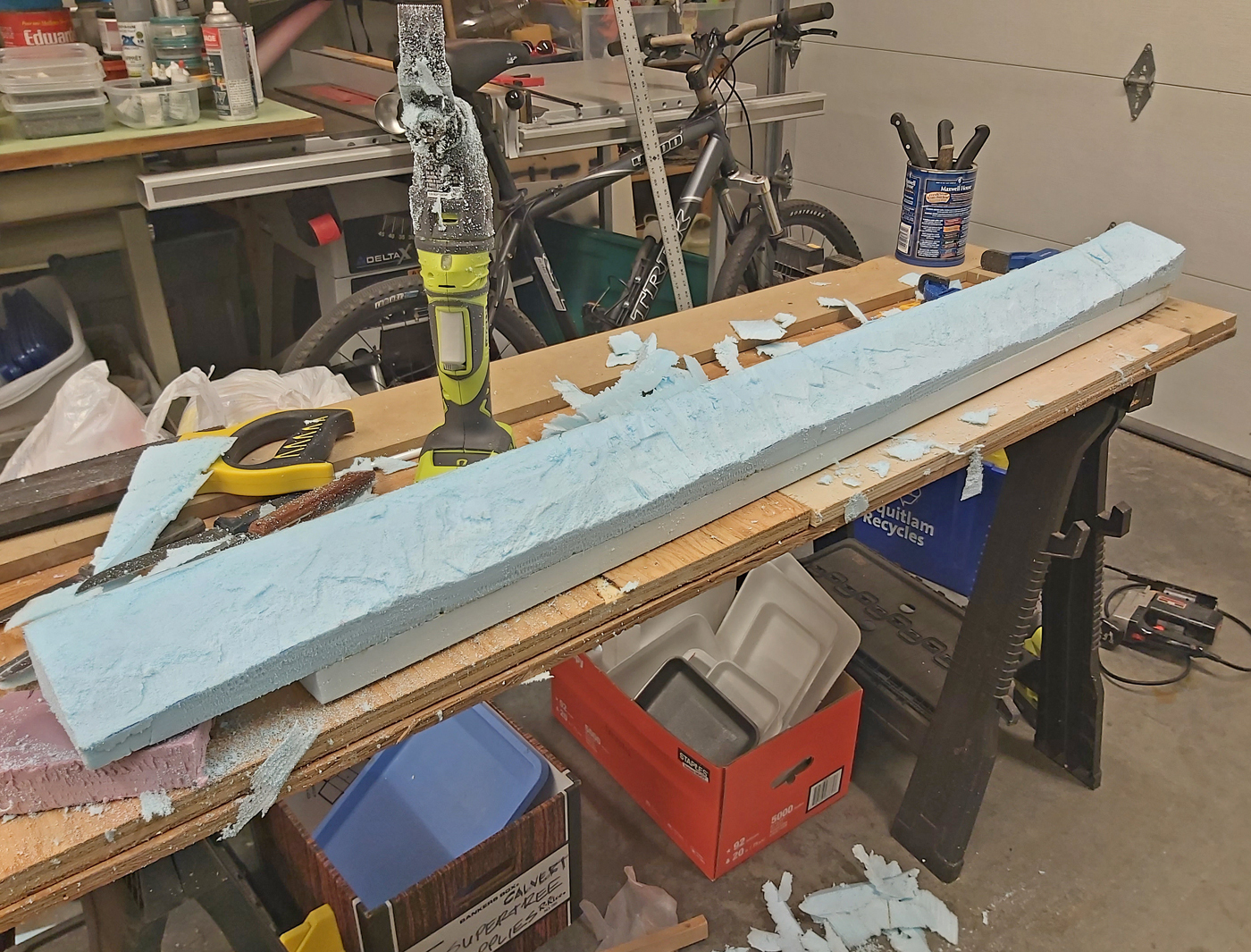
Here I am using the multi-tool to trim the downhill slope along one of the 4 foot long sections. Note the plastic tote on the floor to catch some of the falling pieces.
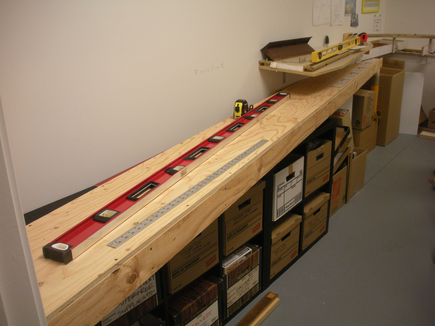
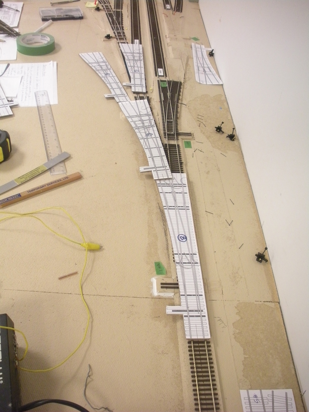
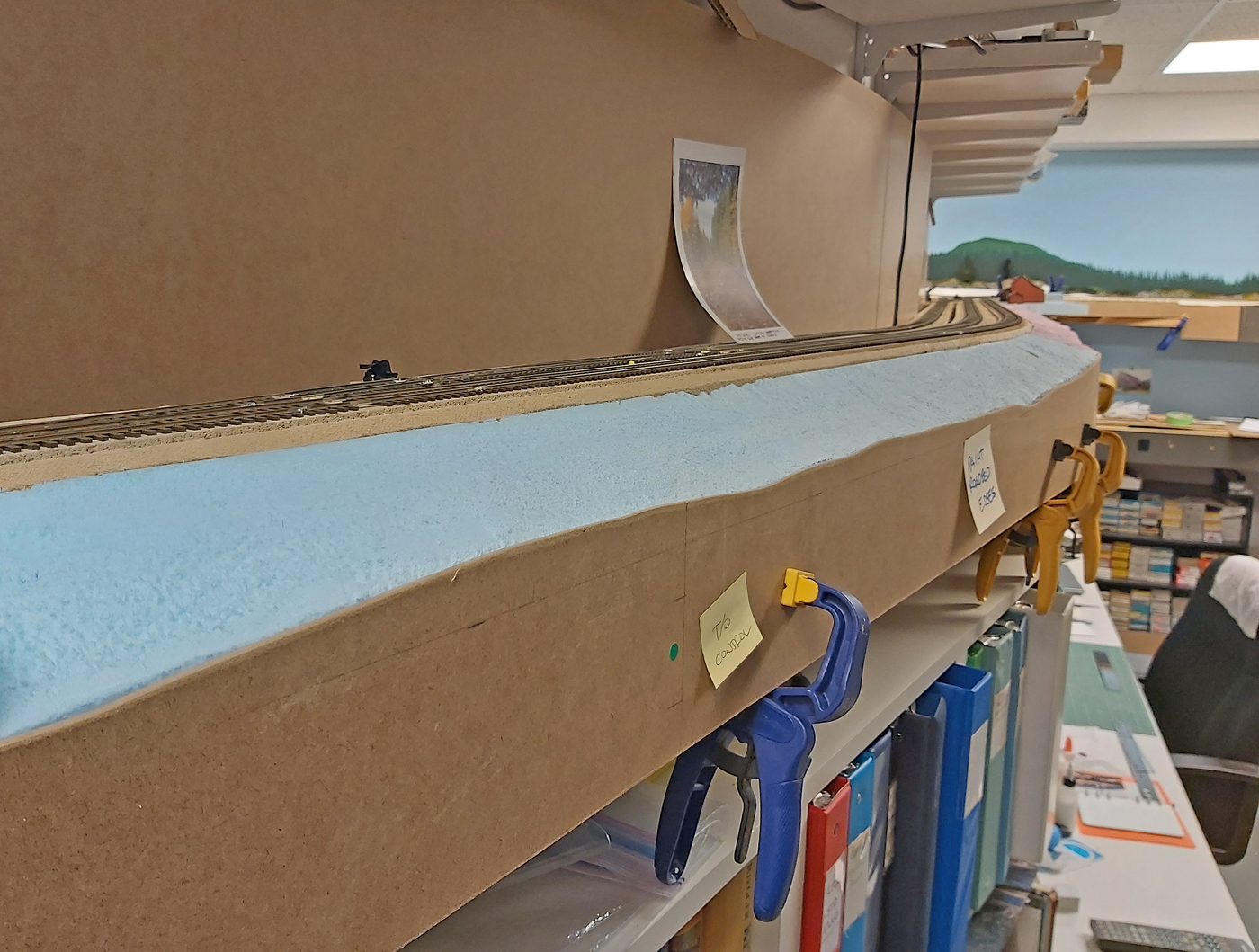
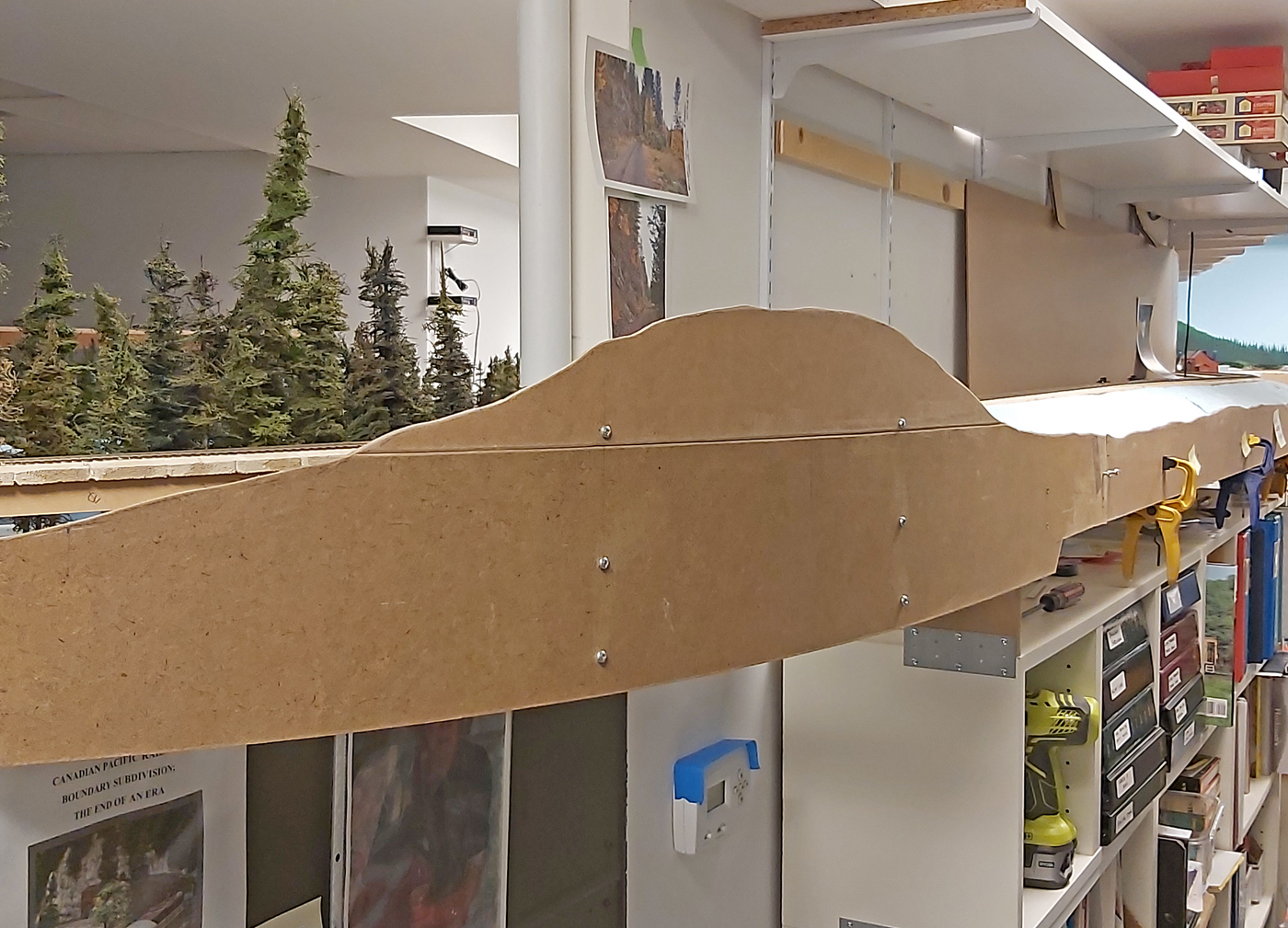
Here we see the two shaped 4 foot long sections of landform shown in the two previous photos. The photograph leaning against the backdrop is a prototype scene I am using to guide my efforts.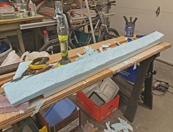
This is the completed landform as shown in the photo above.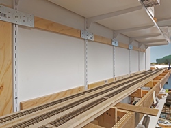
Looking west along the siding – with the landforms removed; this shows the wall strapping that is glued to the wall to allow the hardboard backdrop material to cover the metal shelf brackets. The metal plates are only holding the wood until the glue dried.

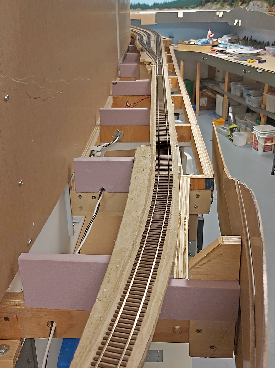
This photo provides a good view of the use of pink Styrofoam risers glued on top of the joists. The completed Styrofoam landforms will rest on top of these. There is no point installing any Styrofoam landforms below the roadbed if not needed, so these risers raise them up as required.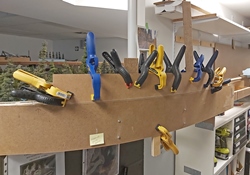
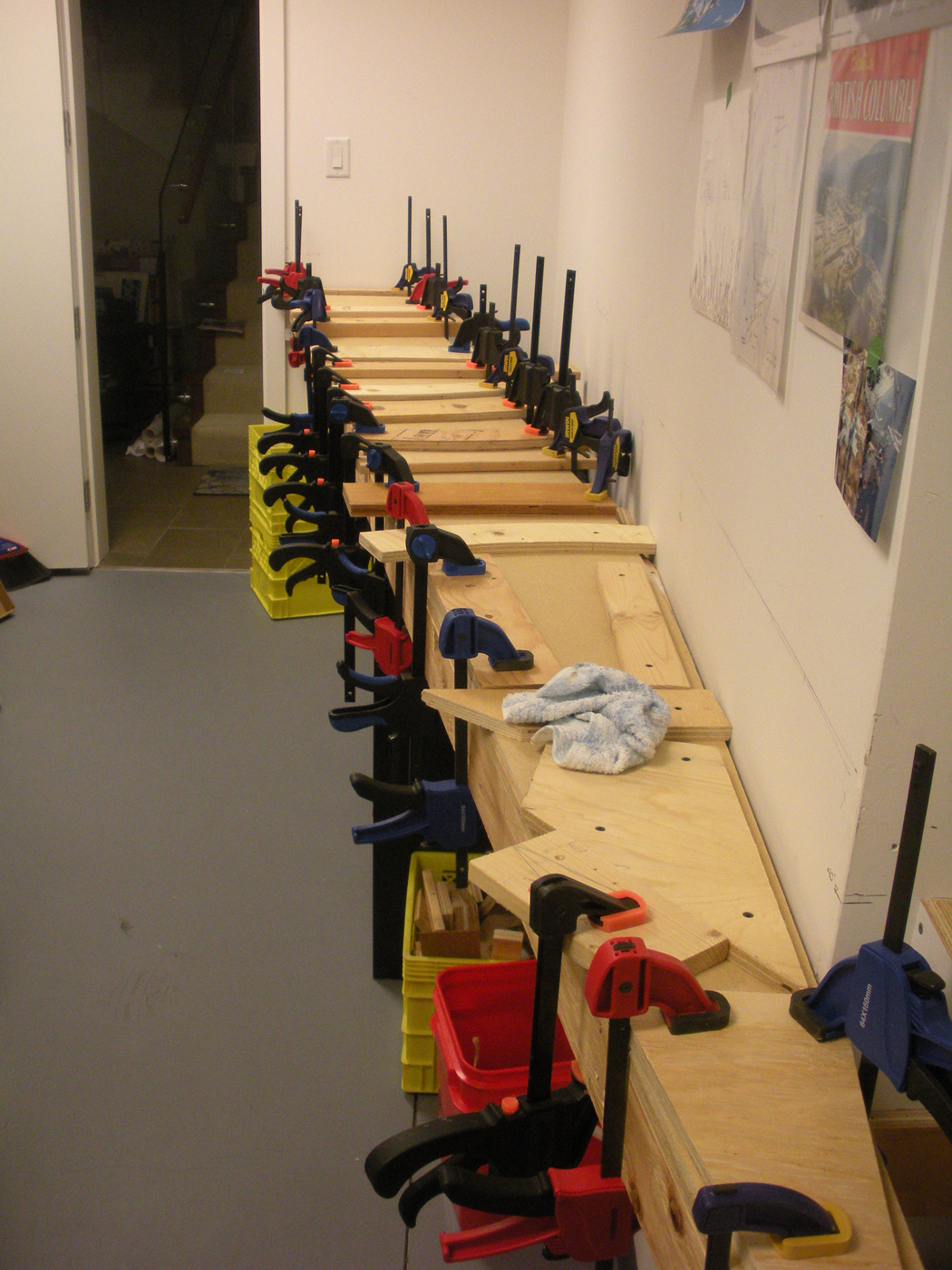
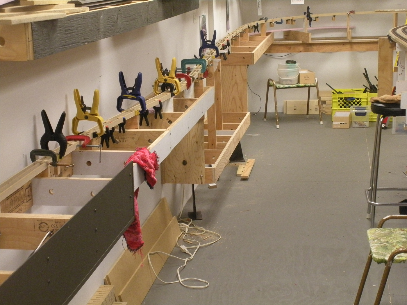
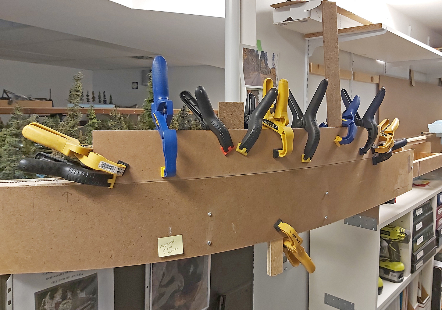
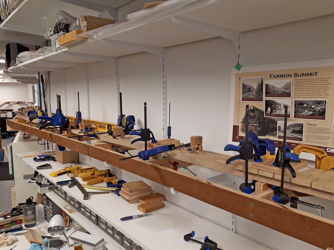
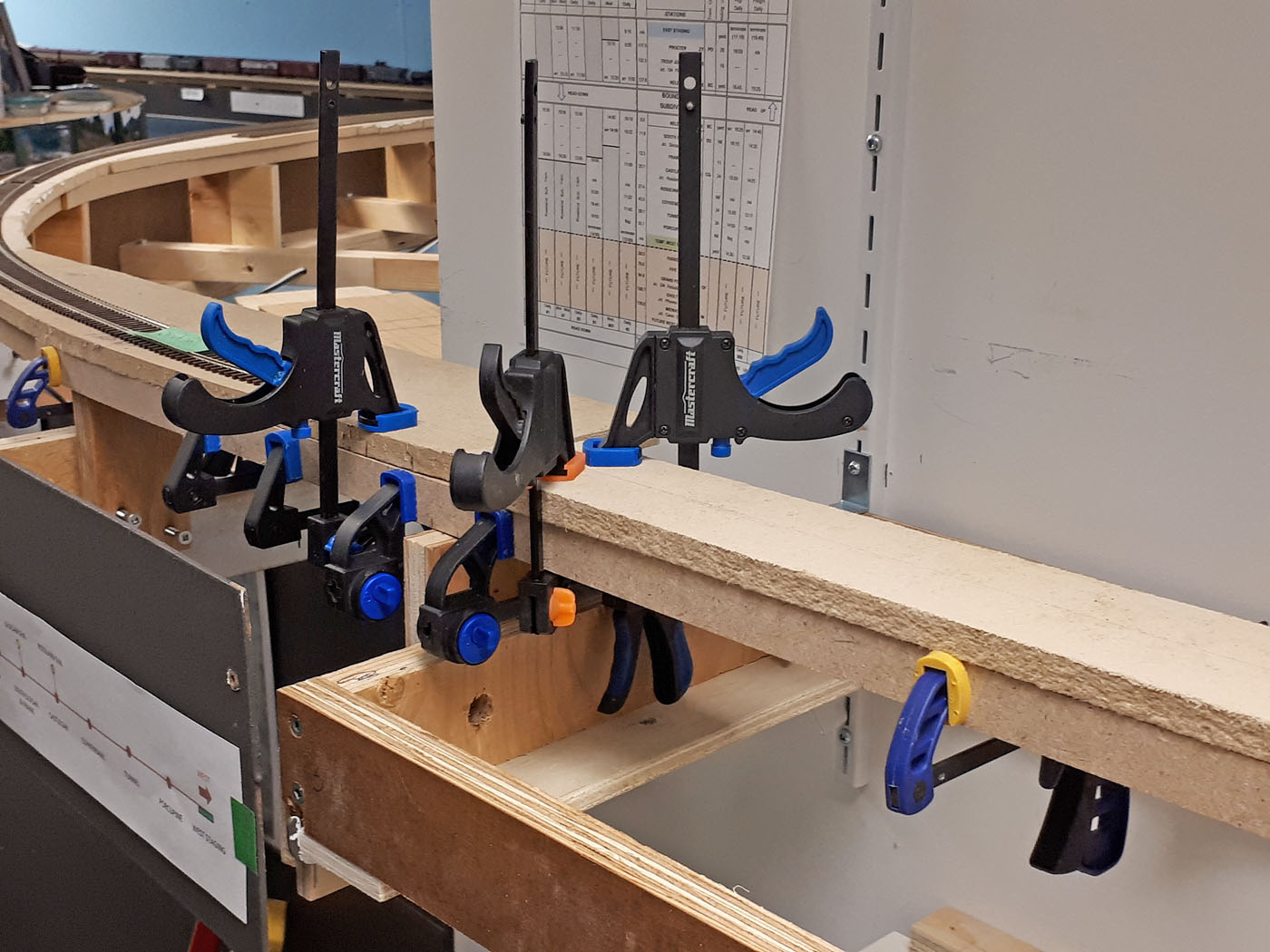
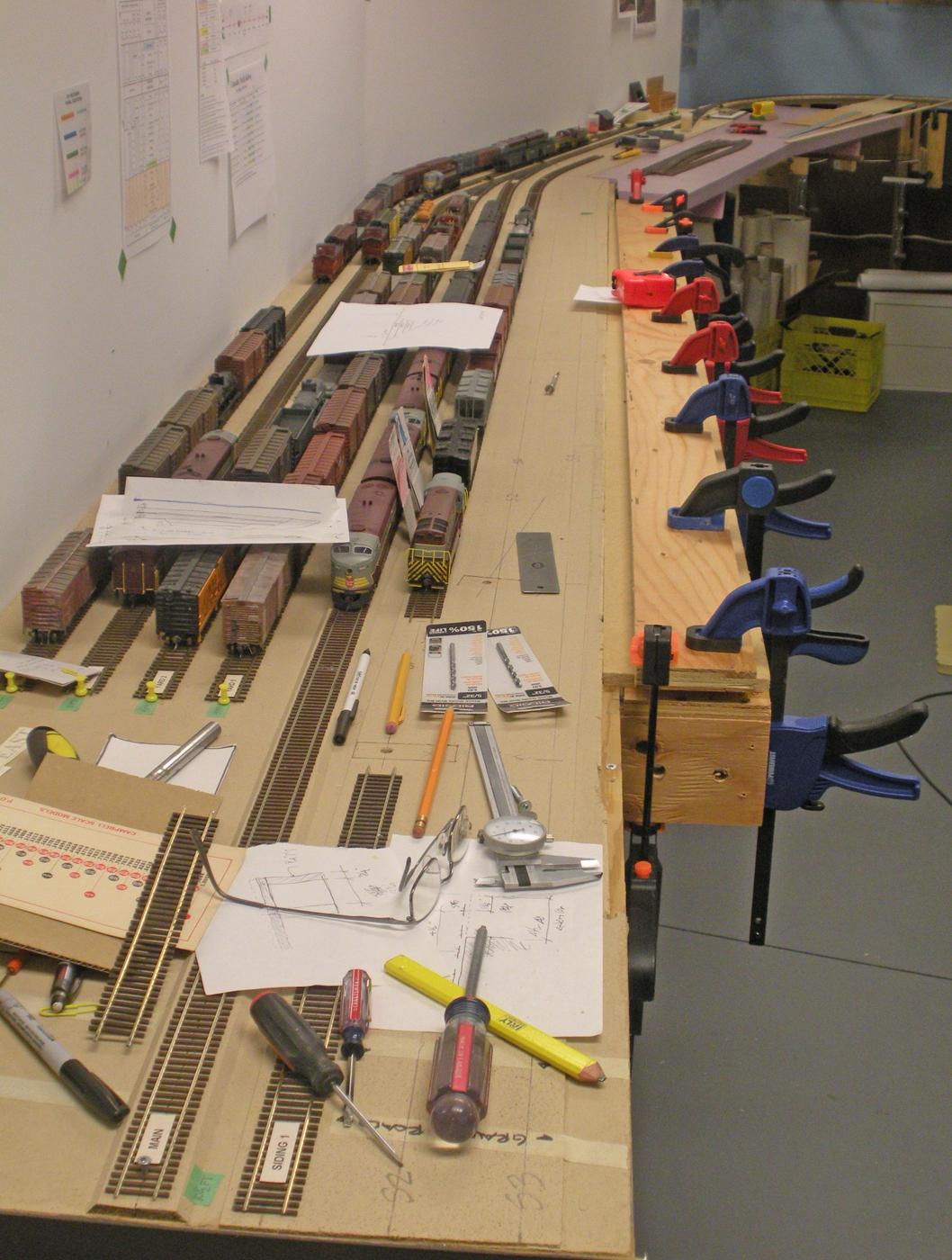
I decided to introduce a cut east of Farron as the curved track approaches the siding area to visually break up the scene. The higher scenery created by the cut necessitated extending the existing fascia to increase the height. This photo falls into the category; you can NEVER have enough clamps!
Shows the added section of hardboard with the clamps all removed.

Shows the added fascia cut to suit the topography I want to achieve.
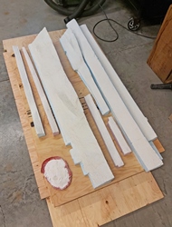
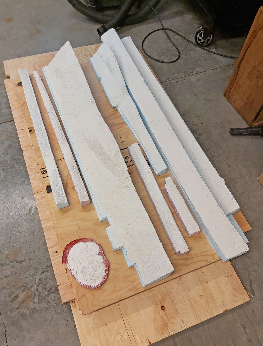
Here is a view of the new Farron landforms. In the lower left is a red rock mold filled with excess plaster. When coating the landforms with plaster, or doing rock castings, there is ALWAYS excess plaster, so we put it in molds and then crush and color the plaster later to create custom colored talus.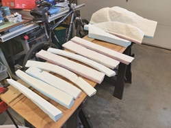
This is a view of the other batch of Farron landforms. In total 19 sections were required for this phase; from quite small to very substantial.
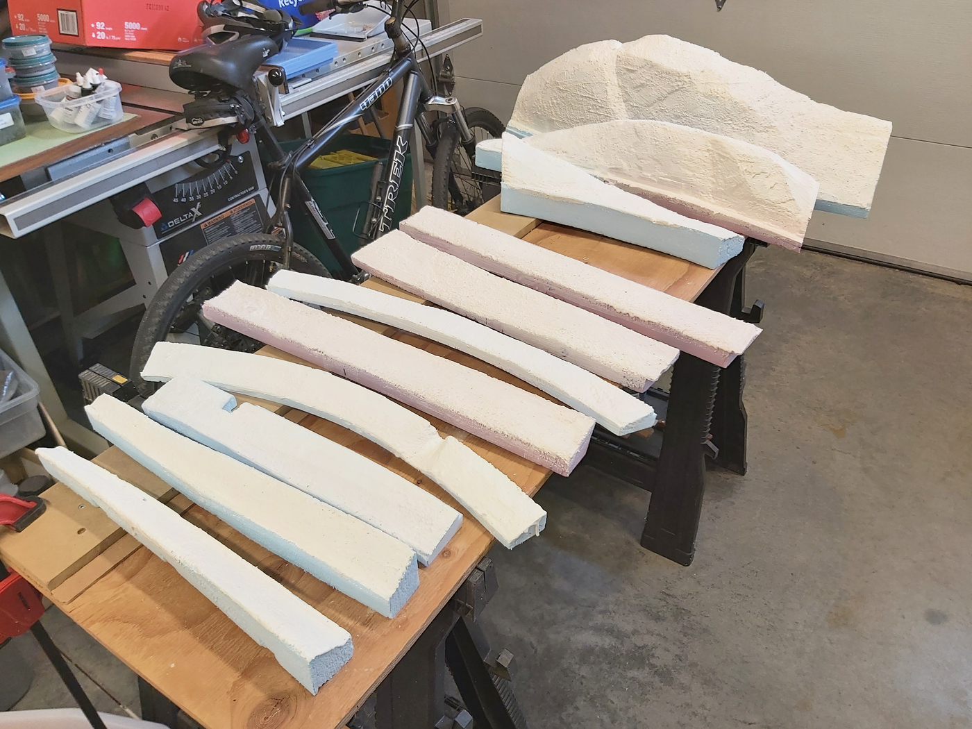
The foam blocks have been cut and glued together to form the basic land mass on both sides of the cut.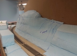
The foam blocks on the uphill side of the cut have been roughly carved and are being test fit. I write notes and draw lines on the foam with a blue Sharpie marker to record the necessary revisions and then return to the garage/shop to make the changes.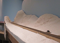
This is a current view looking through the cut. The landforms have received a base coat of plaster and all the rock castings. There were 8 different rock molds used to create this cut. This is now ready for the coloring and textures.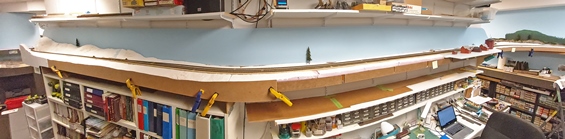
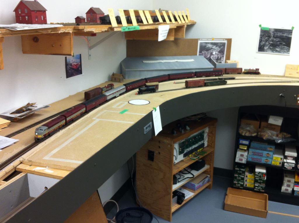
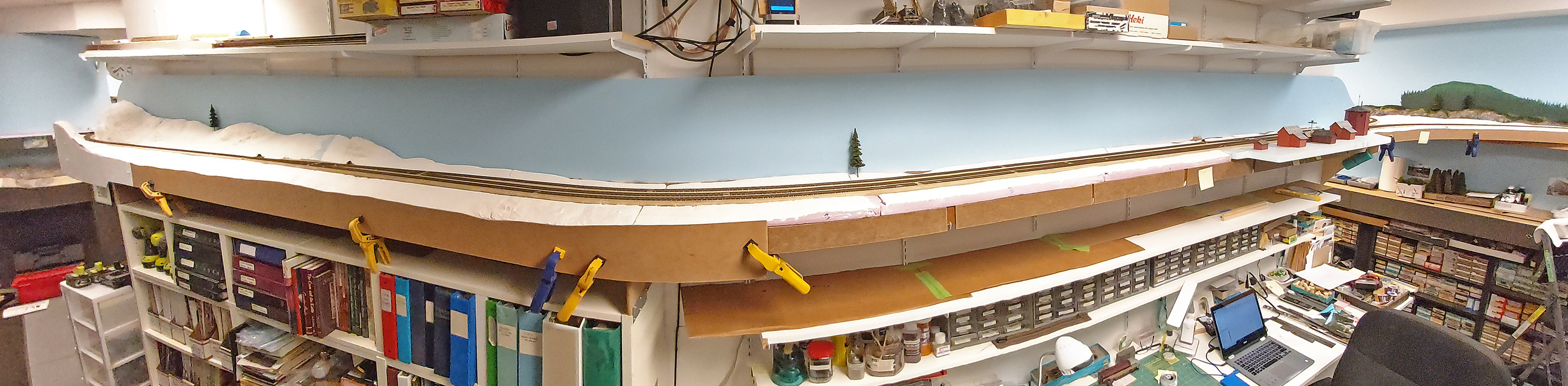
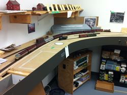
Preliminary panorama of the 30 foot stretch at Farron. East is to the left and west to the right. The wye can just be seen in the upper right hand corner – beyond the buildings. -
-
-
September 2019 Progress Photos
-
Here are a series of progress photos of the layout to date. Lots of work to do, however, these provides a sense of what our objectives are. They are just a sample of various scenes around the layout.
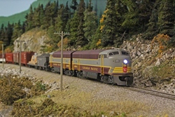
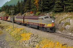
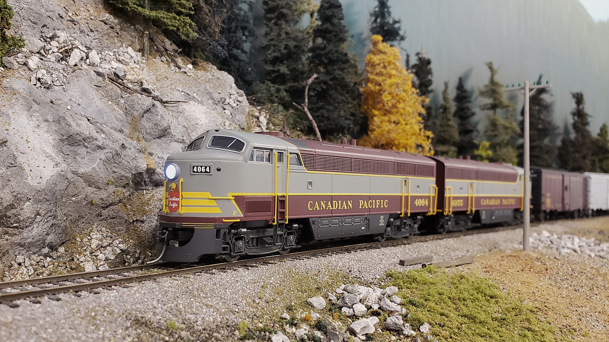
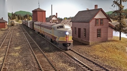
Extra 4104W holding the siding at the summit in Farron.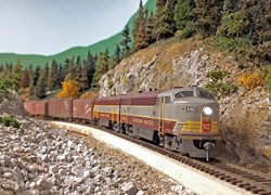
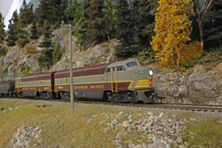
Extra 4104W passing through a rock cut just west of Farron.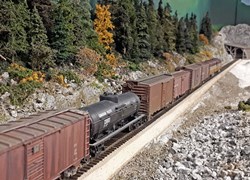
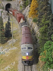
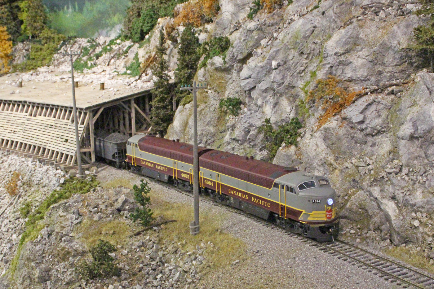
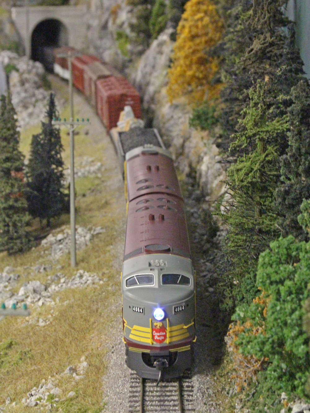
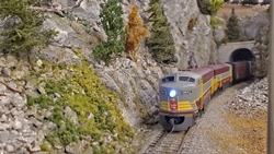
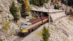
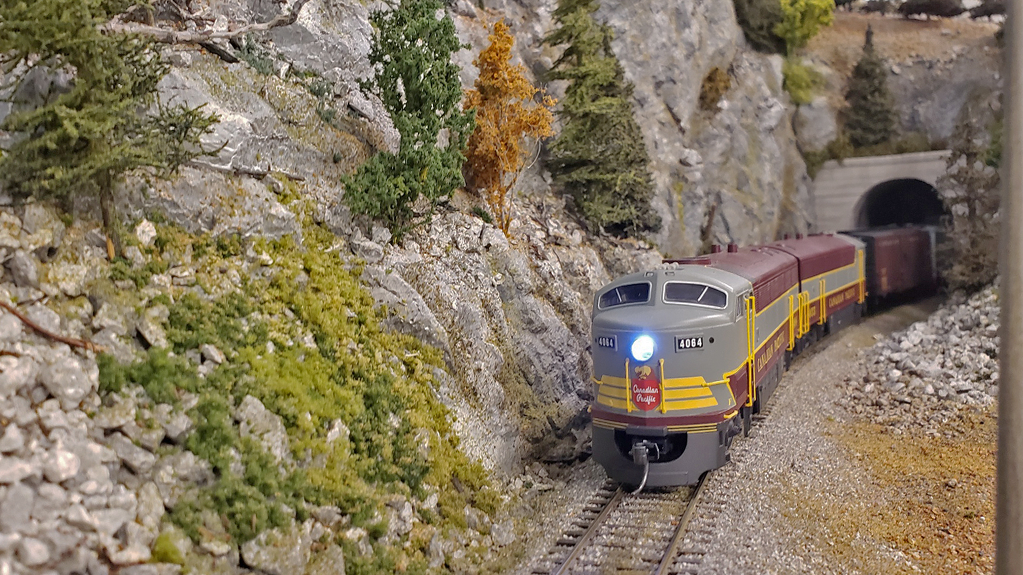
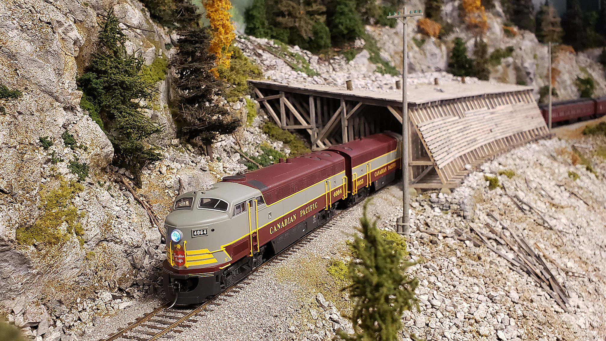
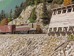
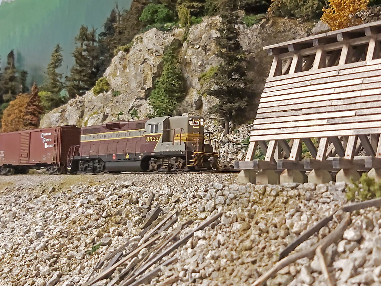
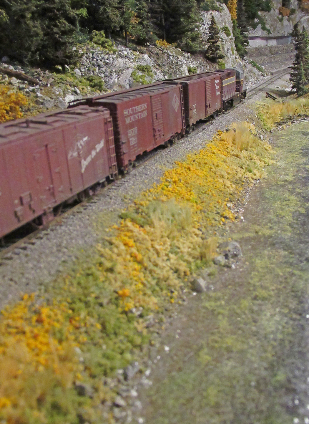
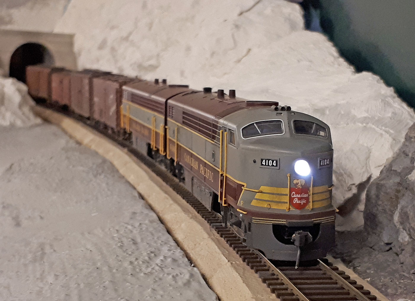
Extra 4104W drifting down the grade towards the Paulson snowshed.
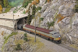
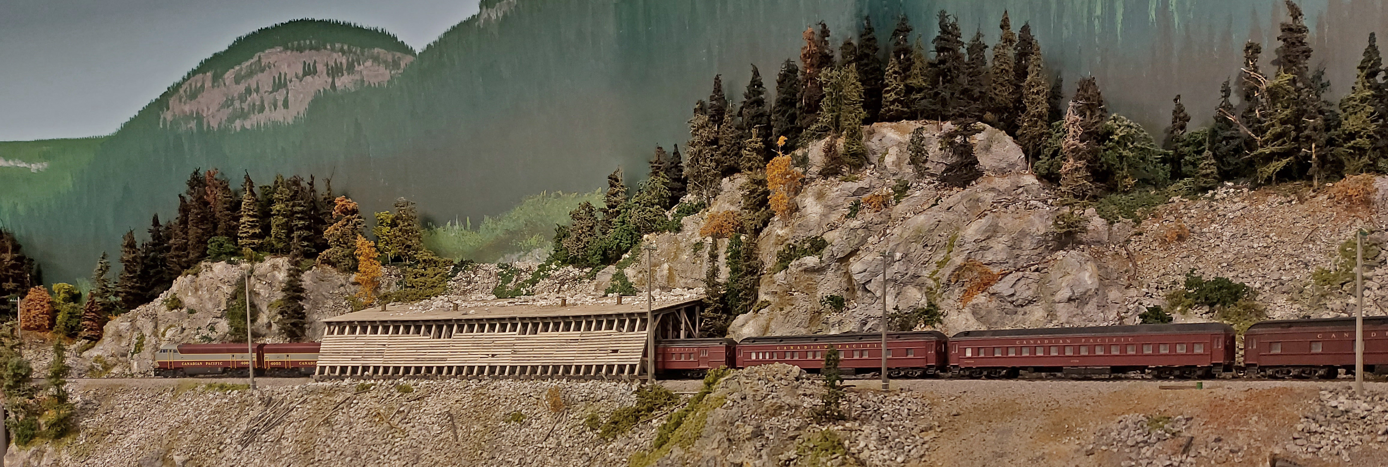
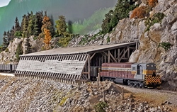
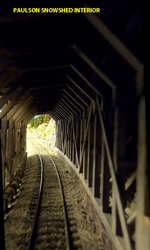
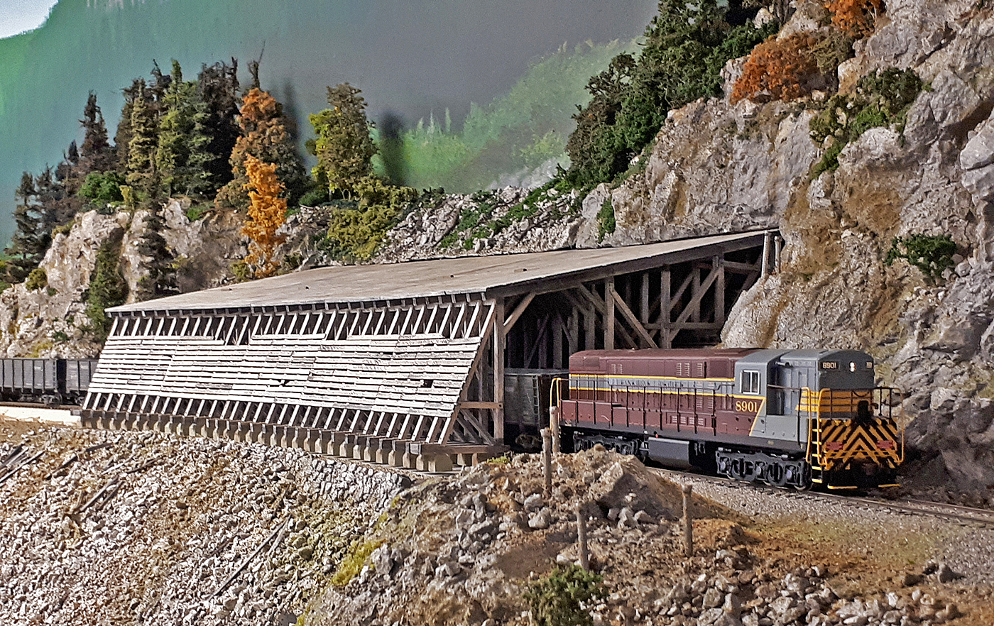
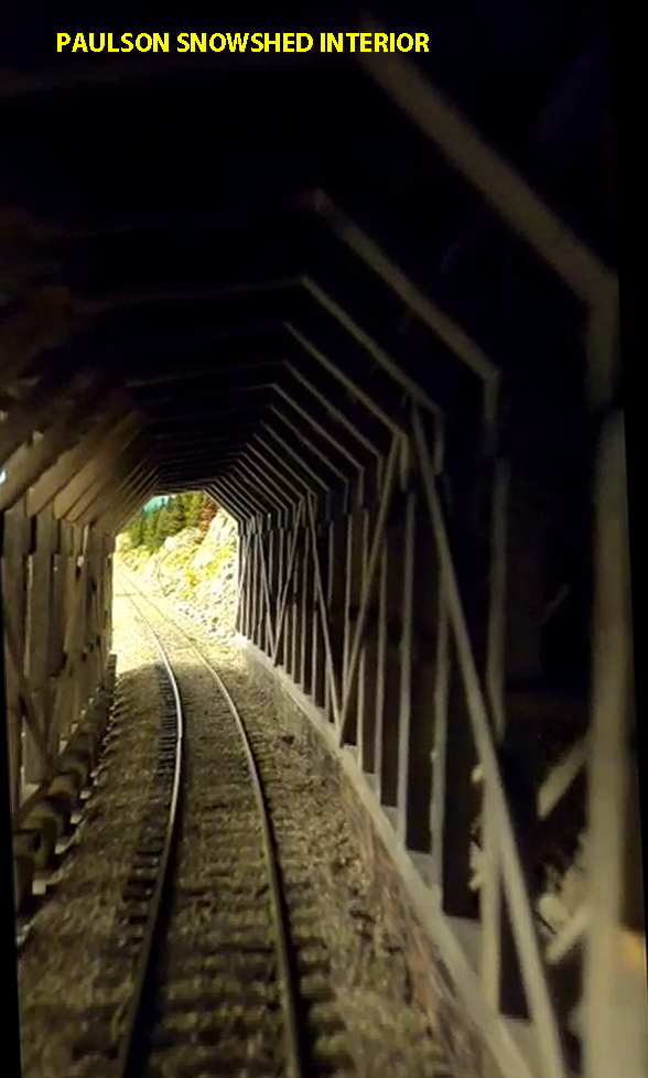
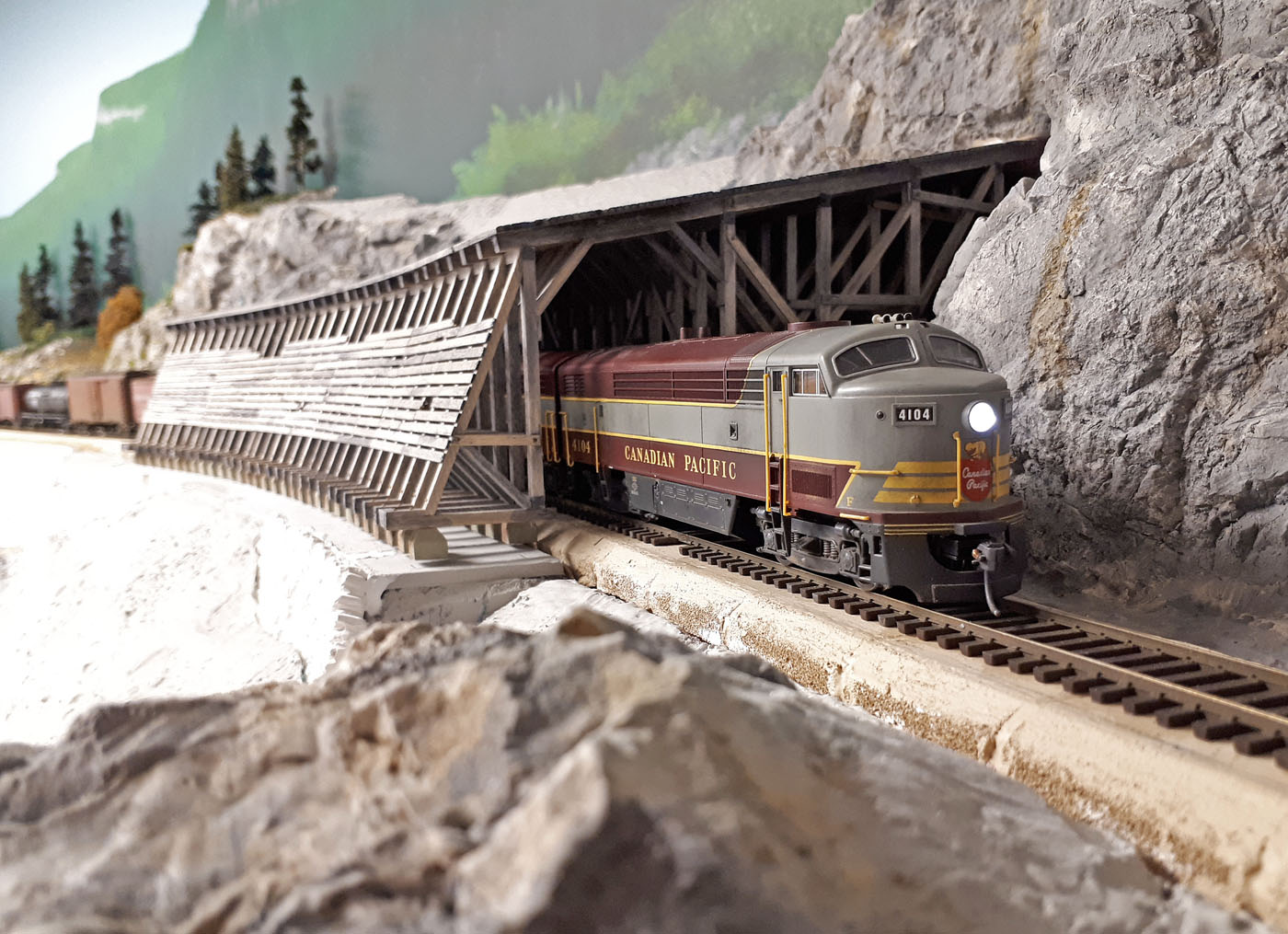
Extra 4104W running through the scratchbuilt snowshed at Paulson.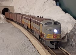
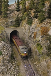
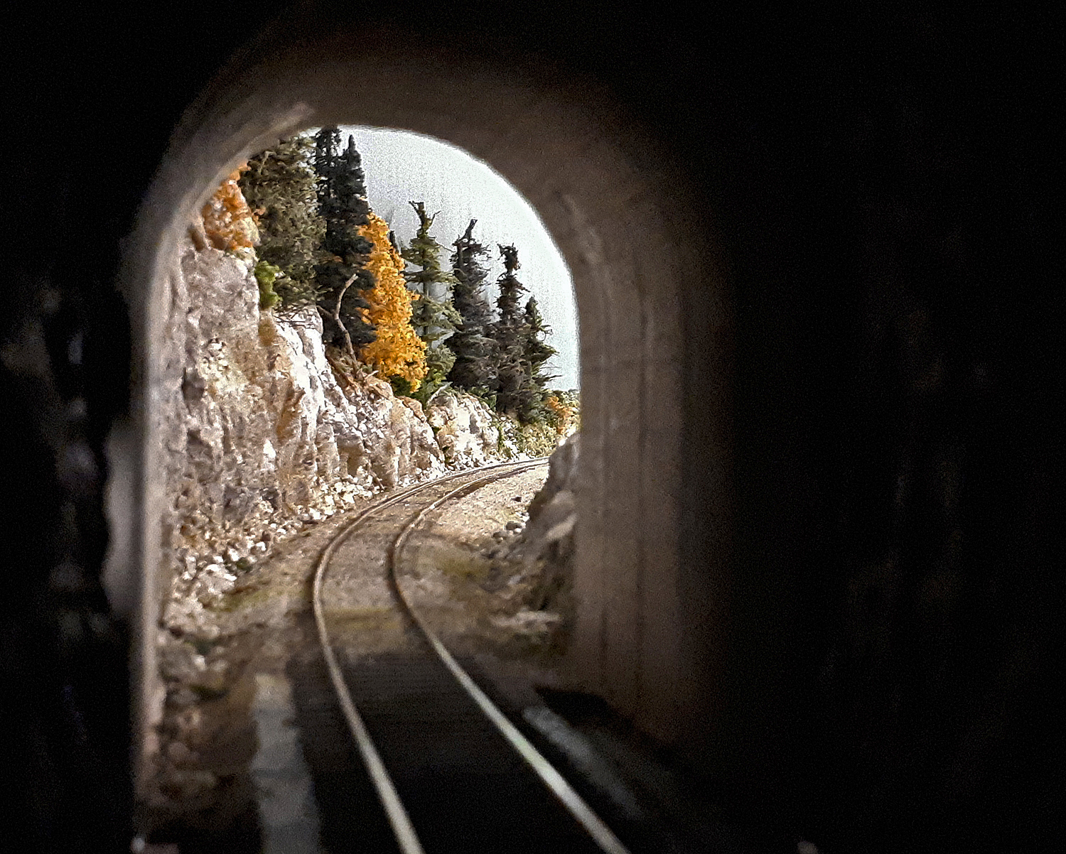
Extra 4104W emerging from the west portal of the Paulson tunnel.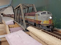
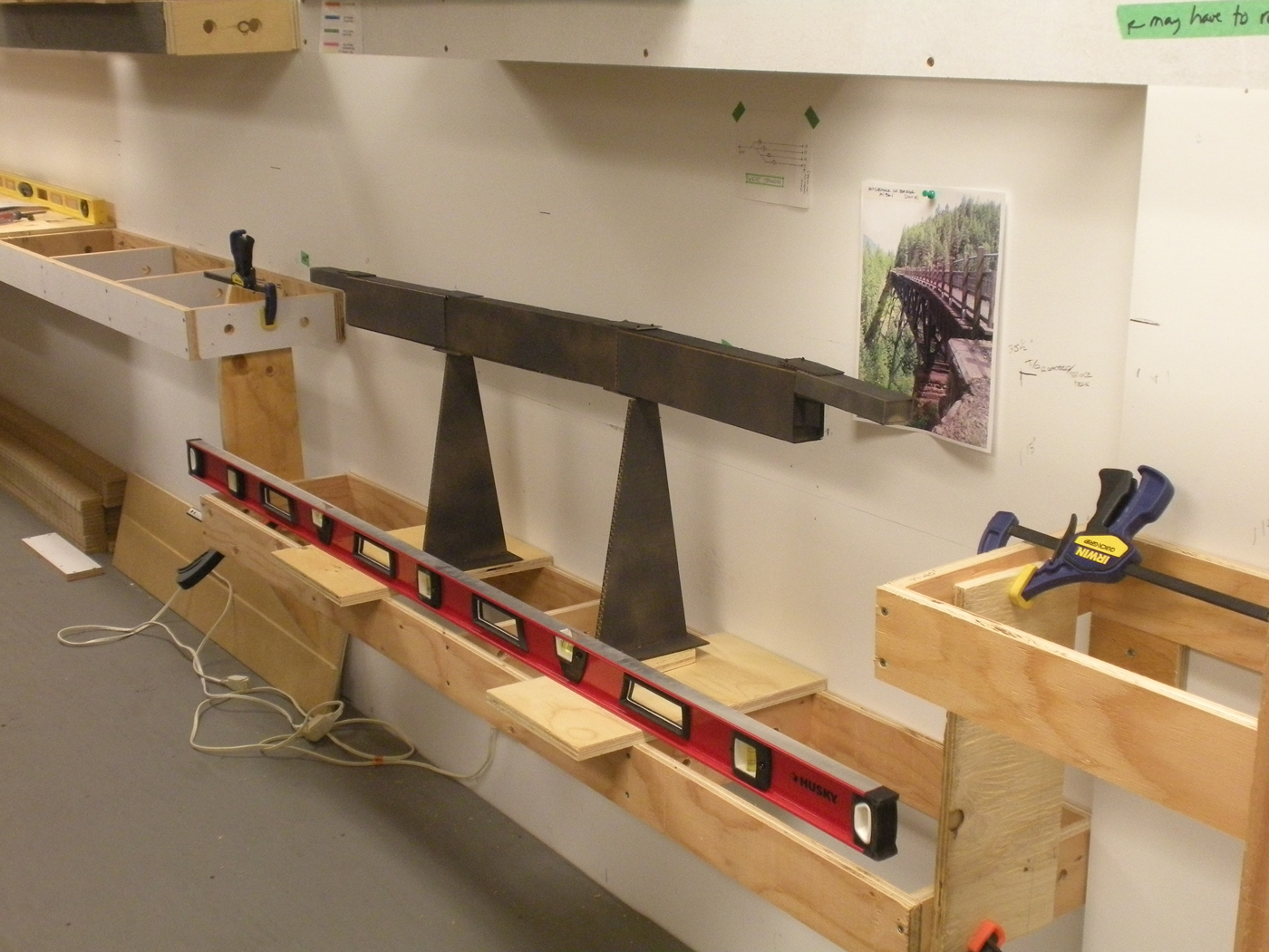
Extra 4104W crossing the bridge over Slide Creek in a mocked up scene.
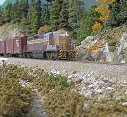
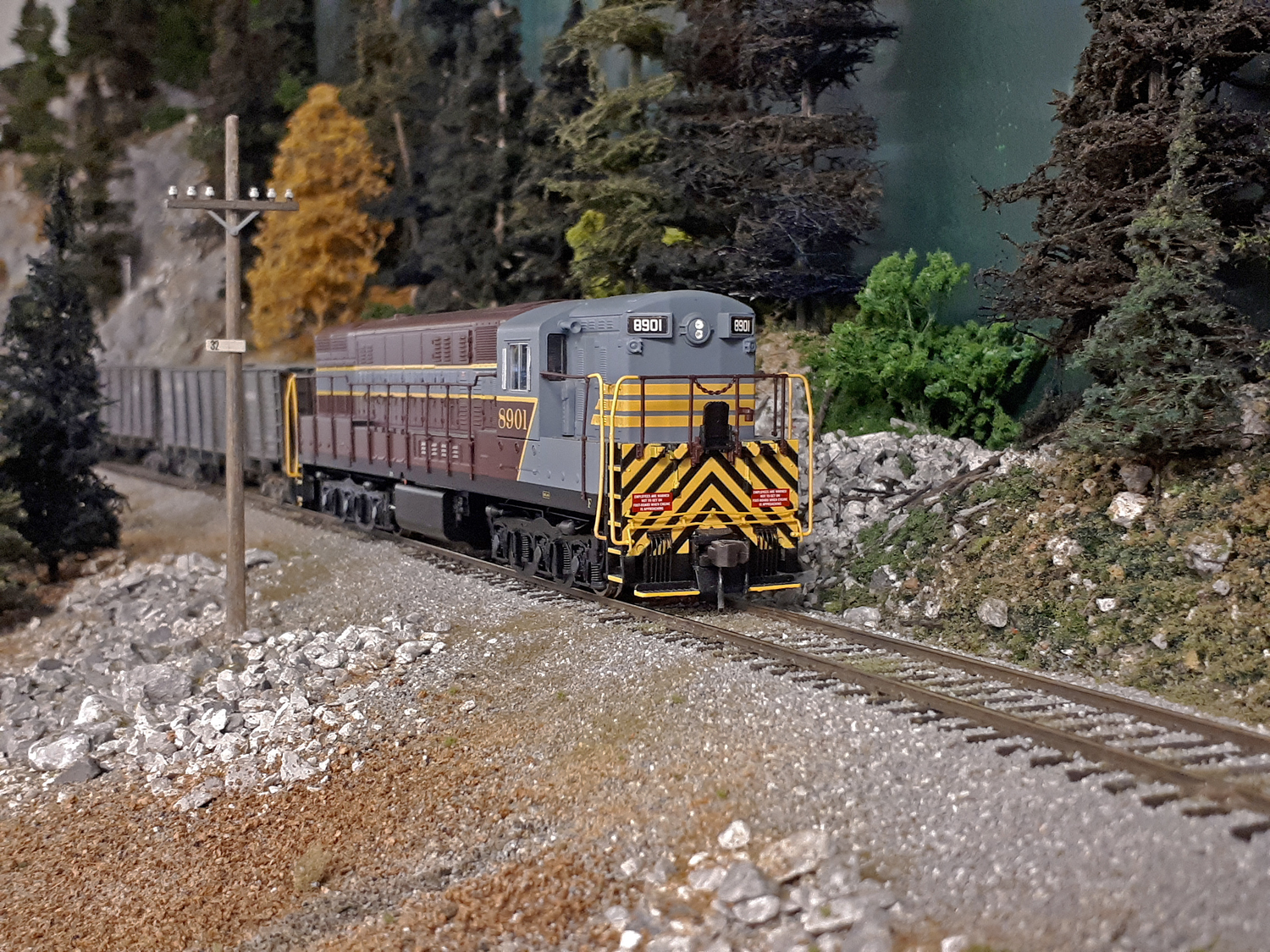
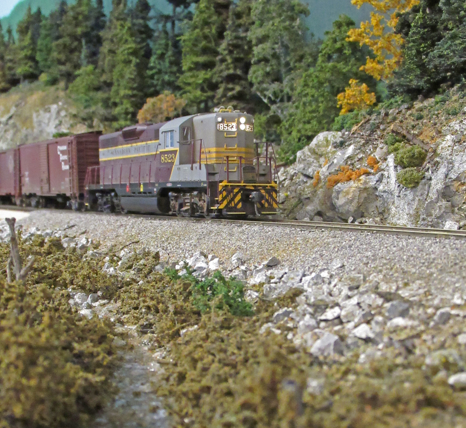
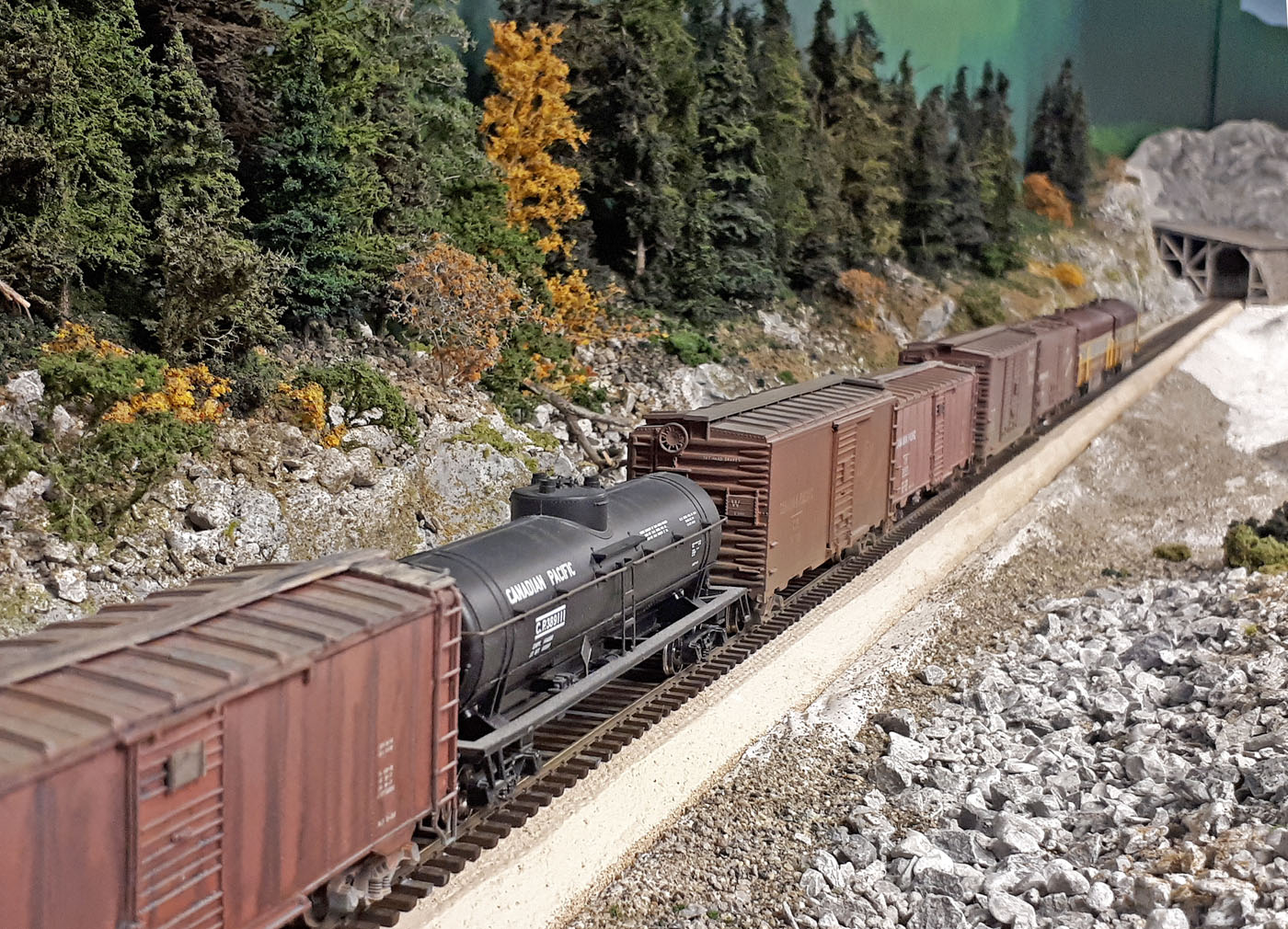
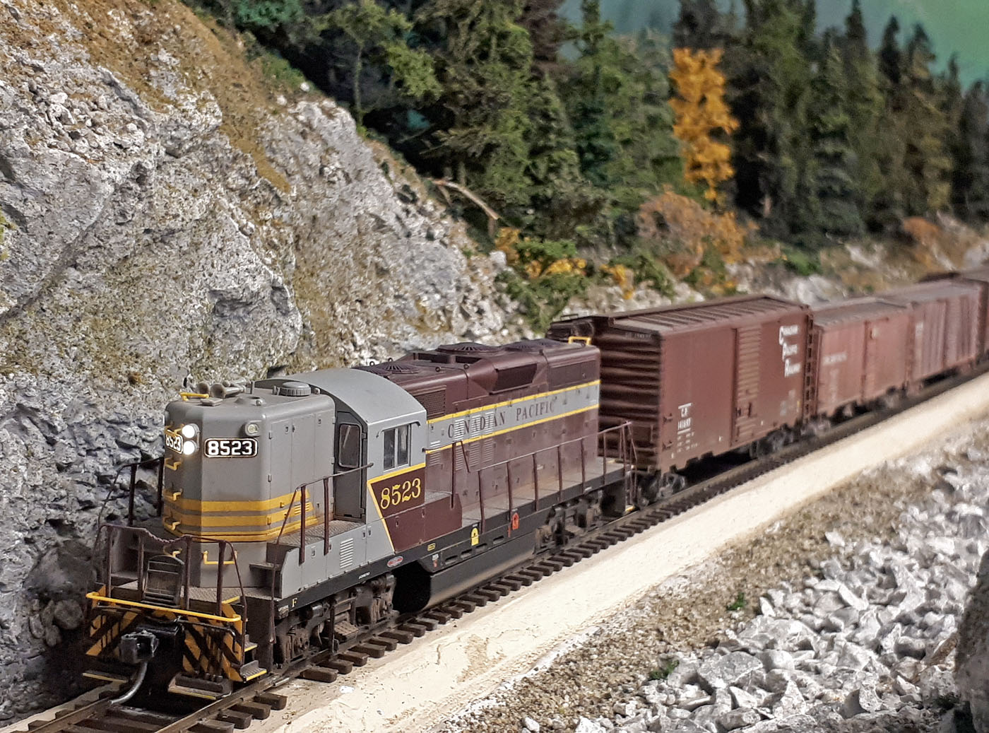
Extra 8523E way freight approaching the west limit of Farron.
Eastward through freight #968 holding the siding in Farron.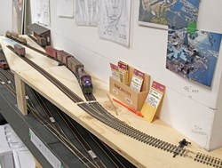
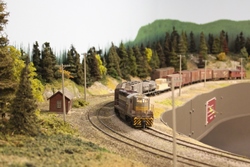
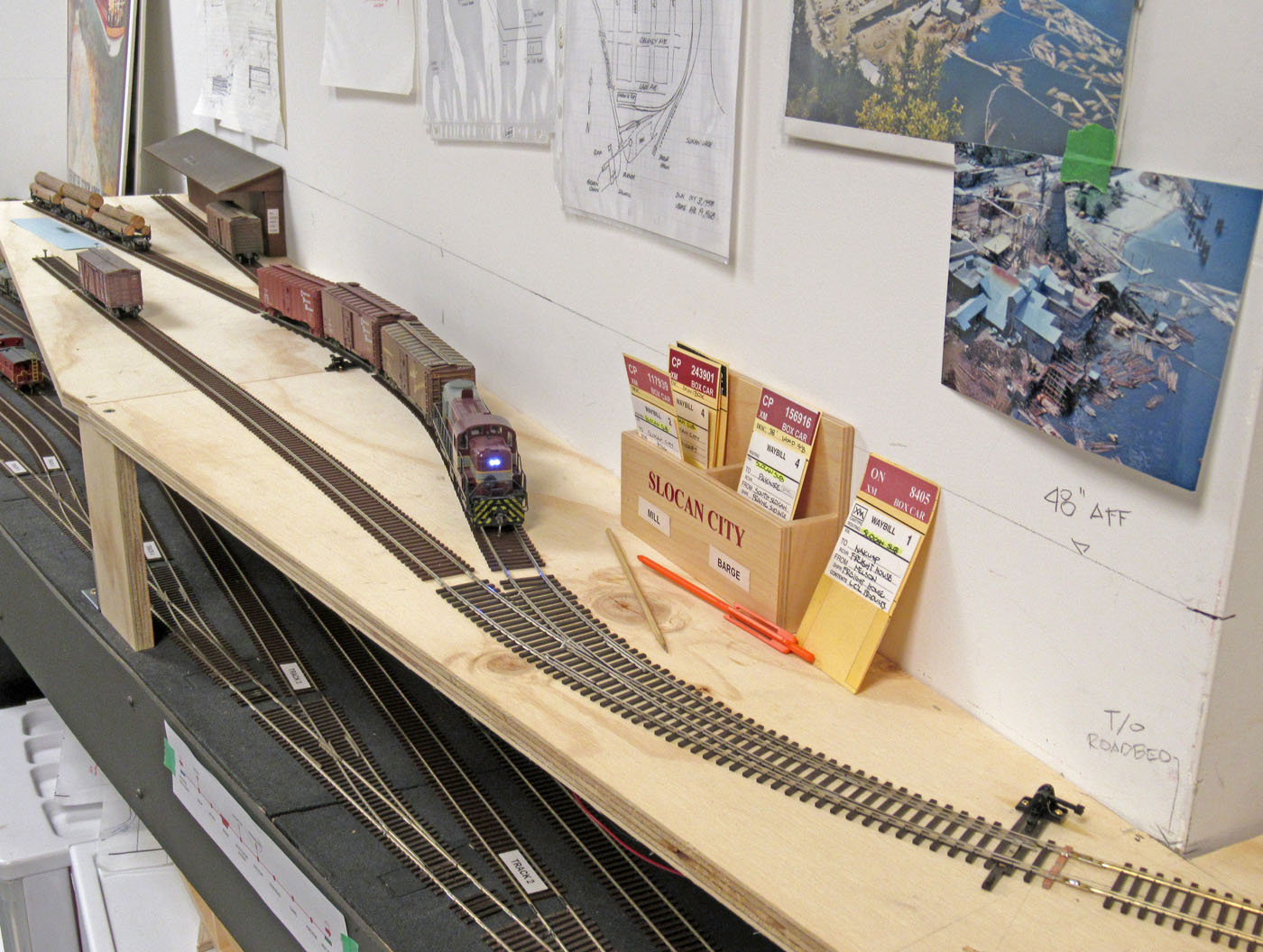
The Slocan Turn local switching industries in the temporary Slocan City area.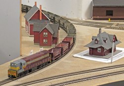
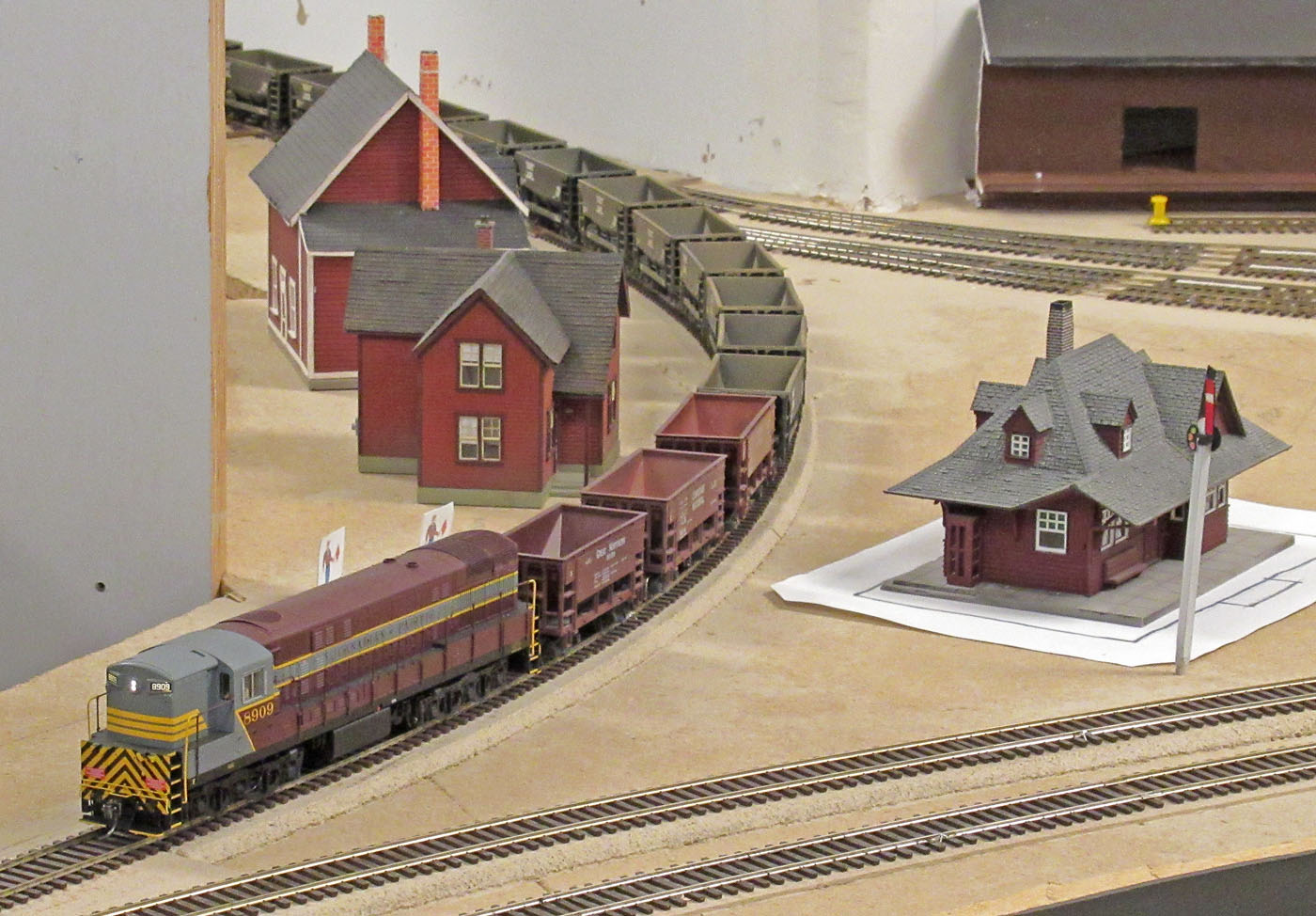
Eastward empty ore train extra 8909 holding on the wye at Castlegar for clearance and orders to proceed to Nelson.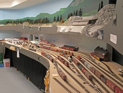
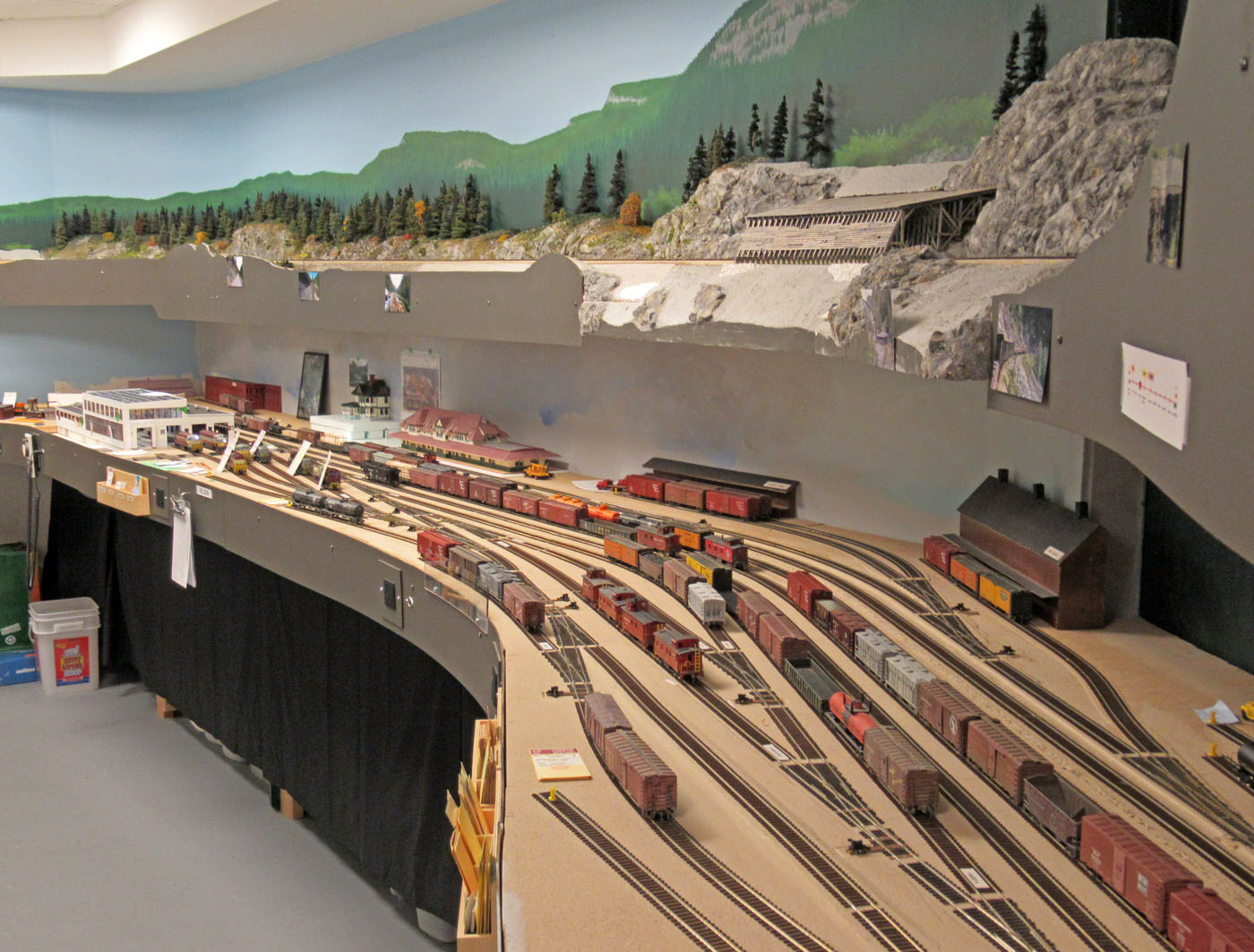
Overall birds eye view of the current state of the divisional yard at Nelson.

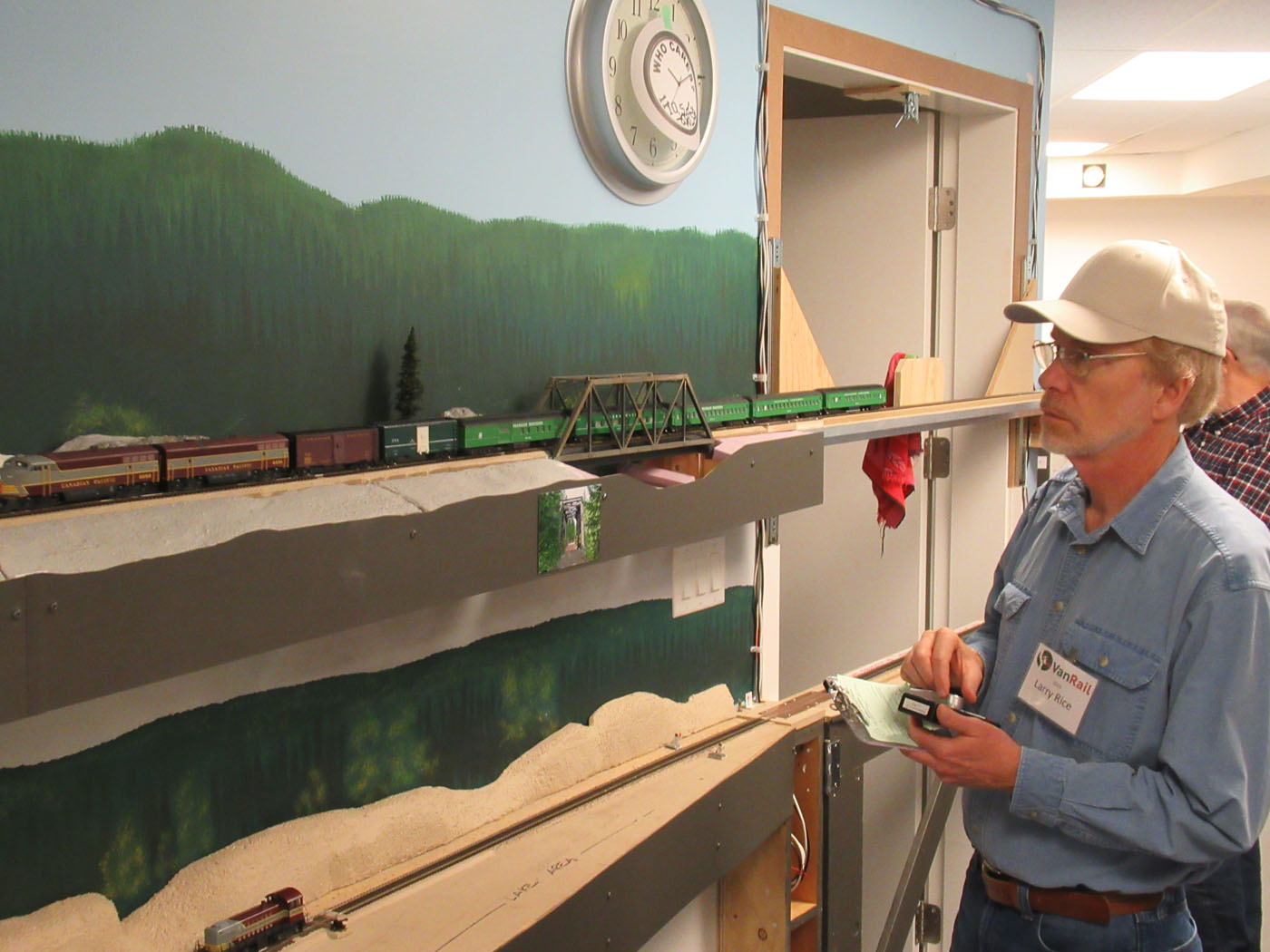
Eastward passenger train #46 has just crossed the lift up bridge over the room entry and has passed through the Slide Creek bridge and is approaching the west portal of the Paulson tunnel.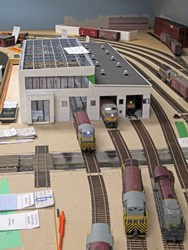
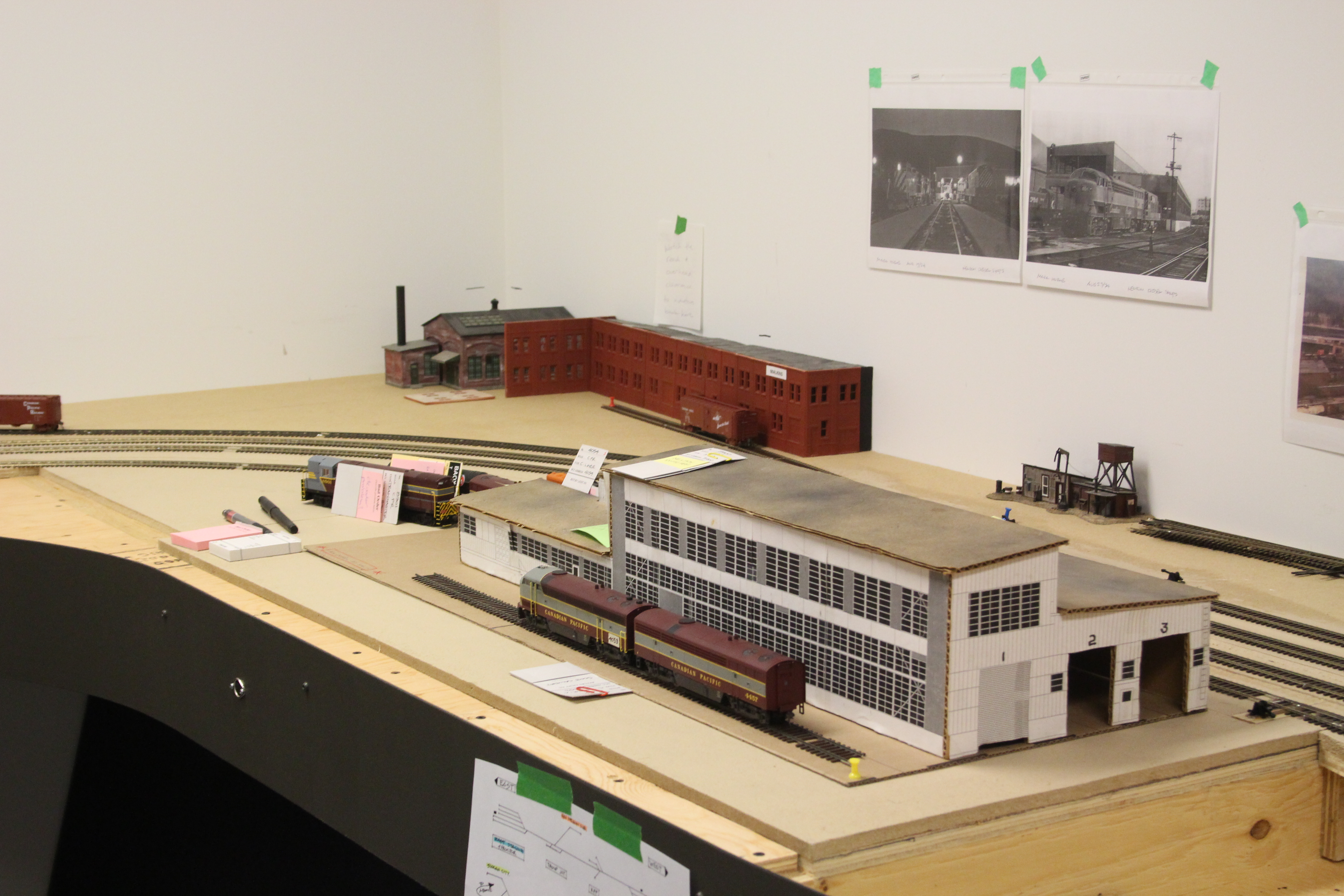
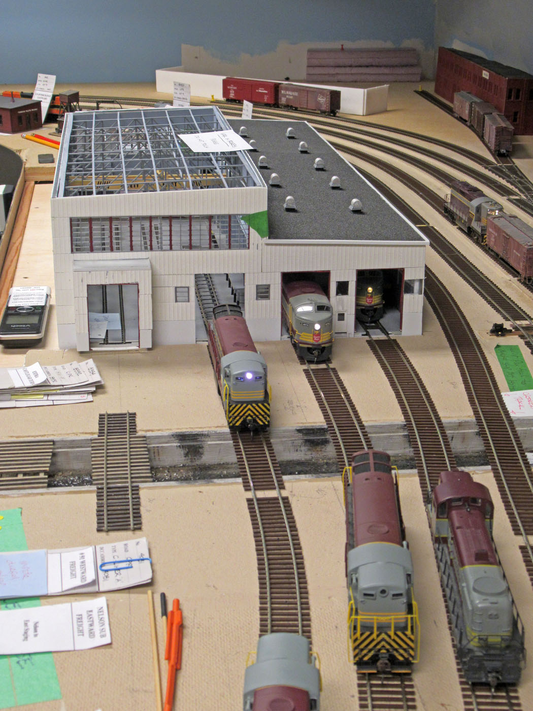
A variety of locomotives at the Nelson diesel shops. The building and surrounding area are still works in progress.
-
-
Summer 2019; Upper Deck Scenery Continues
-
Work on the upper deck scenery commenced in the fall of 2018 once the framing concept had been finalized for the cantilevered modules that would support this next phase of the layout. As reported elsewhere, we elected to build the scenery using Styrofoam landforms over which we applied a base coat of plaster with rock castings where appropriate, and then a variety of scenic textures and materials.
This process was interrupted twice to accommodate hosting operating sessions for RMMBC in May 2019 and VanRail in September 2019 when the layout was restaged to accommodate these sessions. In late September, we once again decommissioned the layout so we could continue towards the completion of the scenery for this part of the layout. As of the writing of this post, it is our intention to complete the scenery before recommissioning the layout for further operations. This is anticipated to occur in early 2020.
It has been a time consuming and iterative process to advance the scenery along for this phase with a lot of trial and error and relearning of scenery skills. There was also a lot of research that went into this phase because we are trying to emulate specific scenes on the prototype rather than creating generic scenery.
The construction of this upper deck now creates shadows on the lower Nelson yard area, and we are now in the early stages of researching lighting solutions to install under the upper deck. This will be the first section of the layout to receive this lighting so we want to get it “right”. There is approximately 300 feet of upper deck that will need lighting installed below it.
A great deal of effort has been invested in this work by my home crew; Ken C, John M, Bill D, and Rene G. without their help, the progress would not be where it is so far. We are pleased with the outcome and feel that the scenery is looking very realistic.
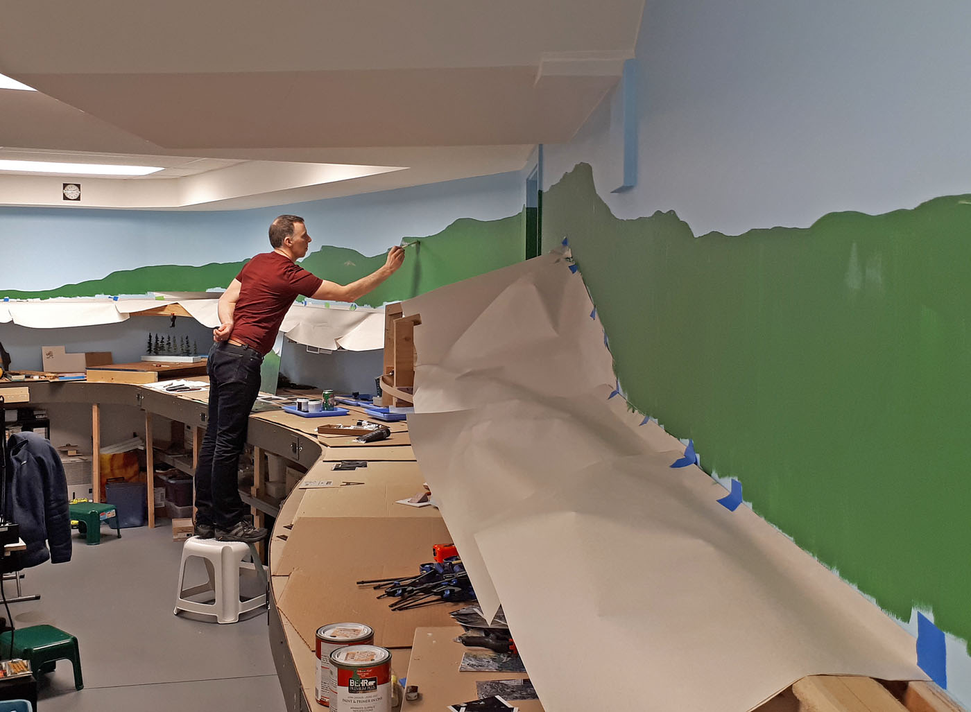
Here is a variety of photos of the work:
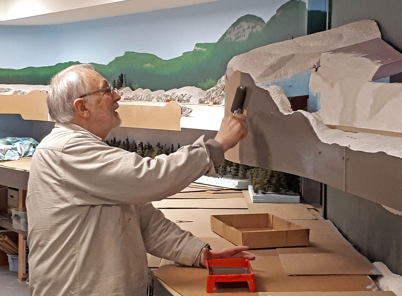
The preparation for the actual backdrop painting included painting some sample hardboard panels to test colors, assembly of some of the trees we would be using, and gathering photographs to guide the process.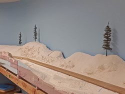
Here is a close up photo of the Styrofoam landforms in place. You can see the plaster base coat and several rock castings on these.
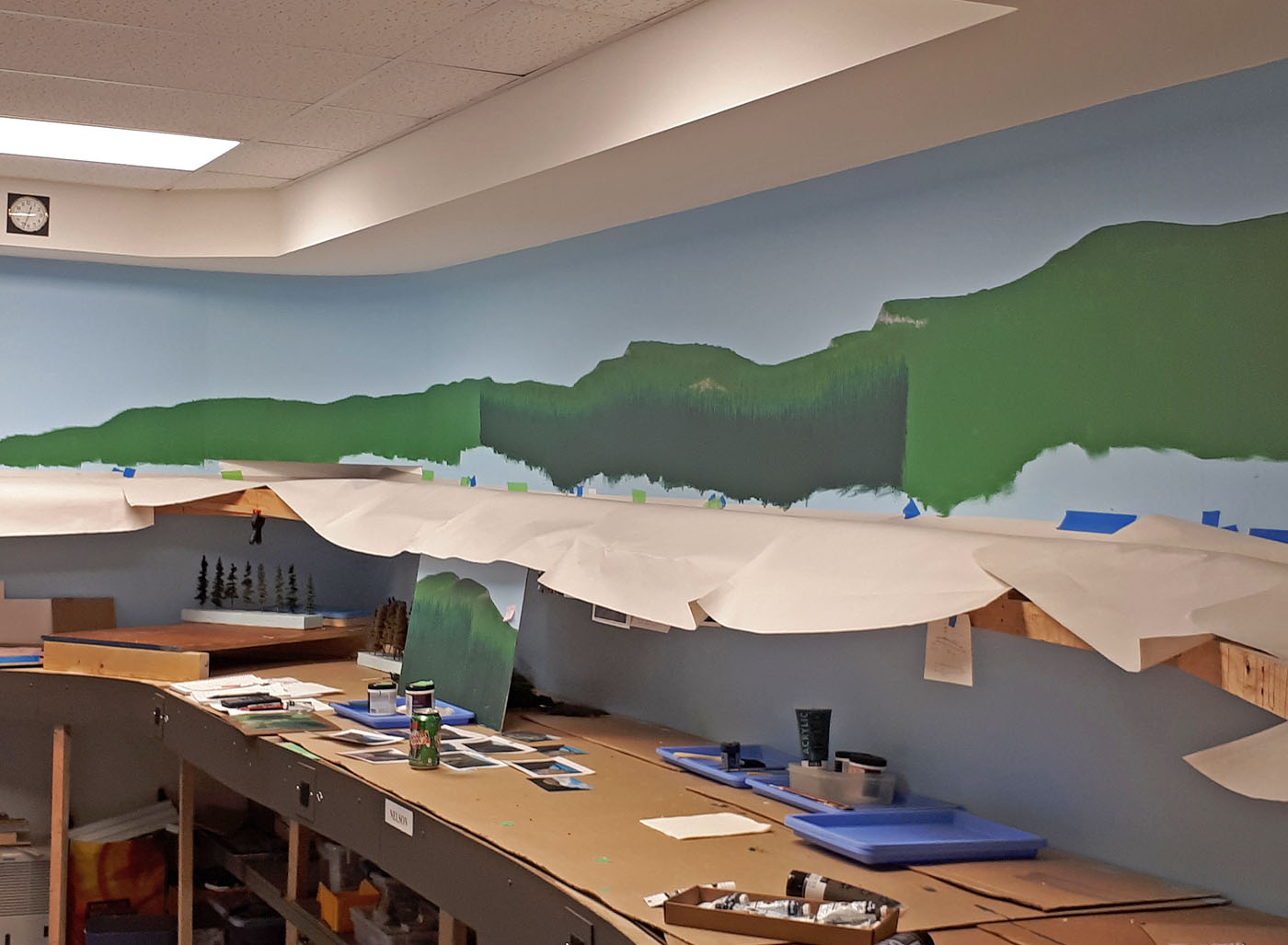
Here we see Rene G completing the backdrop base coat of green over about 35 feet of wall. The profile of the green was developed with the scenery landforms in position. Nelson yard is underneath all that protective cardboard!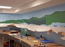
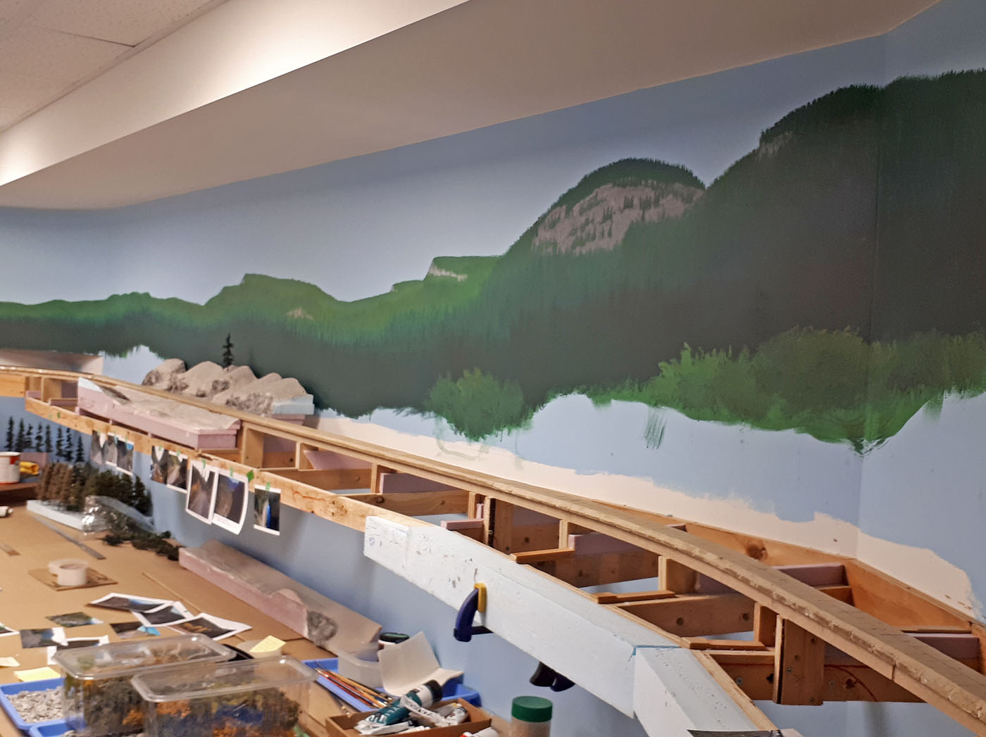
With the base coat completed, Rene then worked in sections adding the various color textures to create the look of a forested mountainside.
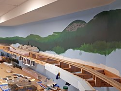
The detailed painting continued with colors that capture the dark depth of these forests. We tested the look with scenery landforms and trees as the work progresses.
This is a photo of a couple of landforms in place. These have all the basic scenic materials on them, and the trees and interface with the roadbed will be completed in place.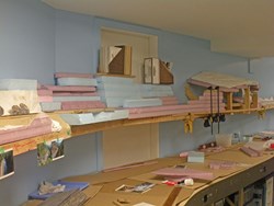
This photo shows how the Styrofoam layers are being assembled to create the scenery landforms. This stretch is between the Paulson snowshed and east tunnel portal.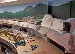
An overall view of the Paulson snowshed site coming together. Here we elected to bring the Styrofoam landforms down below the fascia height to create more slope below the shed.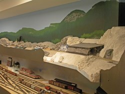
Here is the same scene with the fascias in place on either side of the slope.
Covering the Nelson yard provided a large surface to assemble the foliage and trees for the upper deck. Tree planting is well advanced on the landforms in the distance, and progress is heading towards the snowshed site.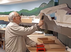
Here John M – our resident painter – is giving the fascias a coat of the standard battleship grey paint. All the fascias on this upper deck were installed to be removable to give flexibility as the scenery work continued.
This is a cut just west of the Farron siding. While the landform module is essentially complete, it still has to be scenically integrated into the layout and the track roadbed area needs to be completed.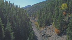
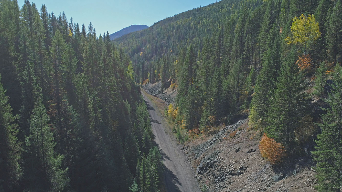
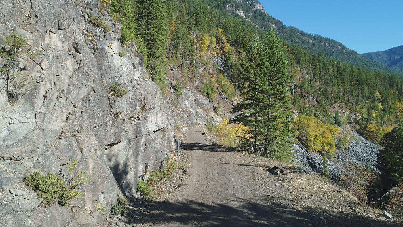
This is one of the drone photos taken in Oct 2017. The view is looking RR west from a location just west of Farron.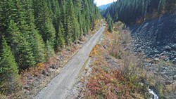
Another drone photo from Oct 2017 of the RR grade looking west towards Paulson.

This drone photo is taken looking west from the west portal of the Paulson RR tunnel.
-
-
Summer 2019; Phase 3 Mainline Completion
-
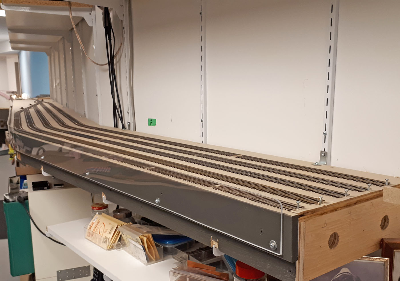
The After hosting operating sessions for RMMBC 2019 in May this year, we shut the layout down again and resumed work on the upper deck mainline extension with the objective of having it functional by VanRail 2019 in early September. We built as much of the framing and spline system as possible, and then dismantled, modified and reinstalled the 12 ft long temporary west staging yard in the next location for it.
Once the temporary staging yard was removed, we infilled its location with several prebuilt plywood framed modules. This allowed us to connect the end of the existing mainline with the other new modules that had been installed over the Nelson yard to date. Once that was completed, the spline roadbed system was installed and prepared for the trackwork. This work included the use of cork to create a slightly higher mainline. The phase of work used the same methods used throughout the layout.
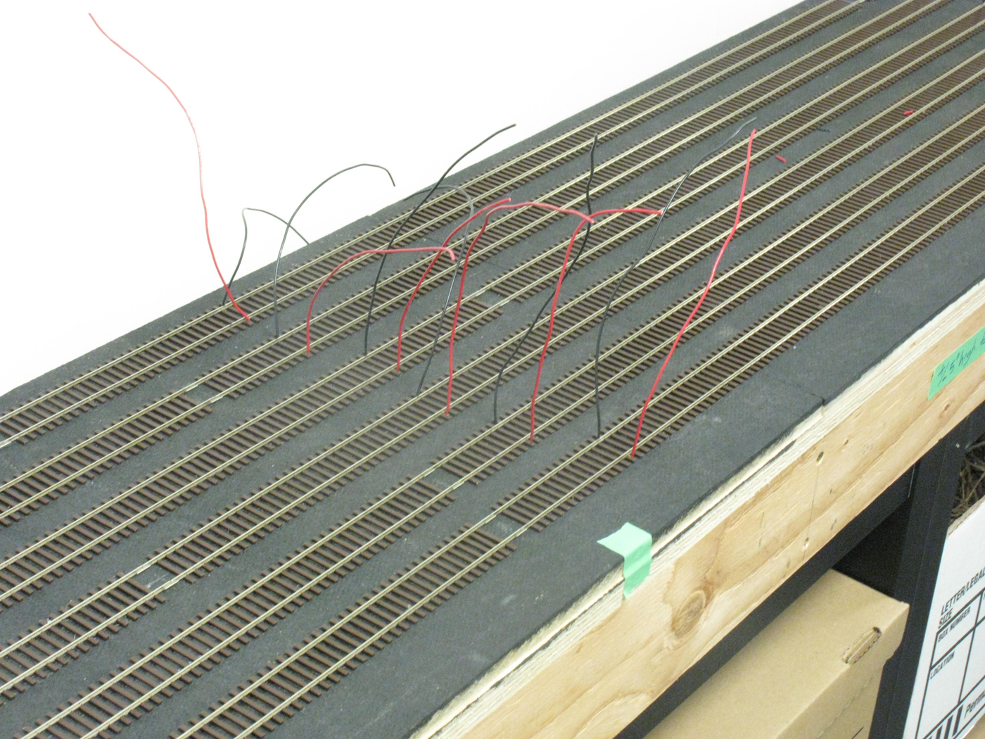
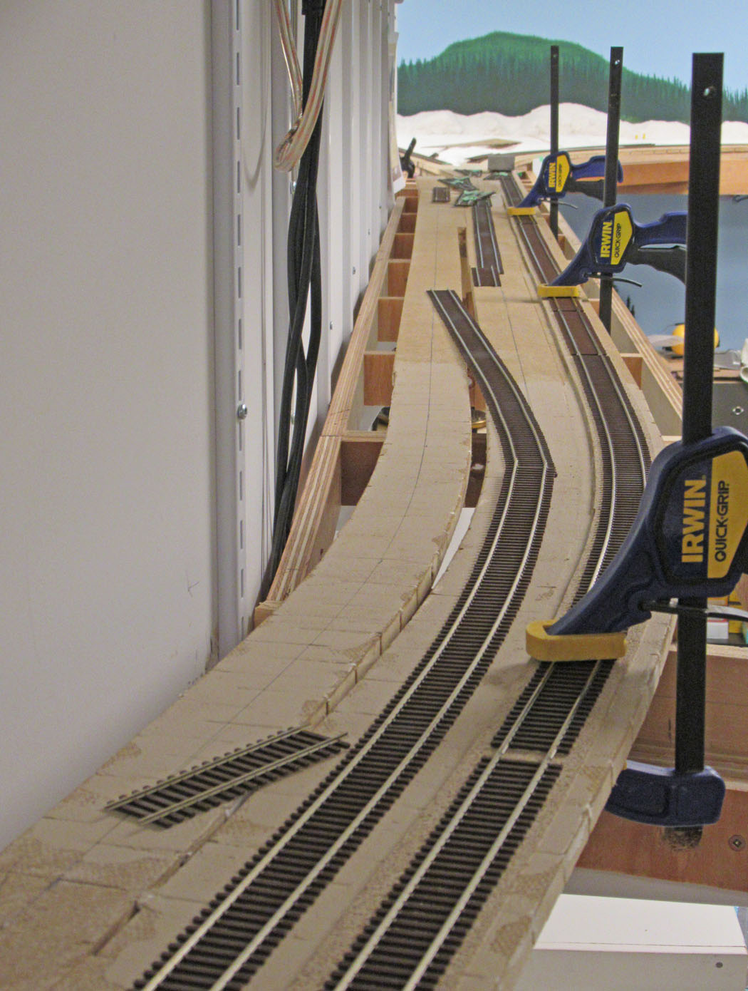
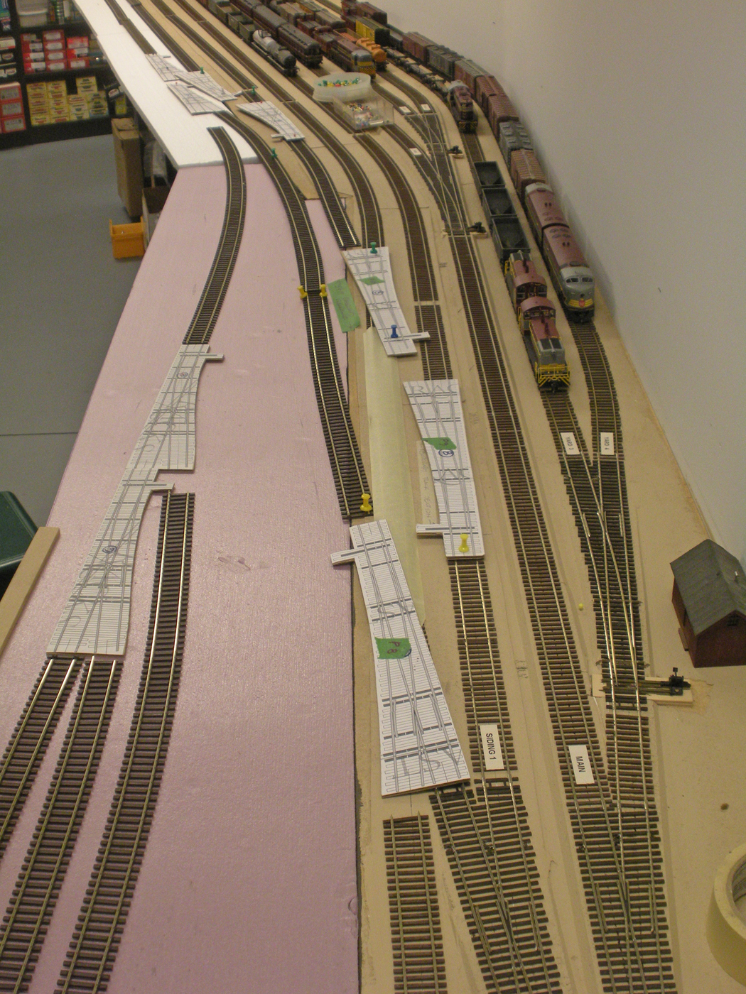
All the turnouts are Shinohara code 70 that were modified to be more DCC friendly, and all the flextrack is Micro Engineering code 70. All the flextrack was laid out and shaped very carefully so I would not need to manipulate it much when it came to installing it. Each piece of track was labelled with corresponding labels placed on the roadbed so we could keep track of which pieces went where. The track was prepared for painting and then airbrushed and weathered using a combination of Floquil and acrylic paints. This is the first section of track on the layout to be painted and weathered, so this was another learning curve process for me. Once the track paint had dried, it was installed in the same fashion as the previous trackwork on the layout.
The final steps required to complete this phase were to design and construct the vertical lift bridge that spans across the room entry door, connect the track to the relocated staging yard, and test it all. The lift bridge was engineered by Ken Catlin (who did the swing gate on the lower level) using heavy duty 20” travel drawer glides and a piece of aluminum T shaped extrusion I scavenged many years ago. A temporary piece of 2x3 with hardboard gussets was used for the bridge part to test the alignment and ease of the vertical travel. Once satisfied, the permanent bridge was constructed using plywood gussets between the drawer glides and the aluminum extrusion. After some tweaking, the track was then installed over the bridge and into the staging yard. The final step was to actually run a train over it!

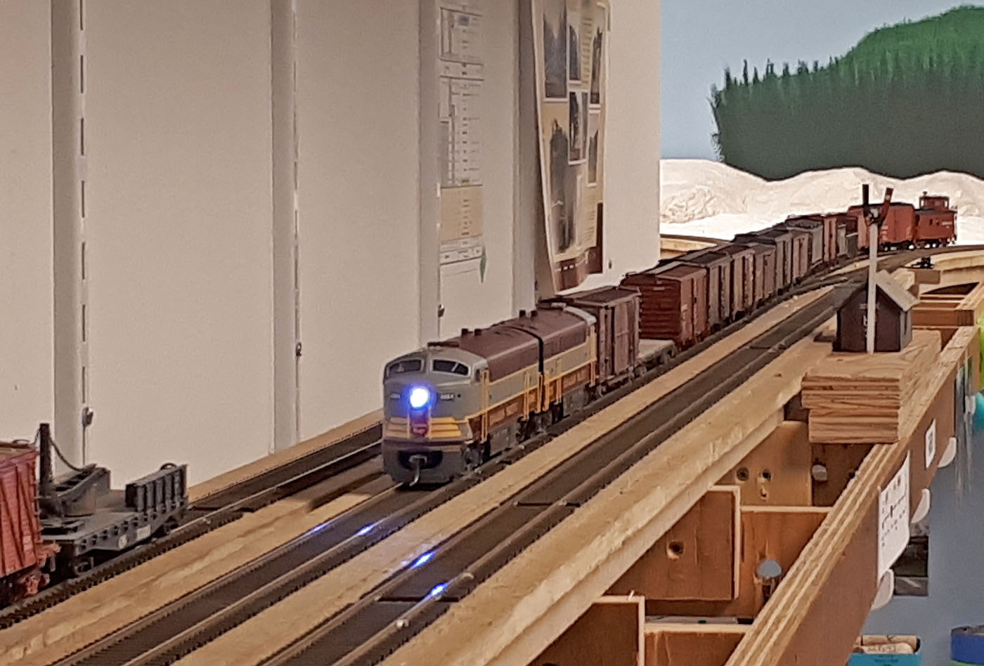
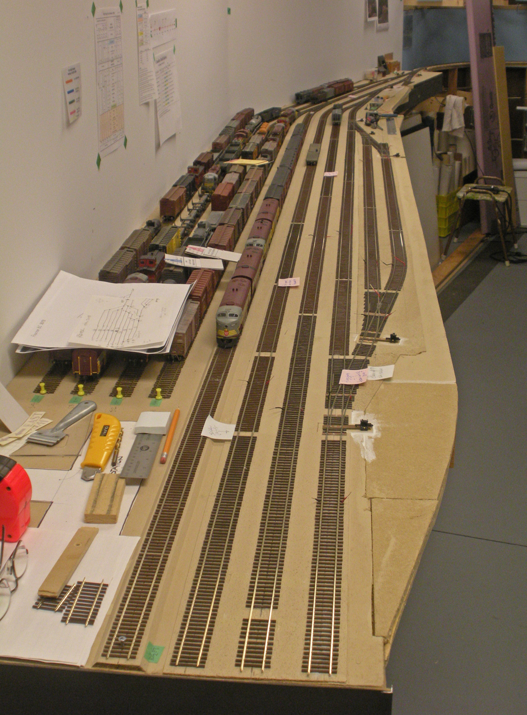
This is an eastward view of the temporary west staging yard modules with all the trains removed.
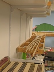
This is a westward view looking over the end of the west staging yard showing the new module framing and spline roadbed construction at Farron in the distance.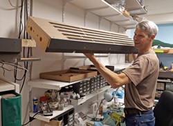
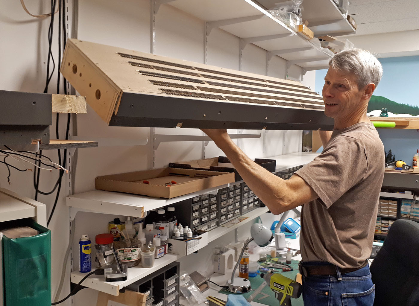
Once the track and wiring connectors were removed, the westerly 4 ft section of the temporary west staging yard was disconnected and simply lifted out by the author. All the bus & feeder wiring remained under the modules so it could simply be reconnected once the yard was reinstalled.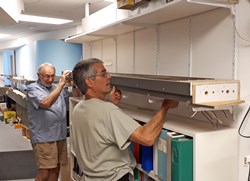
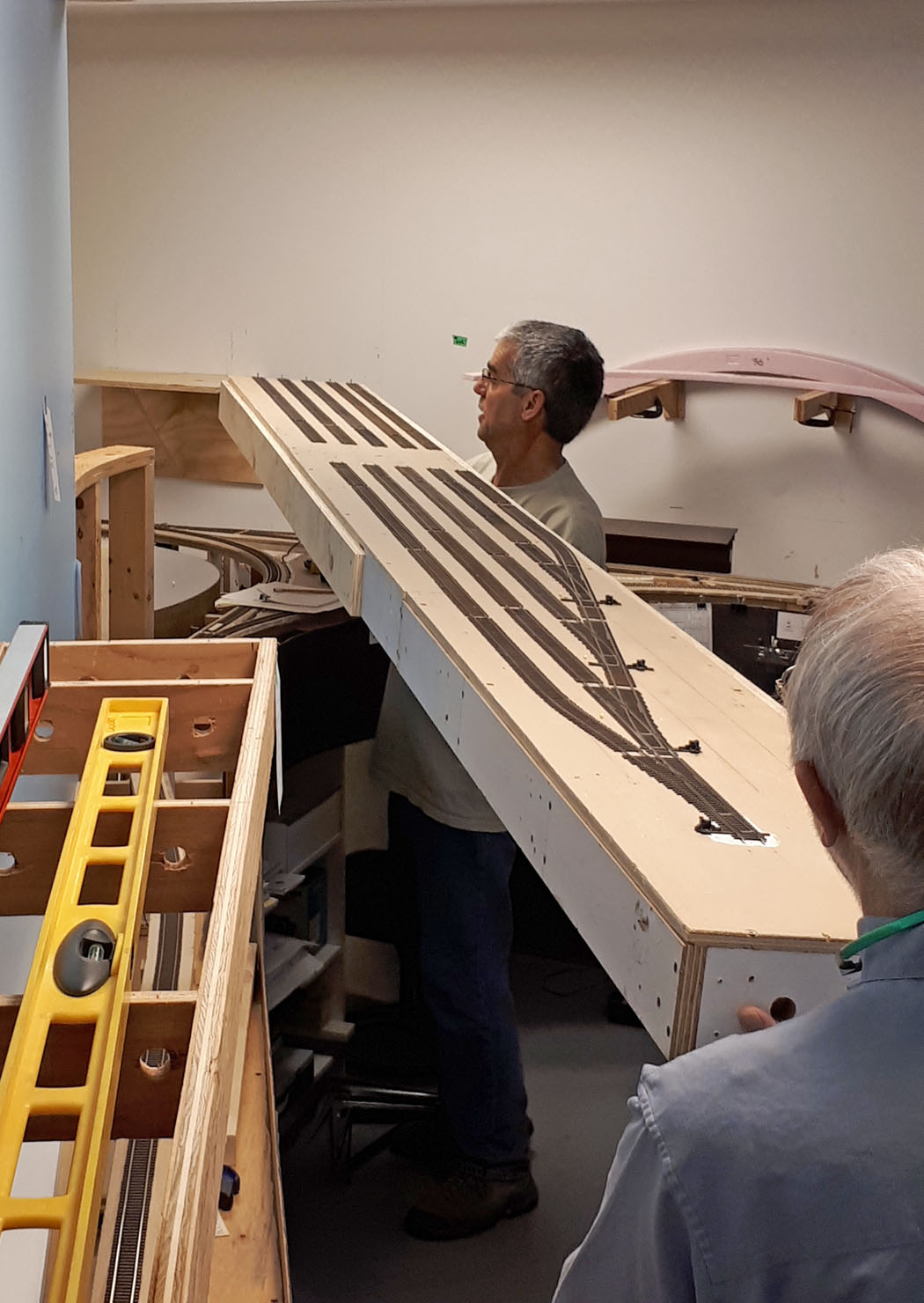
Ken C and John M lifting are lifting out the longer 8 ft section of the staging yard. The holes in the end are for the wiring harnesses to pass through to reconnect to the other yard module.
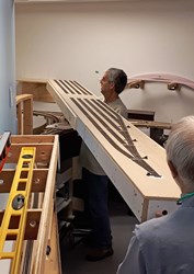
The 2 yard modules were reconnected with plywood strong-backs at the joints to form the complete 12 ft long west staging yard which was then lifted up onto prepared brackets and other supports. The gaps in the tracks which can be clearly seen are where the module joint occurs.
Here we see the west staging module in place and connected to the permanent module on the left side of the photo.

Meanwhile, the gap left by the removal of the staging yard was filled in with a series of 2” high prebuilt plywood framed modules supported on the wall shelving brackets.
These modules took a fair bit of effort to align and level out. Here we see 4 standard 48” modules with a custom angled module all in place and connected – ready for the spline roadbed system to commence.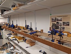
This is the same set of modules with the construction of the spline and roadbed well underway. This view is eastward looking towards the end of the previous mainline.

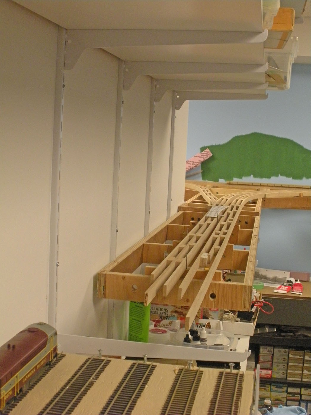
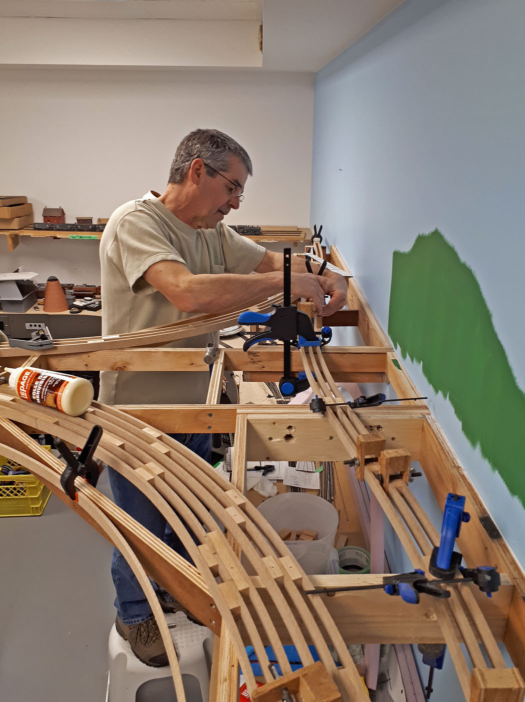
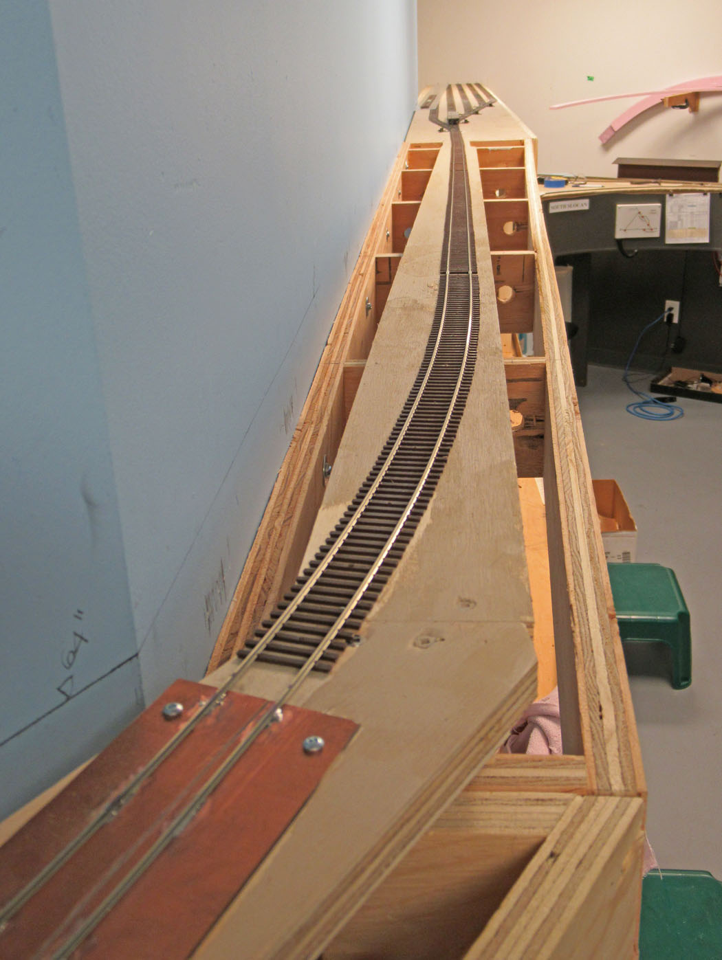
Back in the Farron area, Ken C is working on the spline for the wye track where the pushers and other equipment will be reversed. Farron is the summit of the line and the highest point on the layout at 67” above the floor.
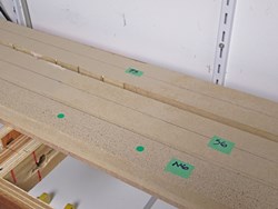
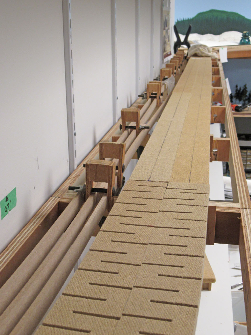
The Farron roadbed installation followed the same methodology as has successfully been used throughout the layout. The notches in the foreground roadbed are to facilitate curving it.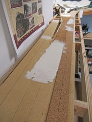
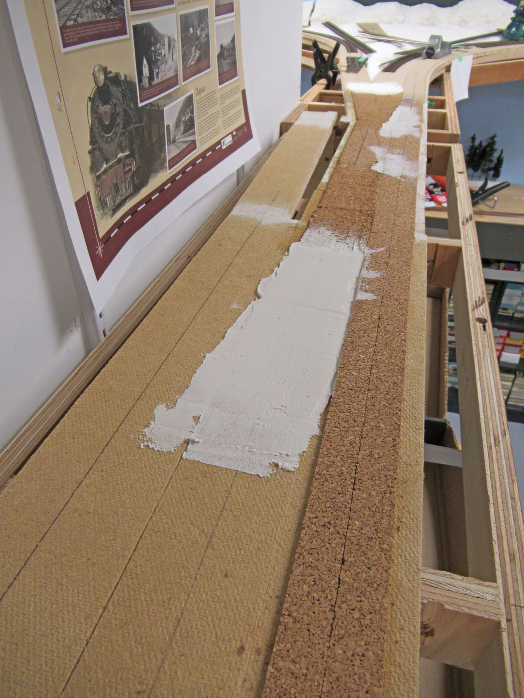
This view is in the same general area as the preceding photo and show how we use 1/8” cork to elevate the mainline from the siding. And use drywall mud to taper the transition between them.
This photo shows the tricky connection between the original mainline spline system and the newly constructed spline extension.
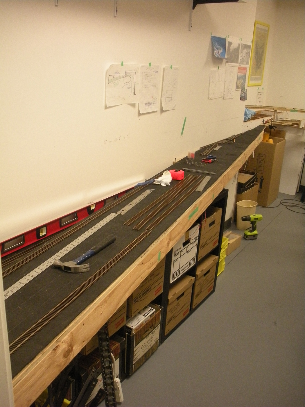
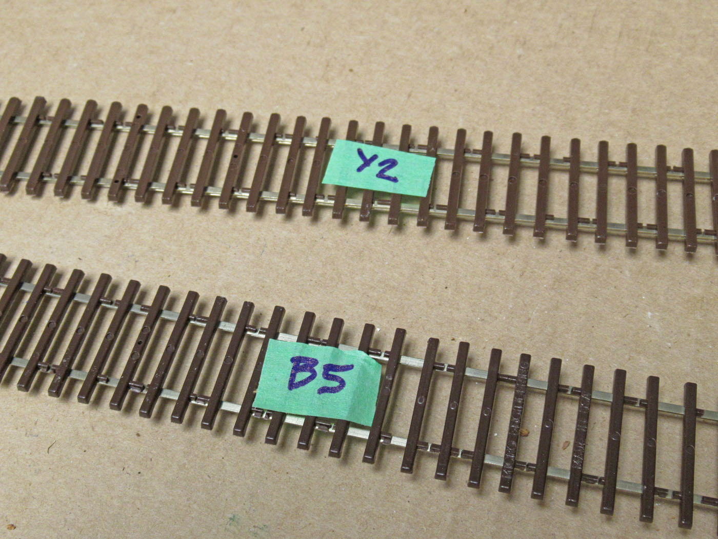
All the flextrack was pre-shaped since it would be pre-painted before final installation.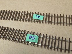
All track pieces were labeled with an alpha numeric code.
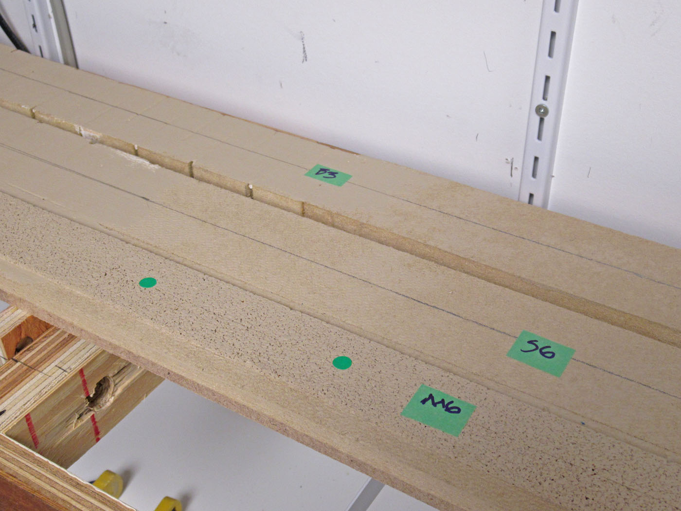
The corresponding locations for each piece of track and turnout was labeled with a corresponding label so we would know where everything went once the track was brought back from the “paint shop”.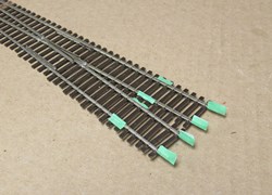
We installed pieces of tape at the rail ends and also where the feeders were to be located to minimize the effort required to connect everything back together. All feeders were located ahead of time and soldered on to the bus wires at the correct locations, and one end of all sections of flextrack received soldered rail joiners.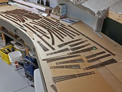
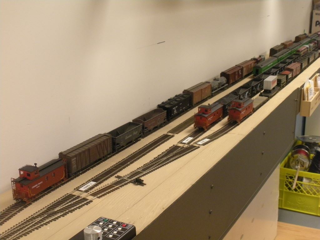
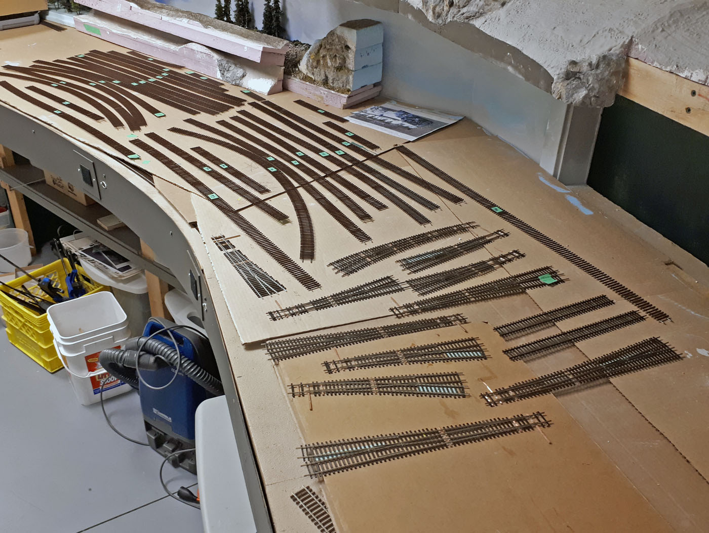
All the flextrack and modified Shinohara turnouts were all inventoried before taking them out of the train room to be painted and weathered.
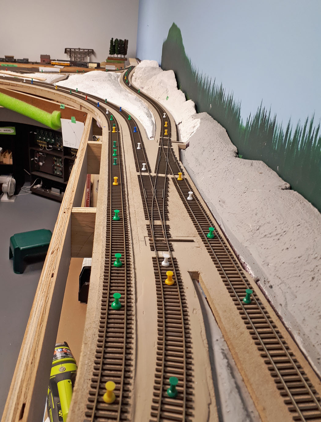
This is a view of the Farron siding area trackwork being installed

Another view of the Farron trackwork as it is progressing. The wye tracks can be seen in the upper part of the photo.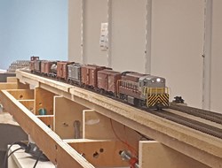
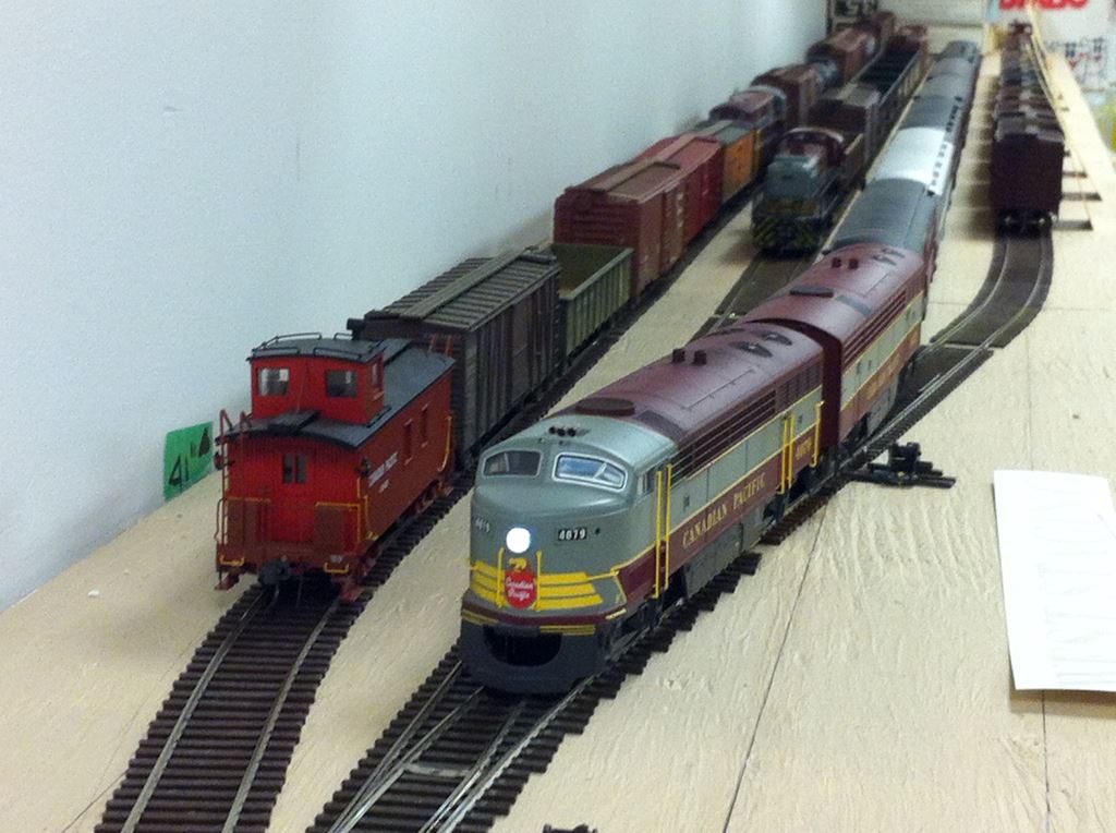
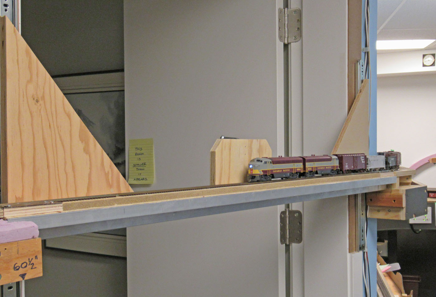
Once the trackwork was completed through Farron and up to the room entry door, we tested it with a couple of trains.
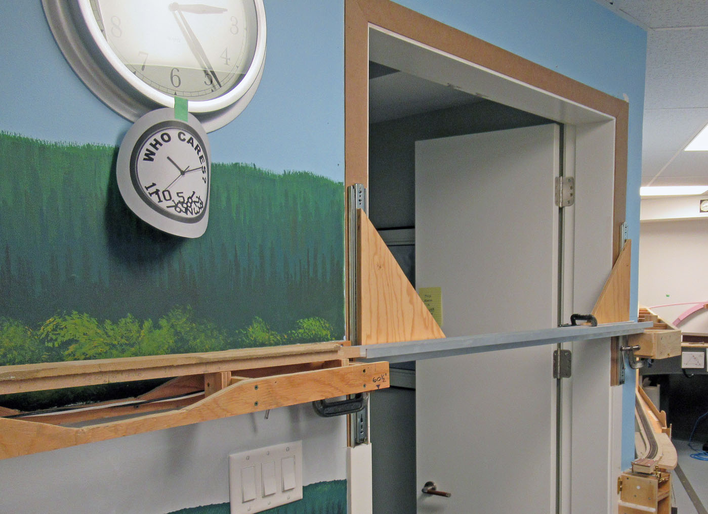
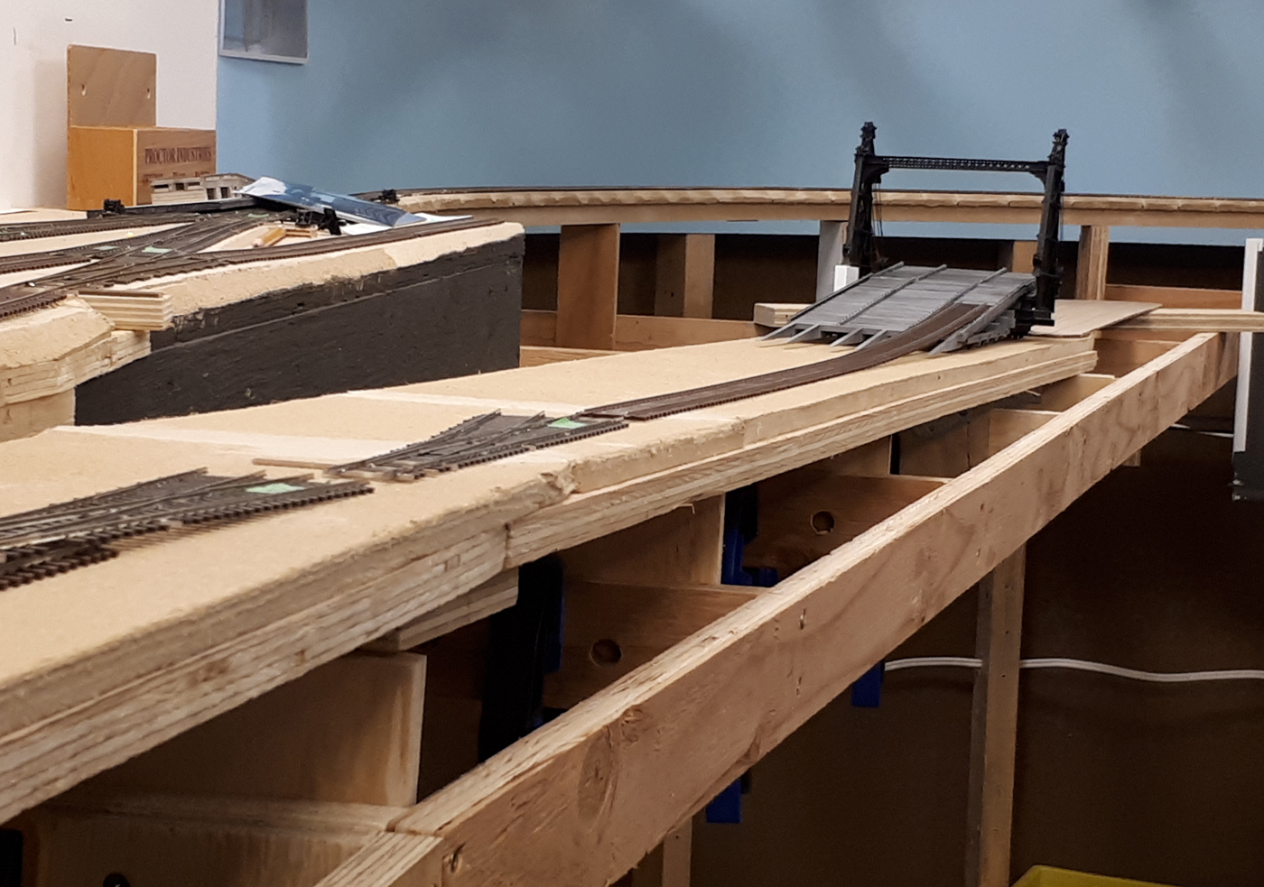
It was now time to turn our attention to the lift up bridge that would span the room entry door. Here is pre-construction view of the 54 inch span looking out of the train room.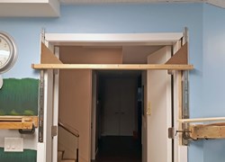
A similar view with the vertical heavy duty drawer glides and a temporary 2x3 “bridge” in place to test alignment and movement.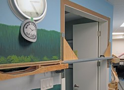
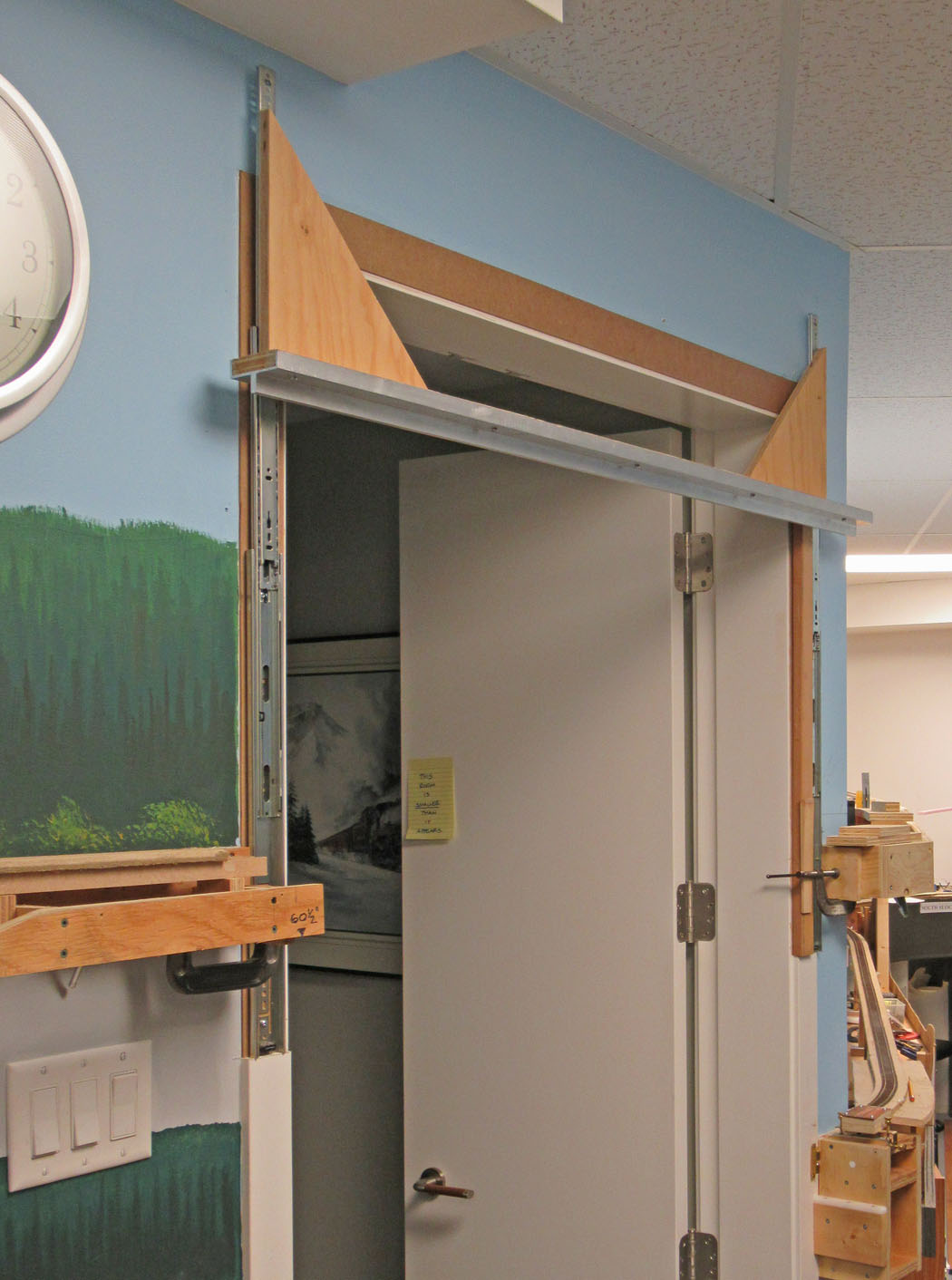
This view looks westward with the permanent aluminum bridge in place for test fitting.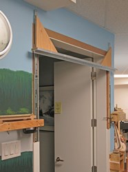
A similar view with the bridge in the raised position. The travel of the drawer glides prohibited the bridge from rising to be completely clear of the door opening, however, it is about 7 ft clear beneath it.
Then we needed to complete the trackwork from the west end of the bridge into the staging yard – which is in the distance.
And finally, trains had to be run across everything to test it all.


-
-
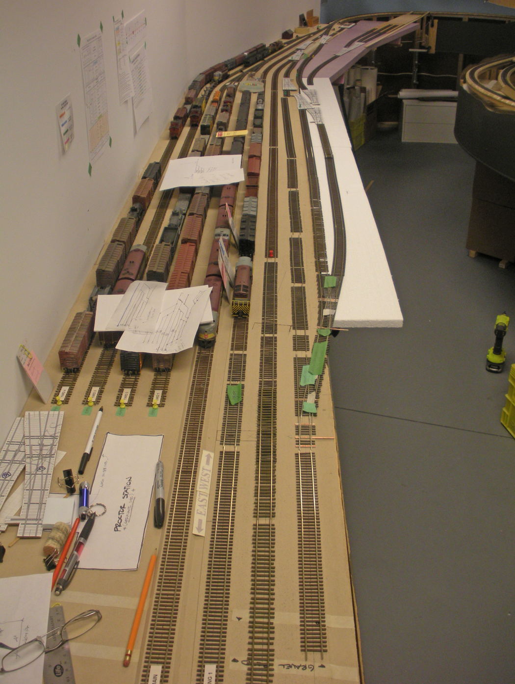
Spring 2018 East Staging Yard Expansion
-
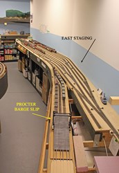
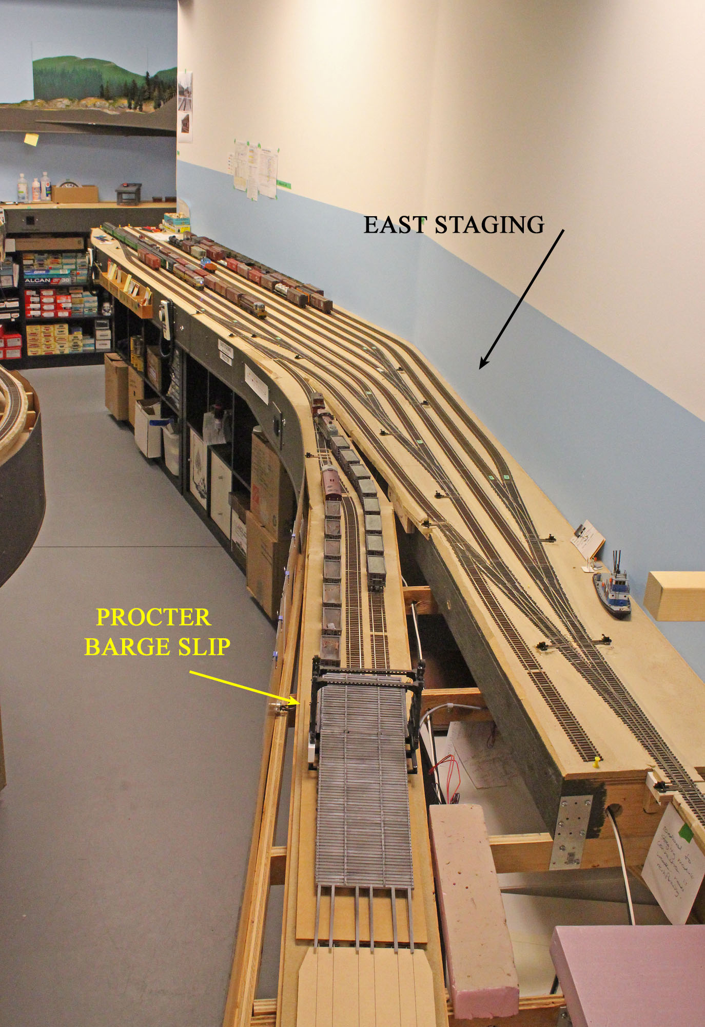
The receipt of the wonderful model of the Procter transfer slip structure from Patrick Lawson prompted us to complete the trackwork for the east staging yard – which includes the Procter BC transfer slip location. Having he actual model greatly assisted in working out the geometry of the new tracks.
-
This staging yard is actually a combination of a staging yard representing eastern destinations, and the actual location of Procter, BC located on the CPR mainline east of Nelson.
-
A partial yard has been in operation since we commenced operations on the layout many years ago. It was now an opportune time to finish it off from a track perspective. Plus, having the transfer slip allowed the inclusion of some interesting prototypical operations.
-
As is typical, we did various mock-ups of the track and possible framing additions, playing with the desired objectives against the available space. Even though this is less “busy” area of the layout, we wanted to minimize the reduction of the aisle width.
-
The completed yard was put into service during the 2018 Railway Modellers Meet – you can see photos of it in the Operations Photos section of the web site.
Here are a series of photos showing the progression of the work;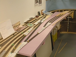
Because the transfer slip configuration was a space planning driver, we mocked up a rough configuration for it using cardboard templates for the transfer slip and barge and associated tracks on a piece of Styrofoam supported by some temporary framing joists.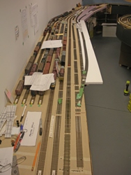
We roughed out the additional yard tracks on the existing benchwork and a temporary piece of Styrofoam cantilevered off the edge.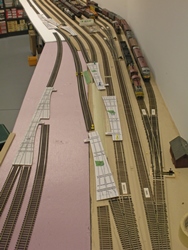
Here we see the rough configuration for the added yard ladder turnouts and transfer slip tracks. We use cardboard turnout templates based on Fast Tracks samples.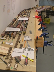
Satisfied with the additional yard track layout, we added on the necessary cantilevered section of benchwork.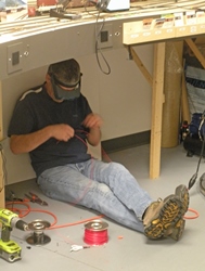
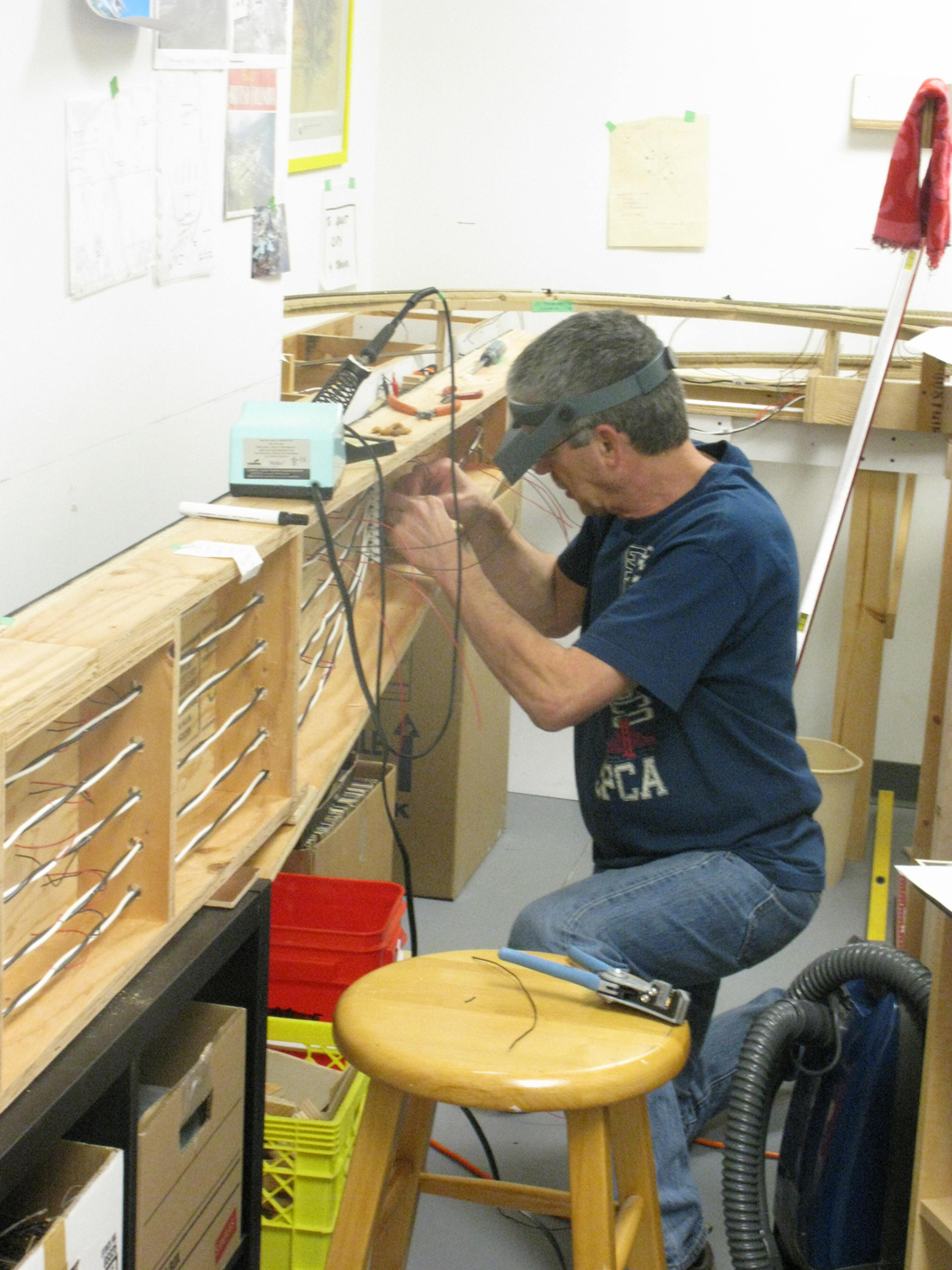
During the original construction of this yard, we rouged in numerous track feeders under the layout in anticipation of the future, however, all this added track and turnouts required even more feeders. Here we see Ken C working on them.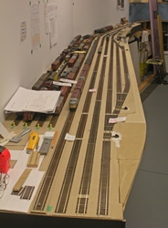
Here is a view looking down the yard with all the new tracks completed. The transfer slip area in the upper right corner has not been done yet.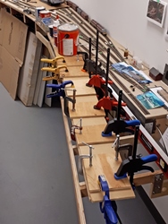
We now move to the transfer slip area and installed the cantilevered joist framing and plywood subbase.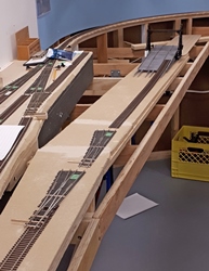
The roadbed is installed for the transfer slip and the tracks are being laid out for the final locations.
This photo gives a good perspective on the grade changes between the yard, slip approach tracks and the physical transfer slip structure.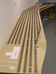
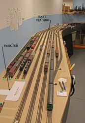
An overall view of the almost completed yard area looking west.
An overall view of the almost completed yard area looking east.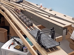
A view of the transfer slip area with the structure just loosely in pace for now. There is a lot of collateral work to do before the structure can be permanently installed. For operations purposes, we use the approach tracks as a staging area for cars that will eventually actually be loaded onto the barge.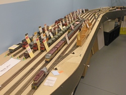
To prepare for the upcoming operating sessions, it was necessary to restage all the equipment in the expanded yard and sort out all the paperwork!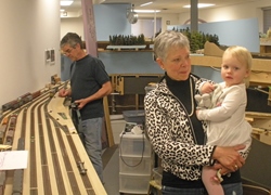
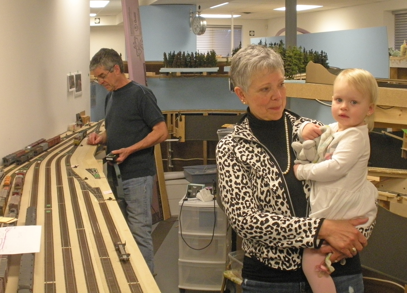
And, of course “Management” (Margot and granddaughter; Wren) was called to approve the work as it progressed! We see Ken C in the background trying to avoid their scrutiny!


-
-
Fall 2017 Nelson Diesel Shop Base Installation
-
This structure was constructed in 1955 to accommodate the necessary servicing for the diesel locomotives that were being introduced into the Kootenay area. Our model required the layout top to be lowered 1.25” to accommodate the depressed pits.
After finalizing the track configuration on both sides of the shop building as noted in the previous entry, we removed and lowered the necessary section of framing and employed multiple screws to hold the base down, and most importantly, allow us to remove it to complete surrounding work, and for future work.
The following photos show some of the effort required to complete this work. -
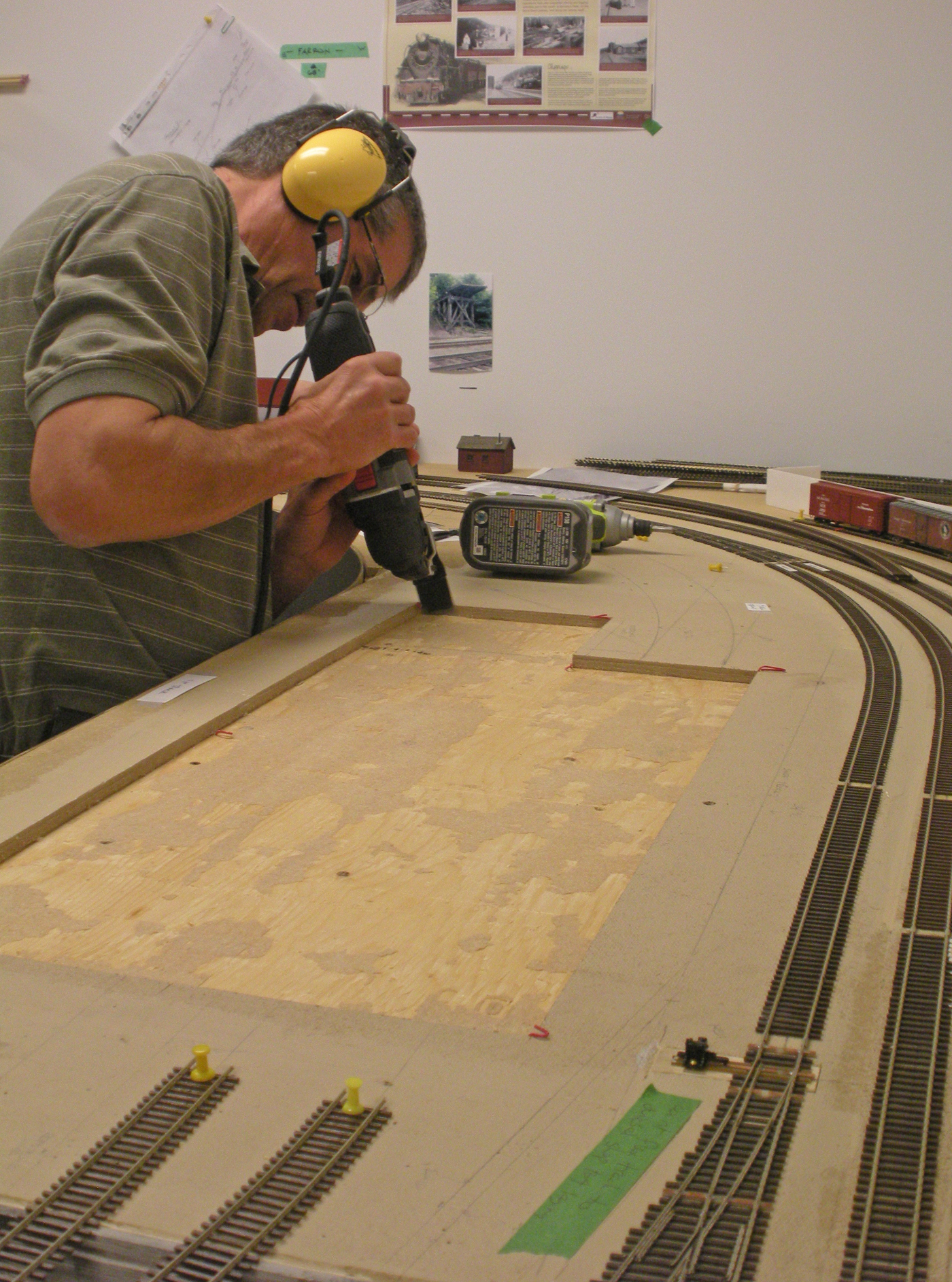
Here we are removing the fibre board base material from off the plywood subbase where the diesel shop is located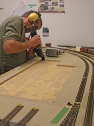
Ken C is using a cutting tool to cut through the plywood without damaging the underlying support joists.
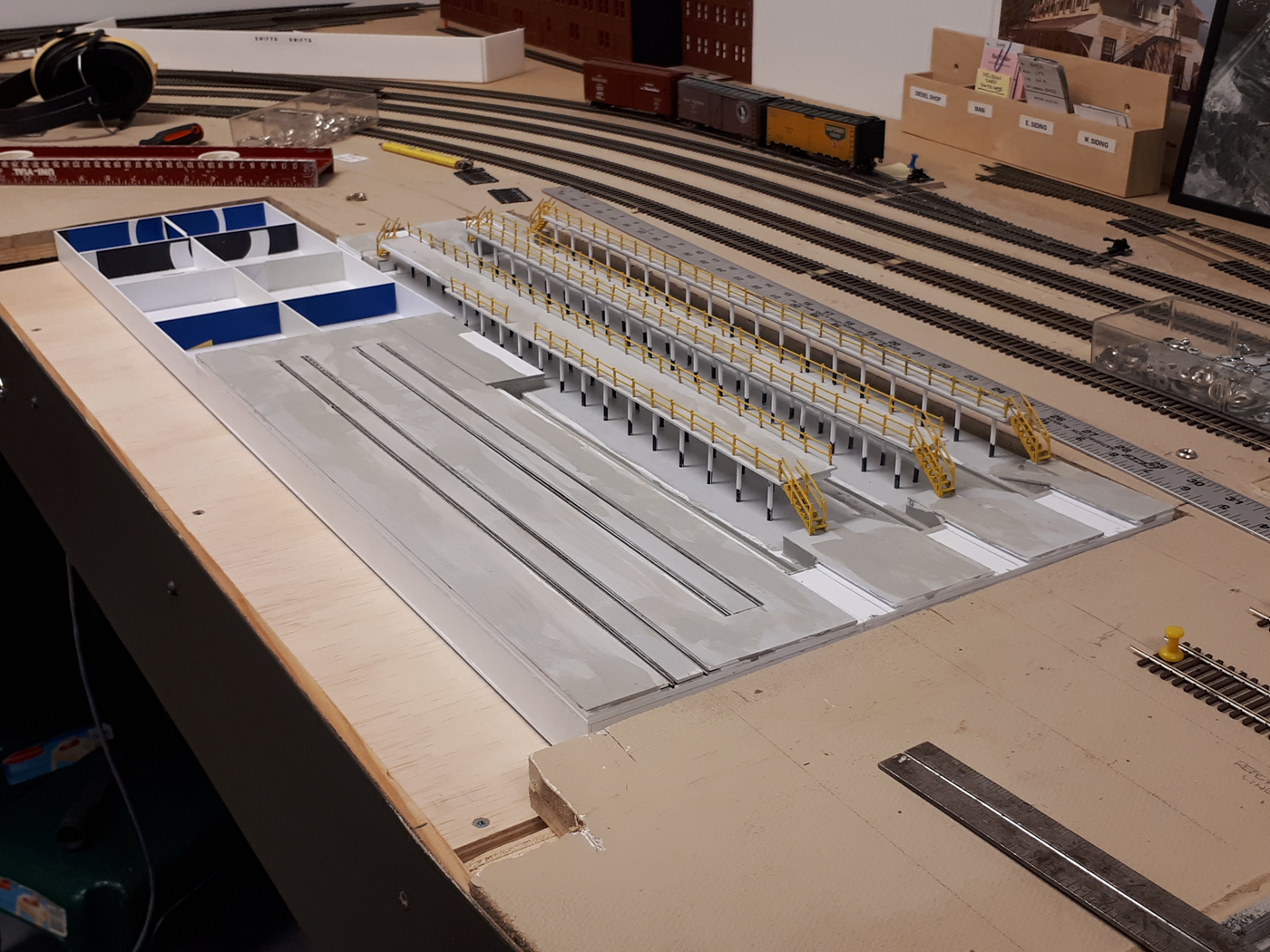
The base is being test fit prior to securing the framing cleats below the layout that support it.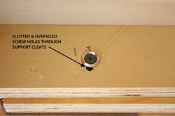
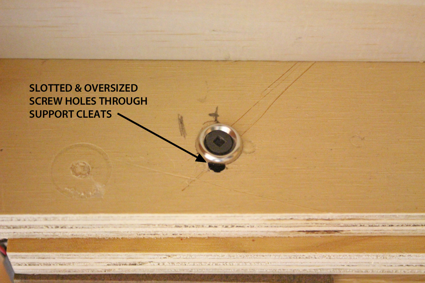
The cleats have slotted & oversized screw holes in them to provide some fine tuning adjustment of the base once the track installation commences. Pan washers were used to “bite” into the framing when tightened to avoid future movements.
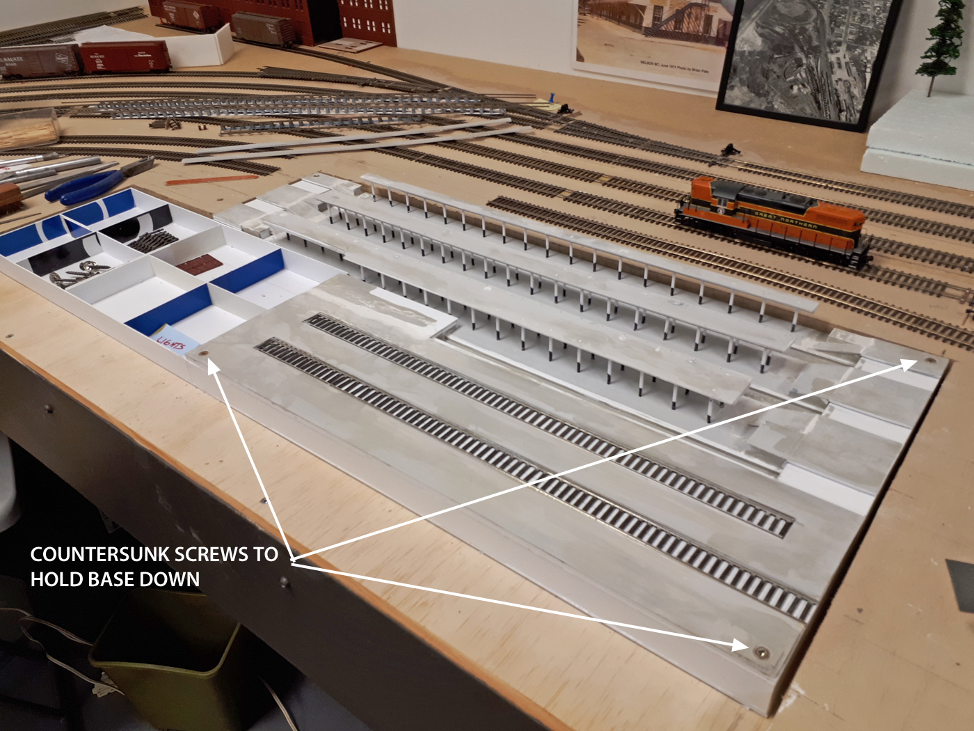
The styrene base is very rigidly constructed, so we opted to screw it down in several locations with wood screws that were countersunk into the thick floor. These screws will ultimately be covered with “stuff” like pallets or misc equipment. -
-
August 2017 Nelson Diesel Shop Track Configuration
-
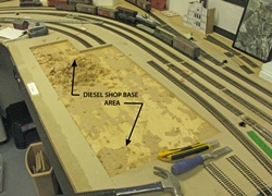
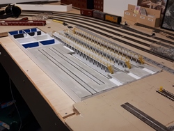
To allow finalizing the exact location of the diesel shop, the configuration of the tracks on both sides of the building needed to be determined.
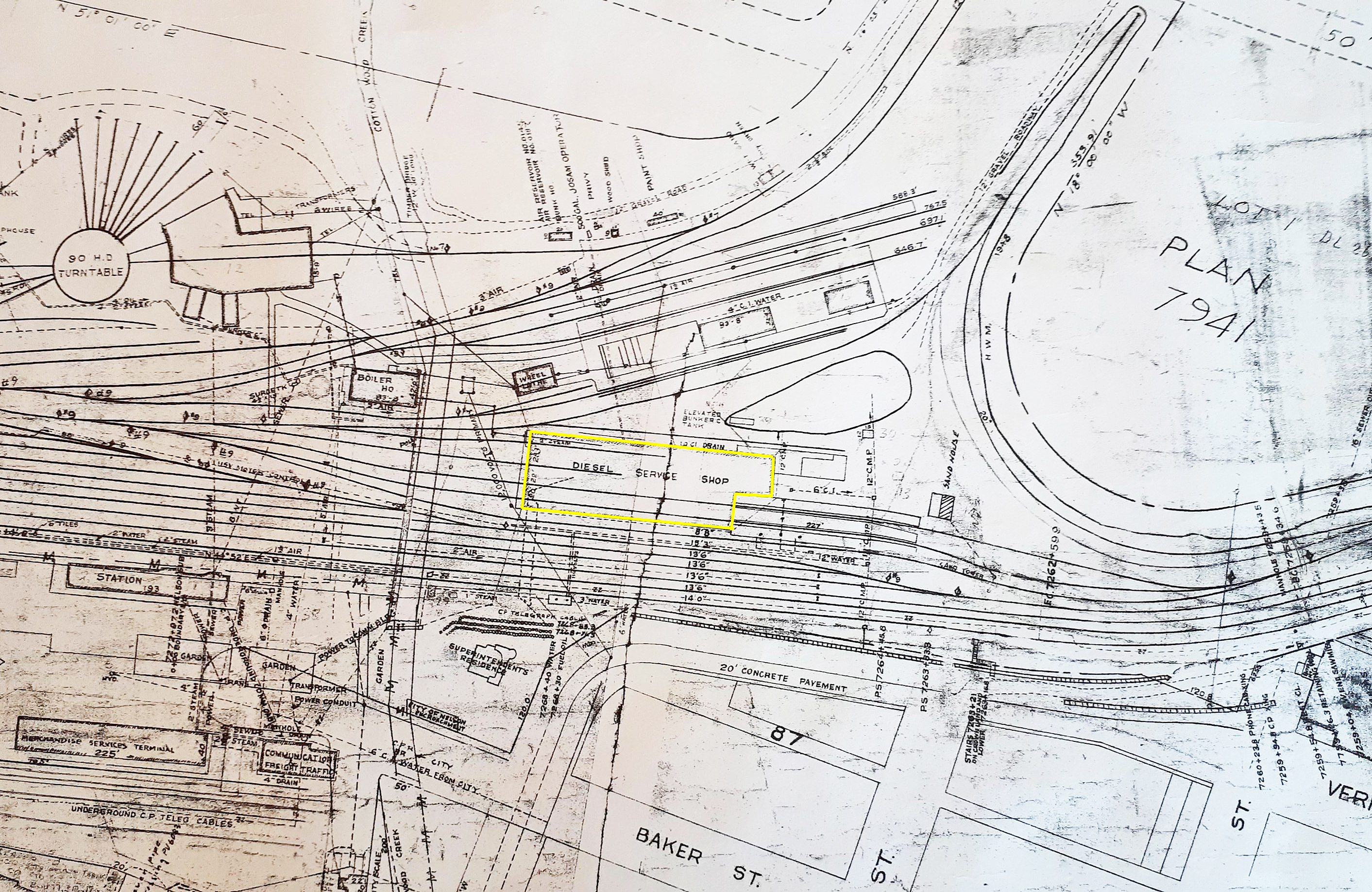
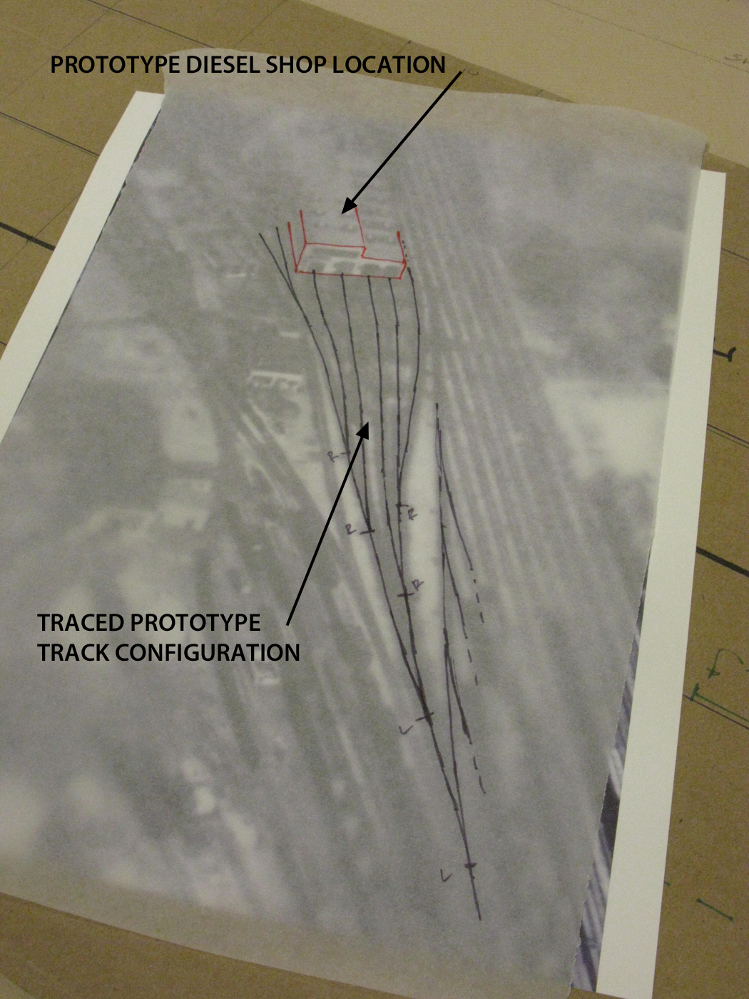
Using an enlargement of an aerial photo of the yard, I sketched the prototype tracks on a trace paper. This was compared with the actual track configuration shown on a yard plan that I have, and armed with this, I proceeded to try various track and turnout configurations to see how close we could get. Once satisfied with a layout as close as possible, the tracks and turnout locations were marked on the roadbed and the position of the diesel shop was confirmed.
The following photos show some of the steps for this process;
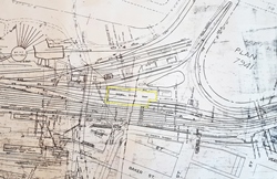
This plan is taken off the Nelson yard plan print and is dated in about the late 1950’s. It shows the actual track configuration on both sides of the diesel shop.
Here I have traced out the track configuration on the west side of the diesel shop by overlaying trace paper on a c/a 1960 ish aerial photograph.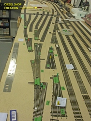
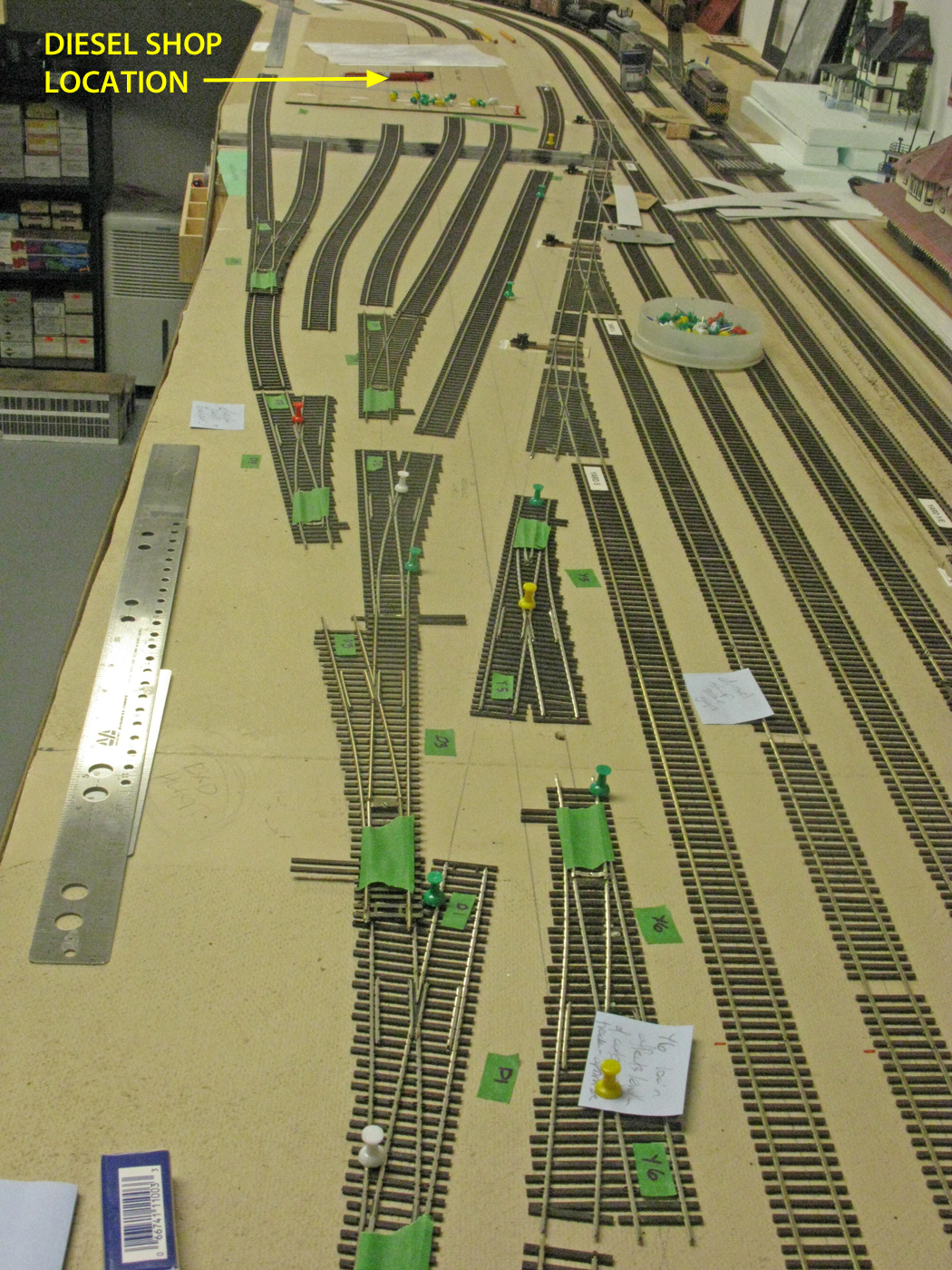
In this photo, we are trying out different track and turnout configurations in an attempt to replicate the prototype as closely as possible.

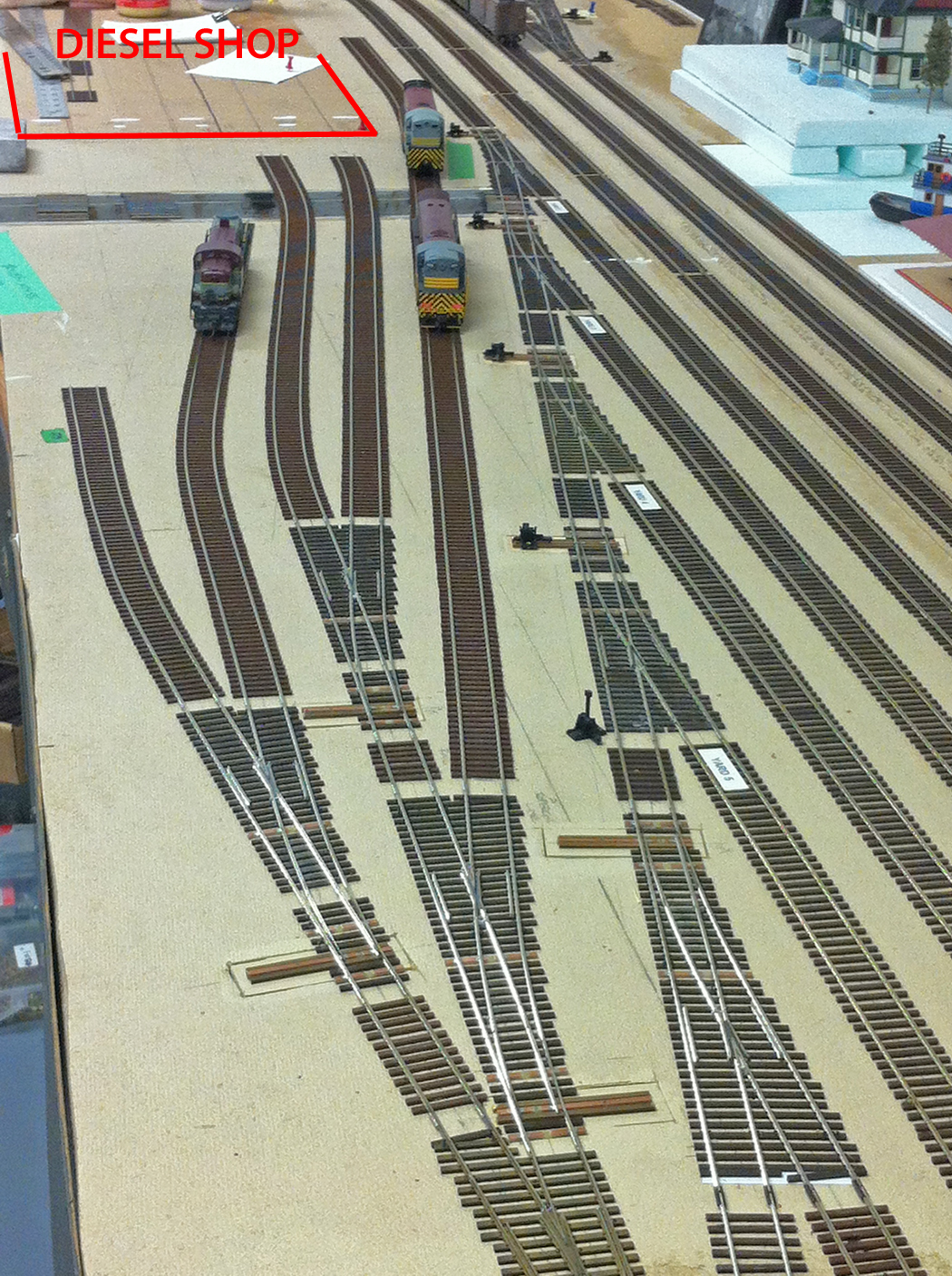
This photo shows the final model track configuration. While not exactly correct, it is quite close given the constraints of the available area. The track on the far left side of the photo still requires one more turnout for track #4 in to the shop building. -
-
April 2017 cpr rossland subdivision staging yard construction
-
This prototype subdivision was very busy and generated a lot of traffic for the CPR, particularly in the early years. CPR timetables in the late 50’s and early 60’s showed several trains going in and out of this subdivision daily! It was determined during the earliest planning stages for the layout that this would be modelled as a staging yard, although the exact location and design was not established at that time.
The following series of photos provides a progressive overview of the construction and implementation of the 12 foot long, 6 track Rossland Subdivision staging yard. The turnouts will have switch machines installed and we intend to use a power routing strategy to align them and also provide power to the tracks. This work will be completed this summer.
Here we see Ken C assembling the various plywood framing components that were pre-cut in the garage/shop.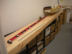
This shows the completed framing with the plywood top installed.

The roadbed material has been glued down with white glue and has been clamped firmly in place until the glue sets.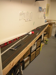
The roadbed is done and has now been painted flat black so it is not too obvious when the Slocan City upper deck is installed above it.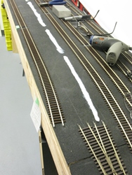
Track installation is proceeding using Micro Engineering code 70 flex track and #6 turnouts. The track is glued down and the turnouts are spiked down – in case we need to pull them up in the future!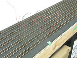
Here we see the track feeders protruding above the layout.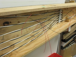
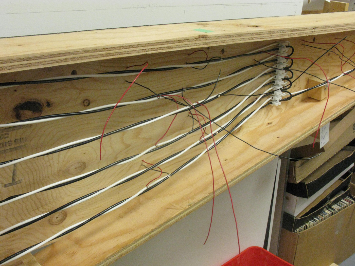
This is a view of the underside of the module while it is actually on its side. Each staging track has its own bus wire.
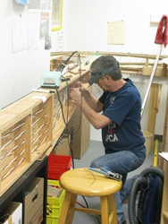
It is our practice wherever possible to complete as much under layout wiring while we have modules upside down or at least on their sides. It certainly saes us from the need to crawl under the layout to do this – at least most of the time! Here we see Ken C completing the termination of the bus wires into the terminal block.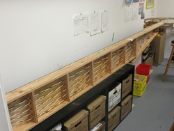
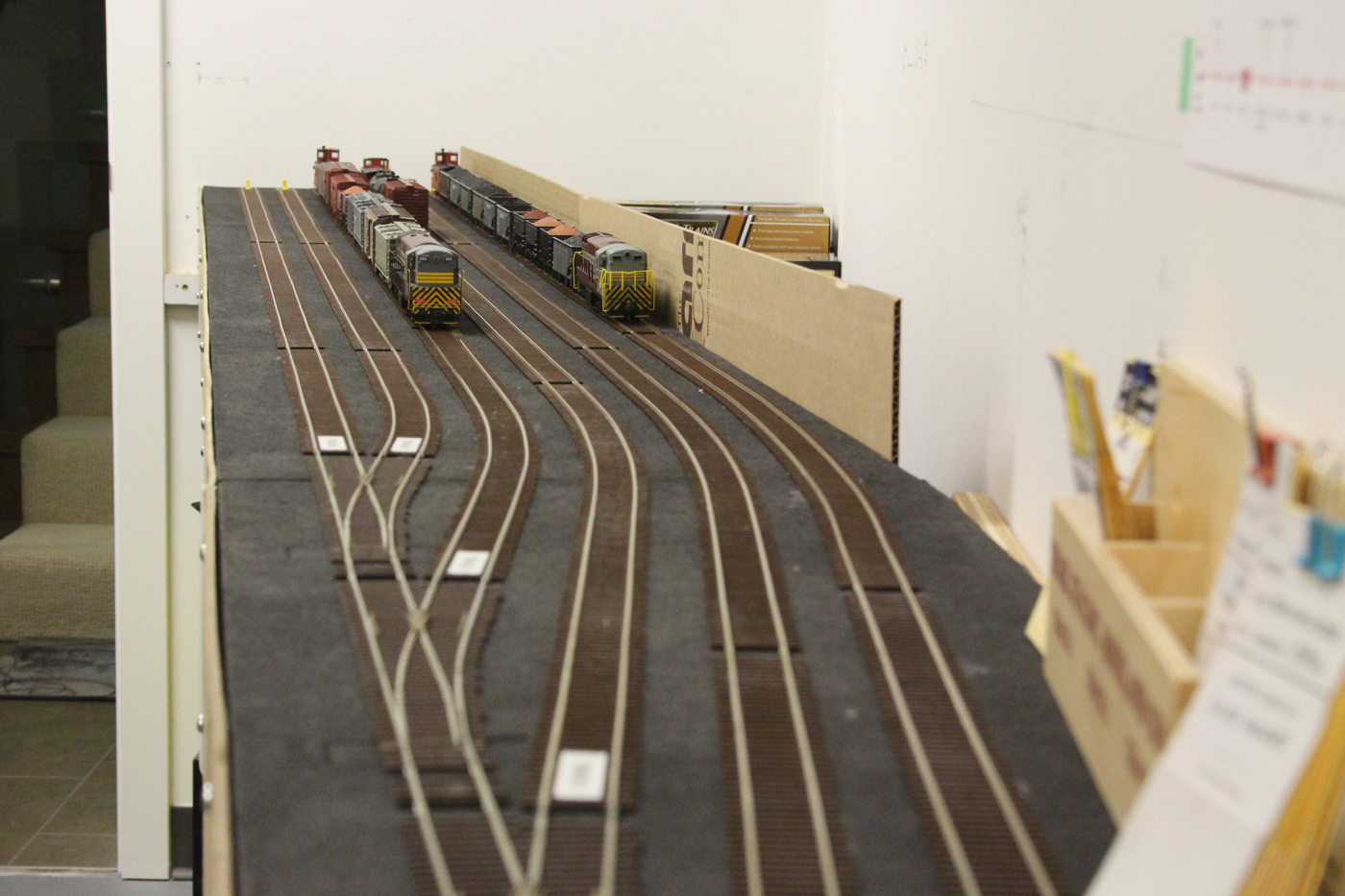
This photo shows the overall length of the entire staging yard with all the bus wring and track feeders installed. It is now ready to flip upright and be secured in place.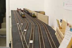
This is the completed yard now in service with a few trains staged in it. It is still pretty thin on freight cars, however that will change as we add more to the layout. -
-
Dec 2016 to Mar 2017 - Nelson west modification
-
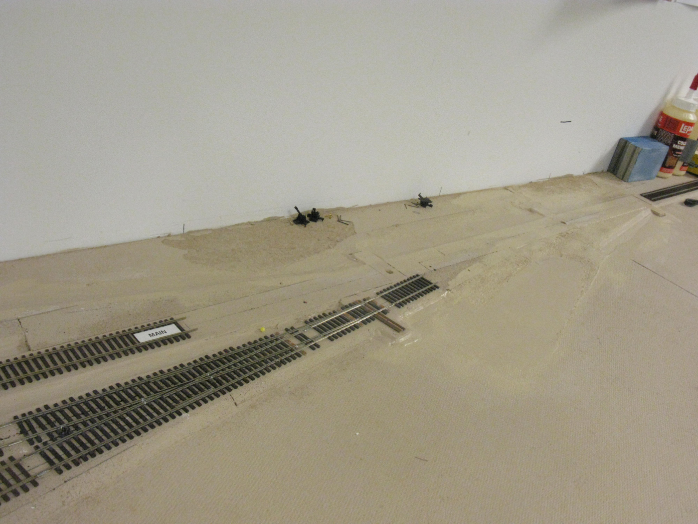
One of the unique elements at the west end of the Nelson yard is the two curved tracks that the railroad used for cleaning out various freight cars. These tracks were typically quite full and usually had a debris field around them – particularly in the earlier years.
After mocking up numerous configurations on how these could be incorporated into the available space on the layout, we compromised a bit to maximize the length of these tracks at the expense of the turnouts being in exactly the correct prototypical arrangement.
We then proceeded to remove several existing turnouts that needed to be modified to be DCC friendly and we also removed a spur that was installed during the original yard construction but was not really correct and would interfere with future scenery objectives in this area.
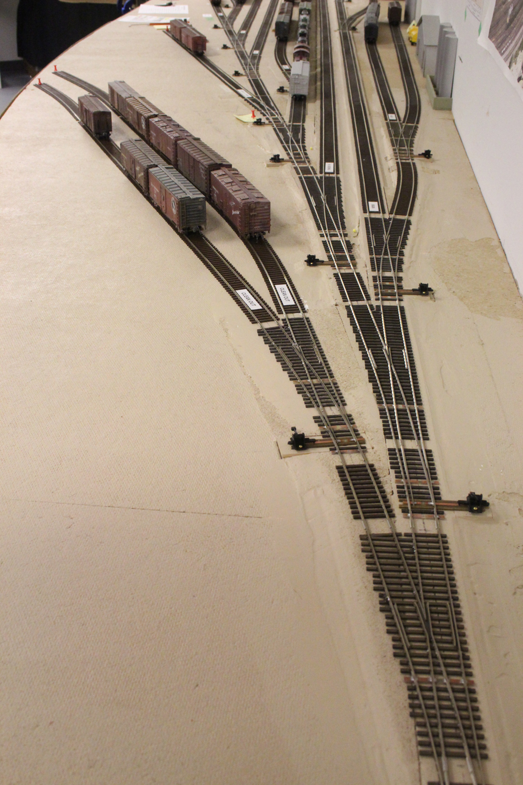
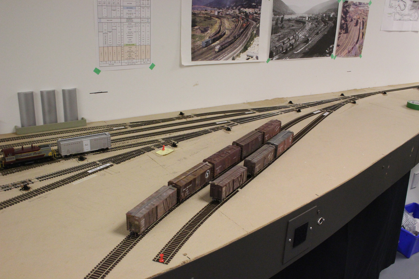
We are quite pleased on how this modification turned out, and it has certainly added to the Nelson yard work load.
Here are some photos of the work and completed configuration.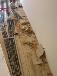
We have removed the Nelson brewery spur and associated roadbed and turnout.
The roadbed has been repaired and everything has been painted with the standard ground colour. Two mainline turnouts have also been removed to be modified to be DCC friendly.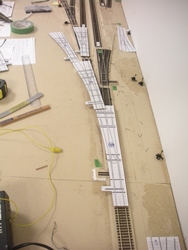
This is a photo of one of the many track configurations we experimented with.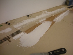
This shows the revised and added cork roadbed material installed for the new turnouts and track for the clean out tracks. To transition the levels, we taper the cork with a sure form tool and use standard drywall mud compound.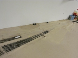
This is the same area as the previous shot with everything painted and now ready for eh track to be installed.
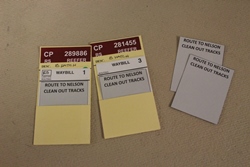
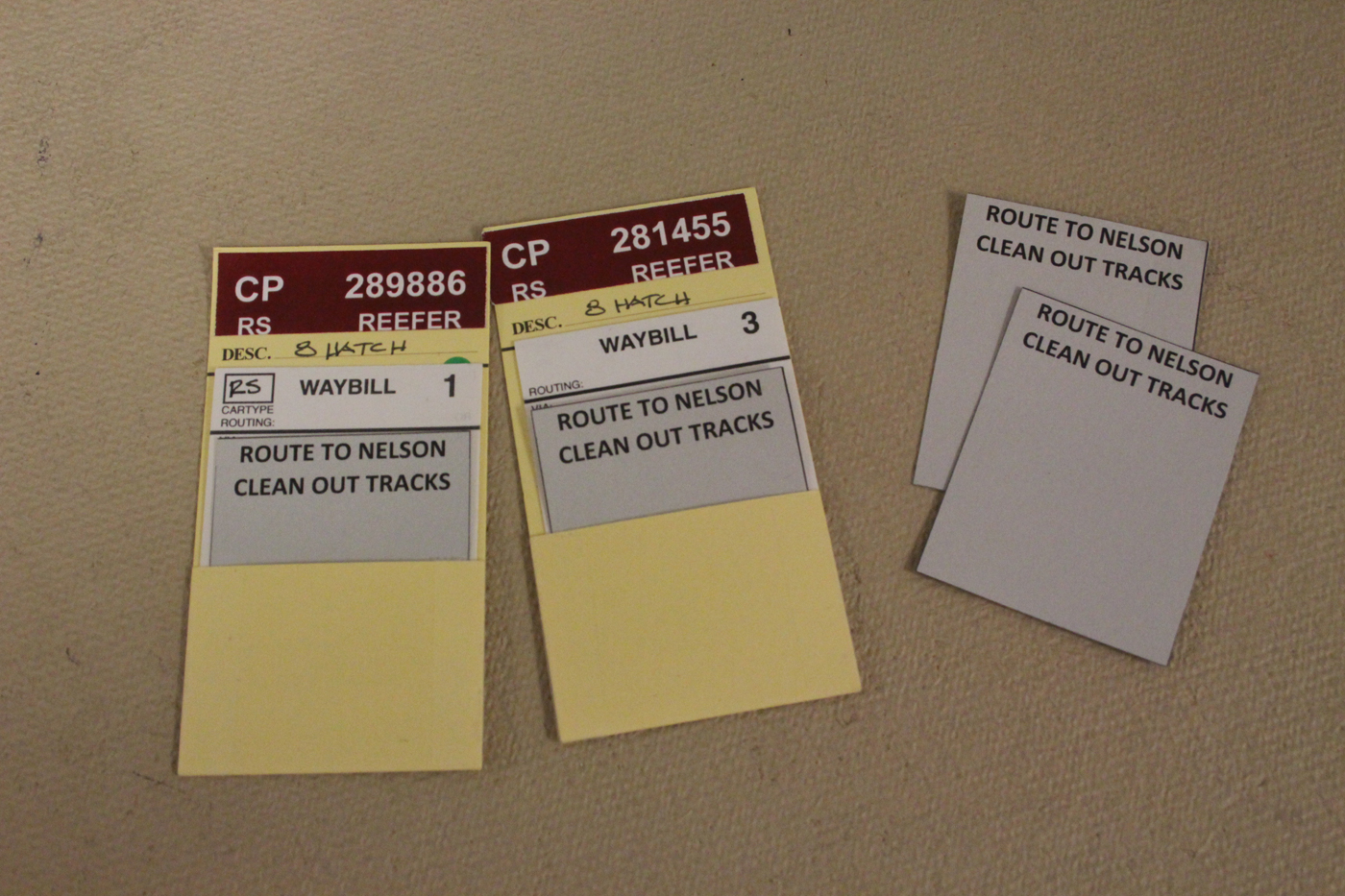
Here we see the Route to Nelson Clean Out Tracks cards that we insert into the car cards on top of the way bills. We add, or remove these between op sessions as part of the restaging process.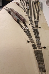
These shows the new clean out tracks from different vantage points. (Photo 1)
(Photo 2) -
-
august 2016 progress photos (Fascias)
-
Here we see John G fastening a section of facsia in place along the GN line.
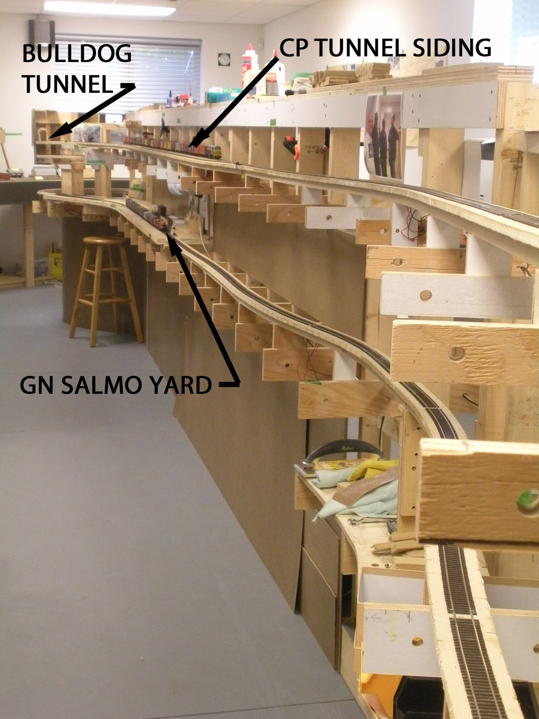
These 3 photos show the progression of the installation of the fascias, backdrops and skirting. The upper track Is Tunnel siding on the CP mainline, and the lower track is Salmo on the GN line. 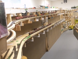
Photo 1.
Photo 2.
Photo 3.These 3 photos are the view as you enter the train room, again showing the progression of the installation of the fascias, backdrops and skirting.Photo 1. Photo 2.
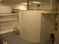 Photo 3.
 These 2 photos show the current state of the centre area of the layout.
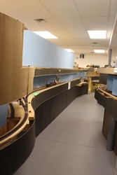 Photo 2.
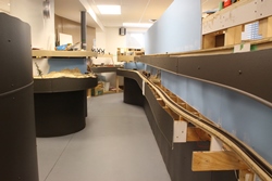
-
august/September 2016 progress photos (cOTTONWOOD CREek)
-
This shot shows the rough framing and basic construction of the Cottonwood Creek channel.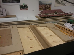 The roadbed is installed on either side, and the channel is being test fit into the framing.
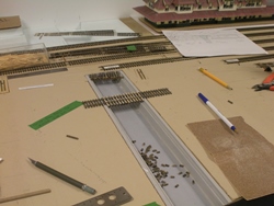 The channel has been painted and debris installed along the bottom of it.
 Installing one of the many layers of Modge Podge to create the running water.
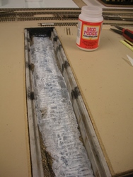 Overall view of the channel with a couple of the short timber “bridges” being test fit across it to carry tracks to the diesel shop building.
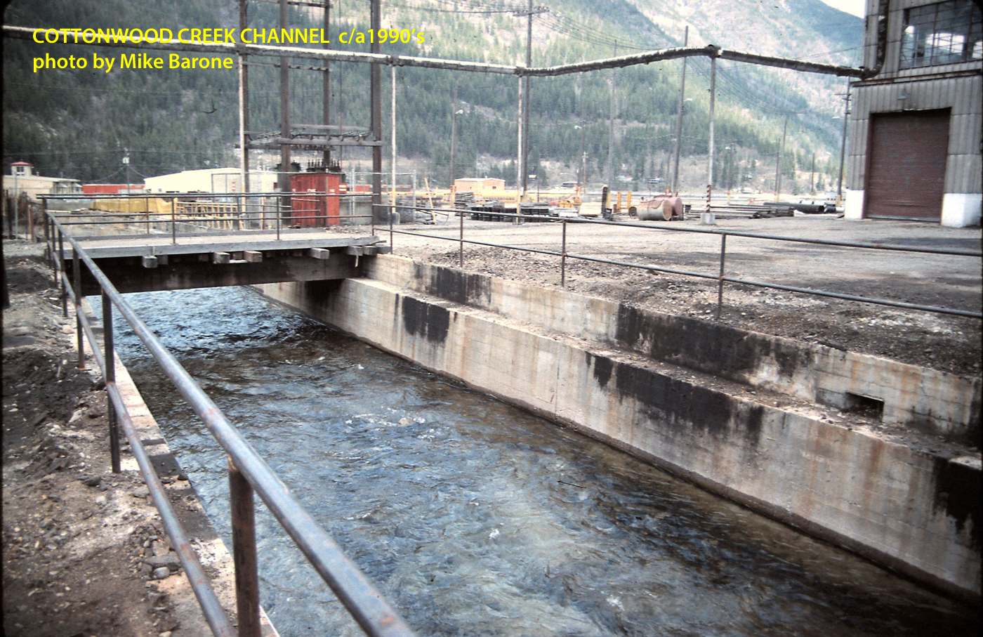
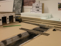 This shot was taken by Mike Barone in the 1990’s and shows the channel quite clearly. Many of the “bridges” across it are now removed due to ongoing abandonment of the rail facilities located in Nelson.
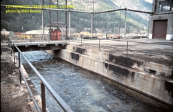
-
june/july 2016 progress photos
-
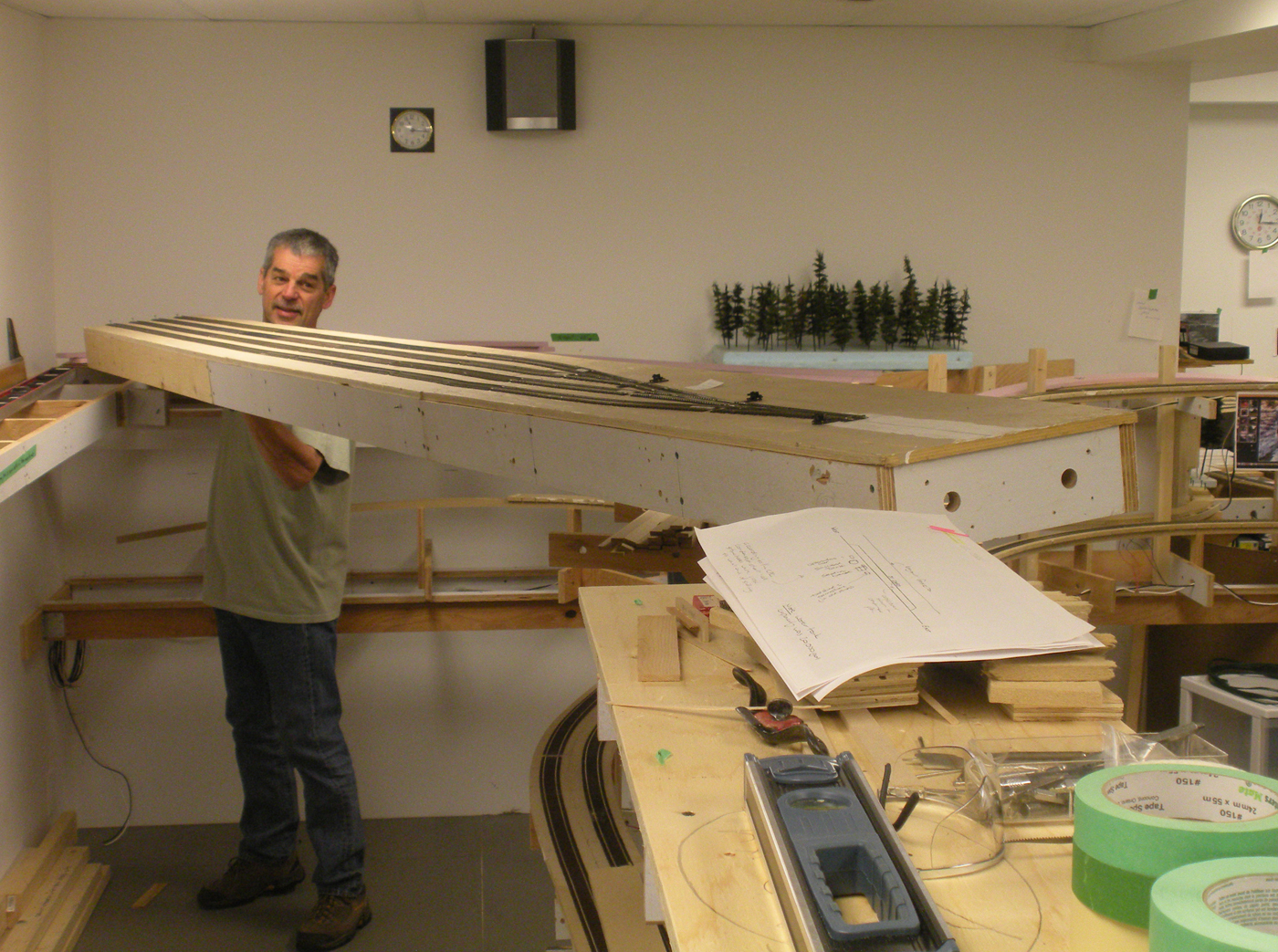
Here we see Ken C lifting up the 12 foot long temporary west staging yard module after we have removed it in preparation for the mainline extension.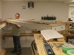
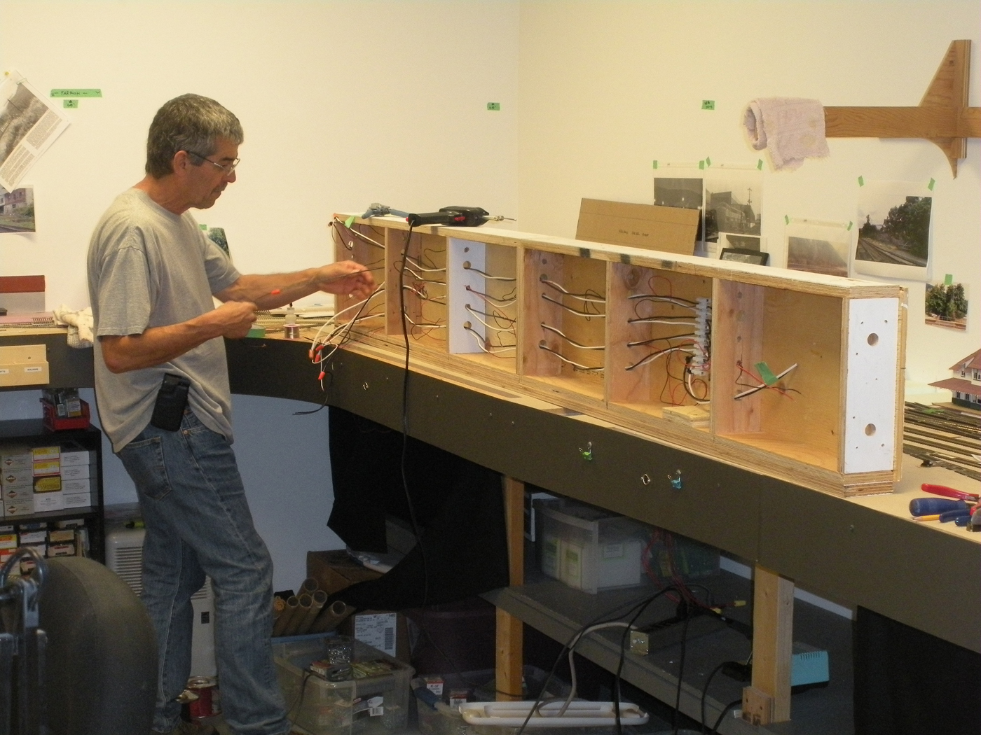
We separated the staging module into a 4 foot and 8 foot section, and here we see the longer one on its side so Ken C can complete some wiring revisosns to it prior to it being reinstalled at the next location. This shows the temporary west staging modules reinstalled. Note that there is a bend in them to accommodate the wall angle. This is why we separated it into an 8 foot and 4 foot section.
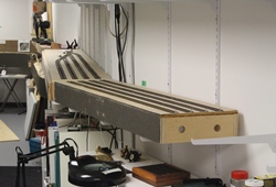
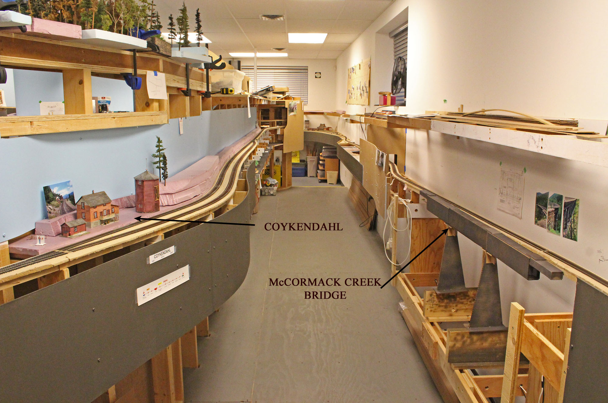
Here we have installed the 66” long drop module to support the McCormack Creek trestle. We are using the cardboard trestle mock up to verify geometry.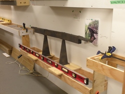 Here we are installing the new spline roadbed west of Castlegar.
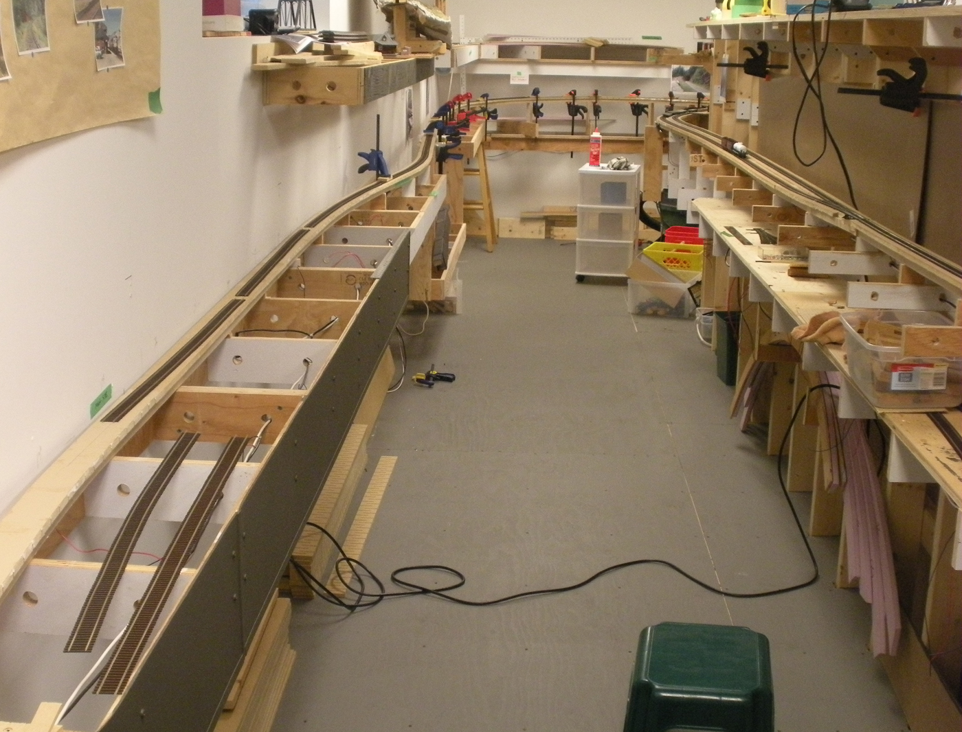
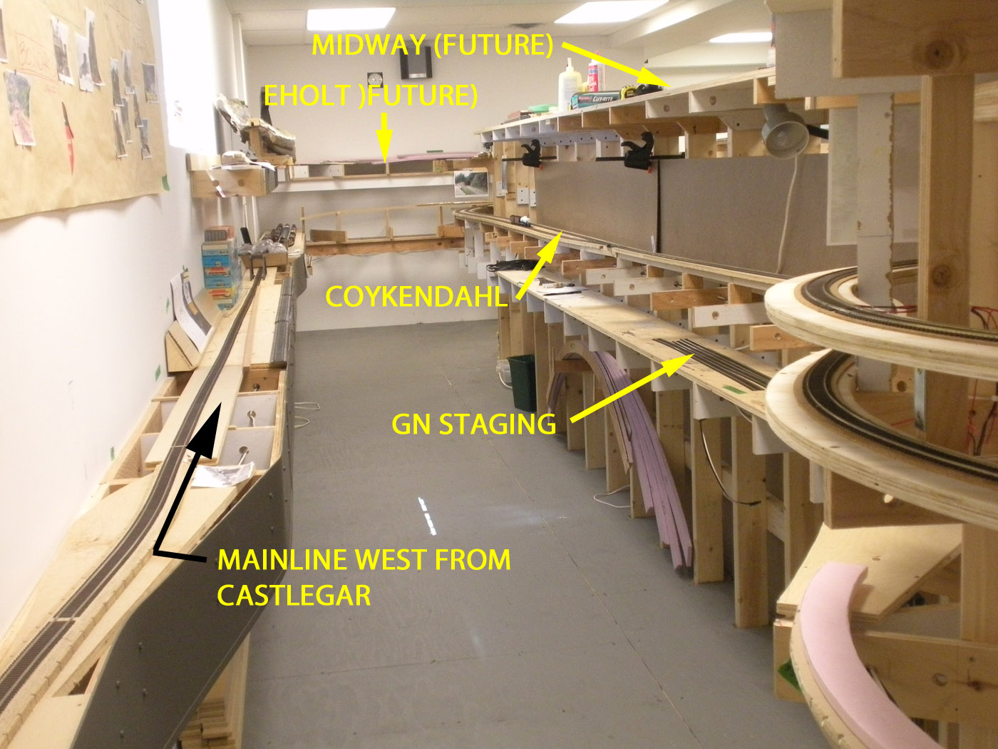
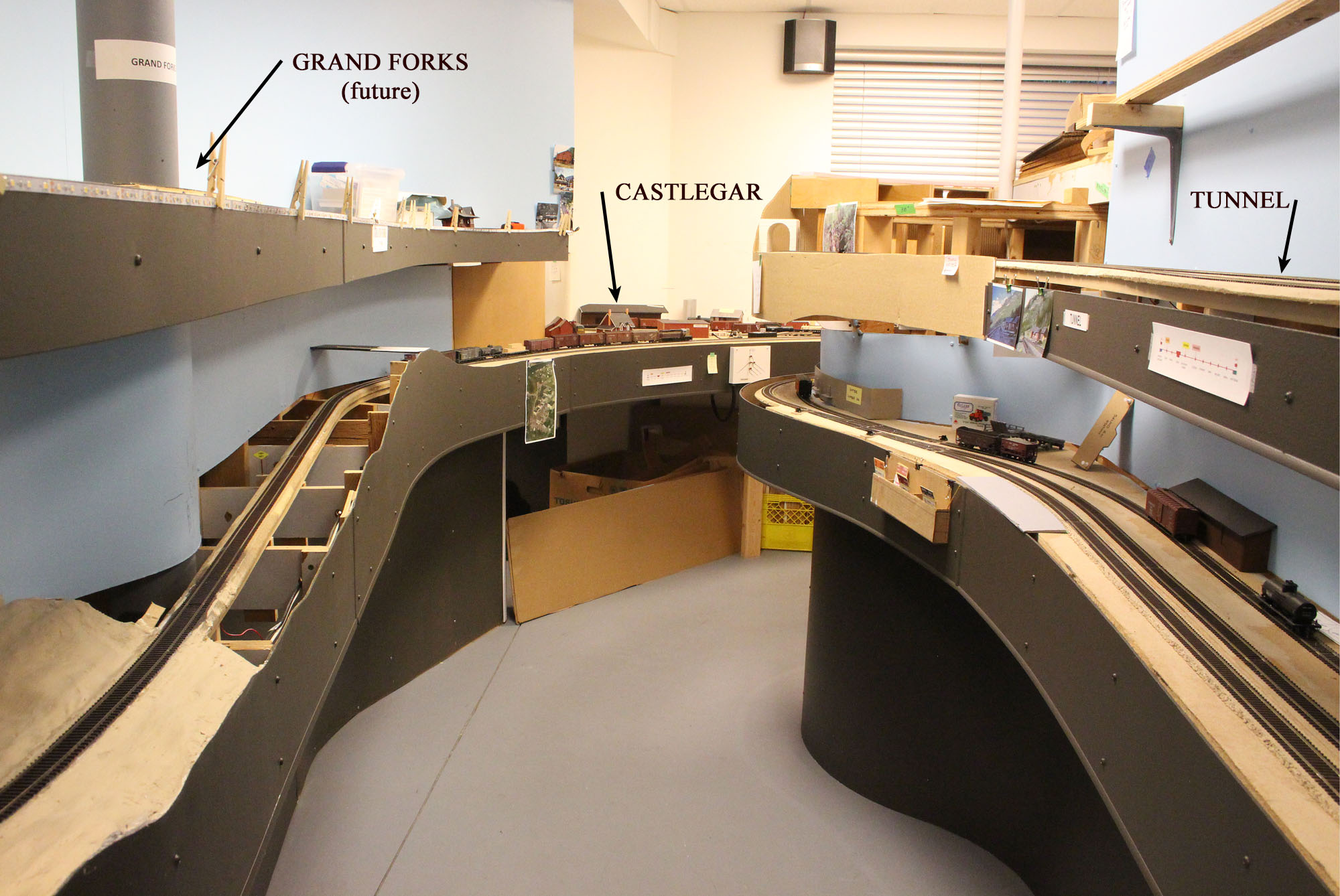
This is a view looking down the aisle west of Castlegar where we are installing the tracks to reconnect the mainline. Coykendahl siding can be seen on the upper right of the photo.
May 2016 progress photos
-
Refer to the plans of the two decks of the layout located under the LAYOUT tab of the web site for help in understanding where these photos were taken.
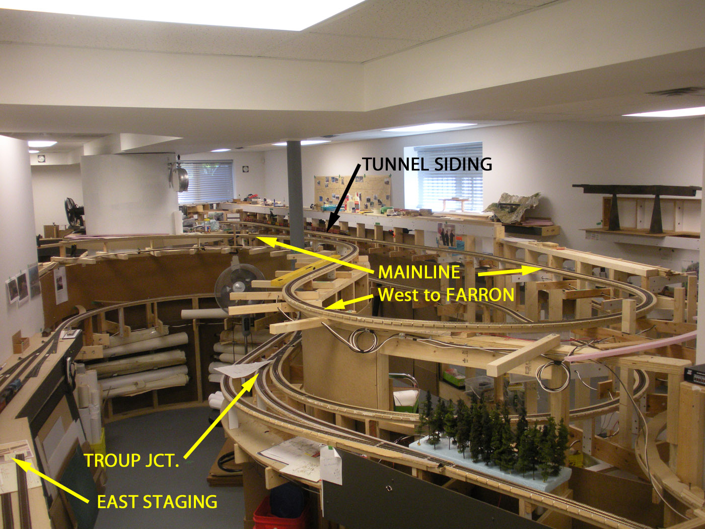
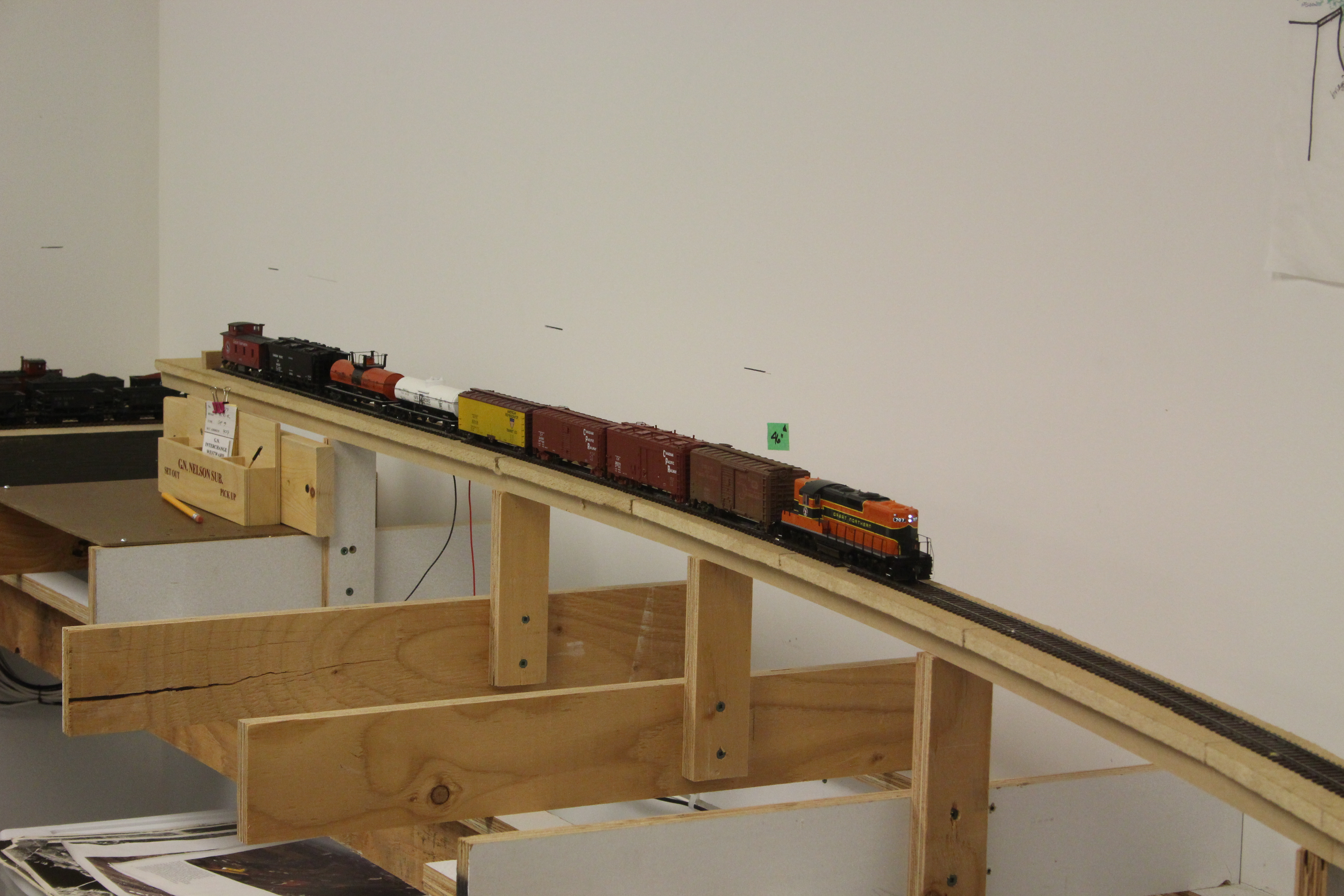
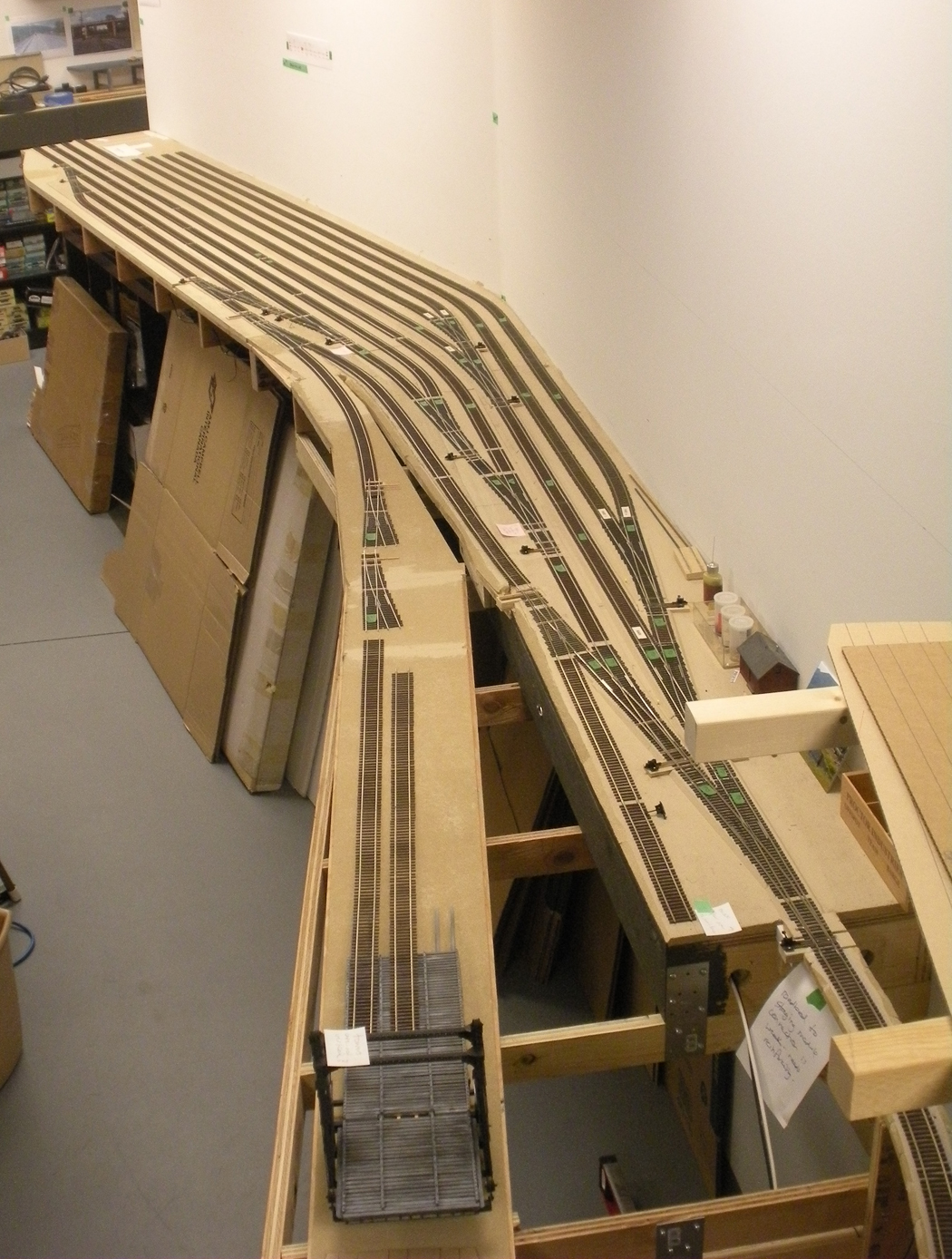
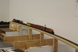
 Overall “helicopter” view of the new mainline running westward from Tunnel siding towards the summit at Farron. This line is ascending at approximately 1.8% and will require pushers.
Troup Junction and the East Staging yard which are on the CP Nelson Sub. east of Nelson can be seen on the lower deck of the layout.
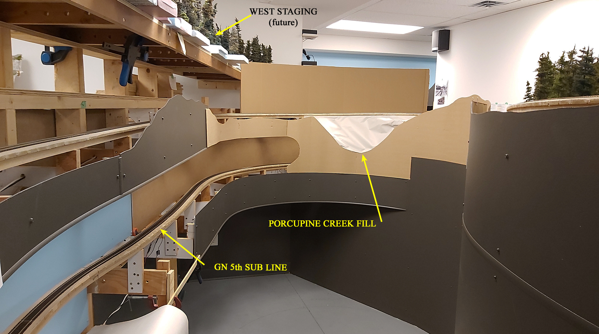
Standing in the near Castlegar looking up the centre aisle of the layout. Tunnel siding which is located at the west portal of the Bulldog tunnel is on the upper deck, and the yard area for the GN at Salmo is under construction on the lower deck.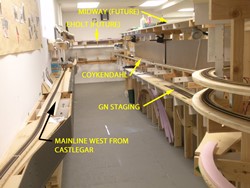 Standing in the aisle near Castlegar looking up the dead end aisle towards Eholt. The new section of the mainline is on the left and the 2% ascending grade will commence where the black arrowhead is. From this point to the summit at Farron will add about 130 feet of mainline to the existing 200 feet.
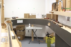
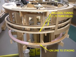 This photo is taken from above Castlegar looking at the end of the newly constructed peninsula where the helix is located. The helix represents the 2900 foot long Bulldog Tunnel. Although there is about 26 feet of hidden track in the helix, the fascia will have slots in it as can be seen in the cardboard mock up piece on the right of the photo.
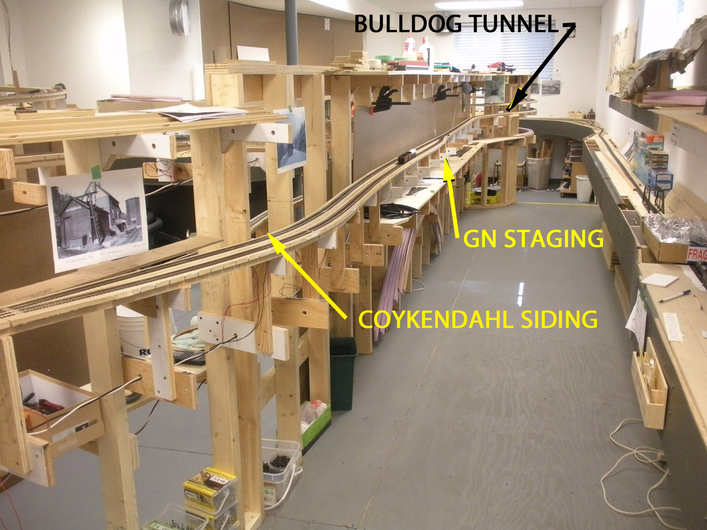
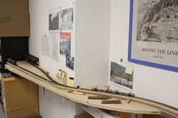
 This view is taken from the Eholt end of the dead end aisle looking back towards Castlegar. The new mainline rises on the right ascends at 2%, passing behind the photographer, through Coykendahl siding on the left, and into the east end of Bulldog tunnel in the distance.
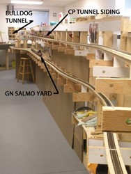
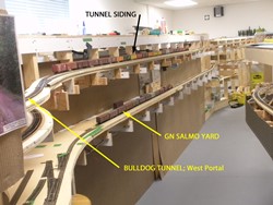
This shot is taken from the other end of the centre aisle looking eastward to towards Tunnel siding and the west portal of Bulldog tunnel on the upper deck. The GN line to the USA passes through Salmo on the lower deck before passing around the end of the peninsula under the helix and into a modest staging yard on the opposite side of the peninsula.
-
-
SEPTEMBER 2015 progress photos
-
Temporary staging stub track representing the GN 5th Subdivision trackage. This will eventually be replaced with a longer line down the yet to be built centre peninsula.
Temporary trackage representing the Slocan Subdivision destinations of the lumber mill and the rail barge slip at Slocan City.
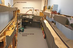
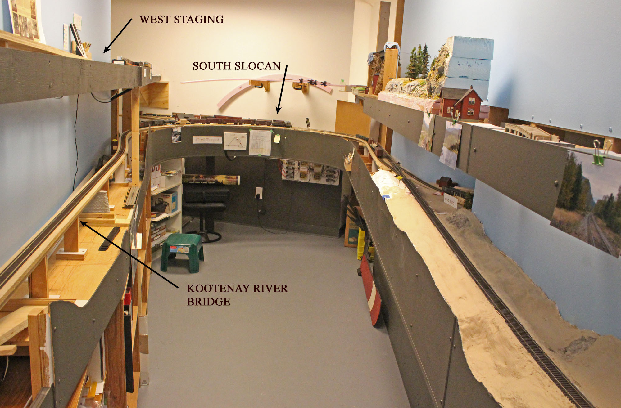
View looking down the aisle towards South Slocan. The Taghum bridge will be on the left where the truss bridge is located. Preliminary framing for the upper deck can be seen on the right side of the photo.
Overall eastward view of the Proctor yard area, which represents the east end of the layout and will eventually be home to the 3 track barge slip that operated there until the late 70’s.
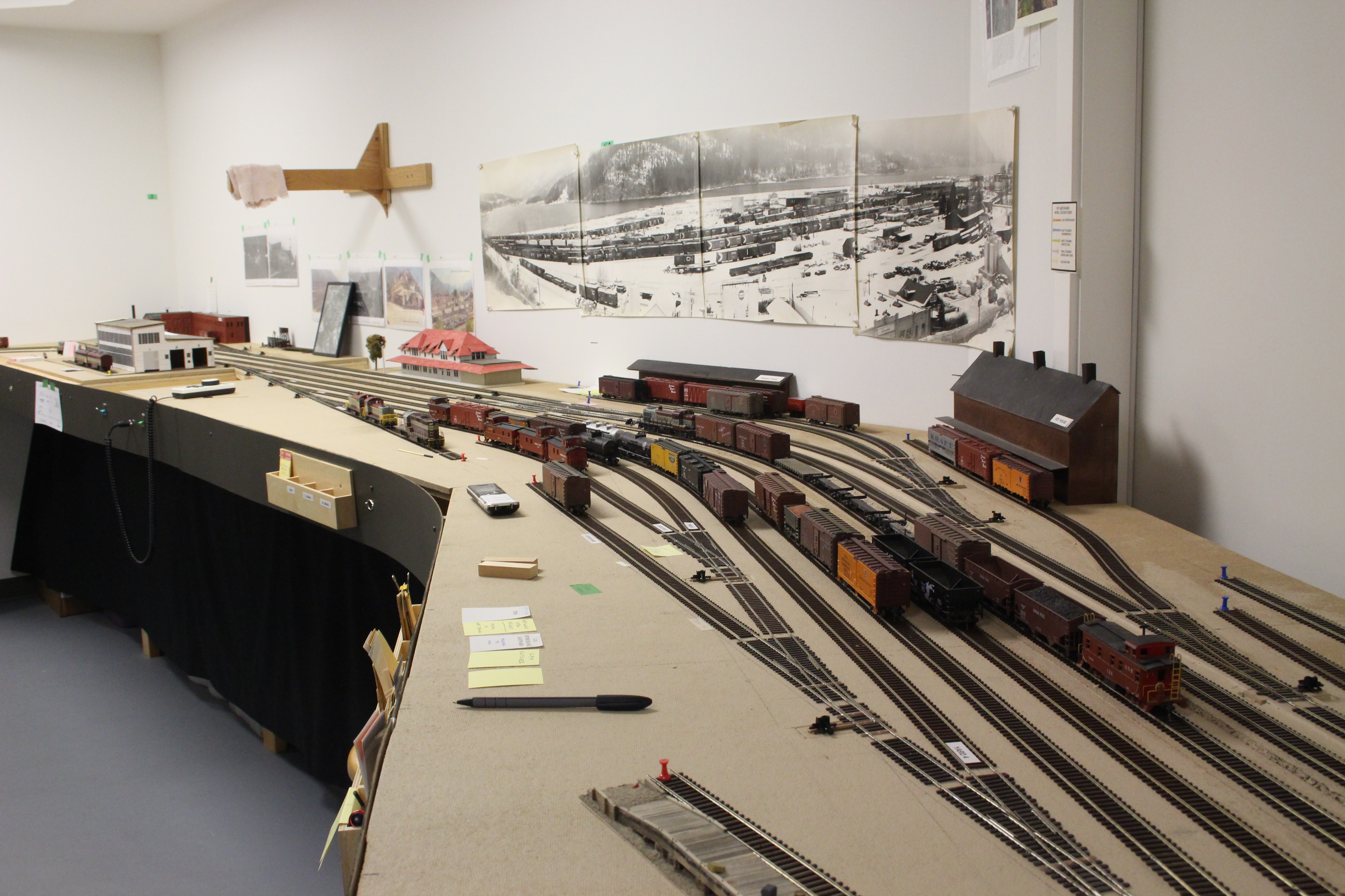
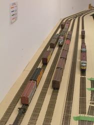
Easterly view looking over the west end of Nelson yard. Most yard tracks are installed now, however, several ancillary tracks are still to be laid. Several local industries are represented along the back wall of the yard with flats.
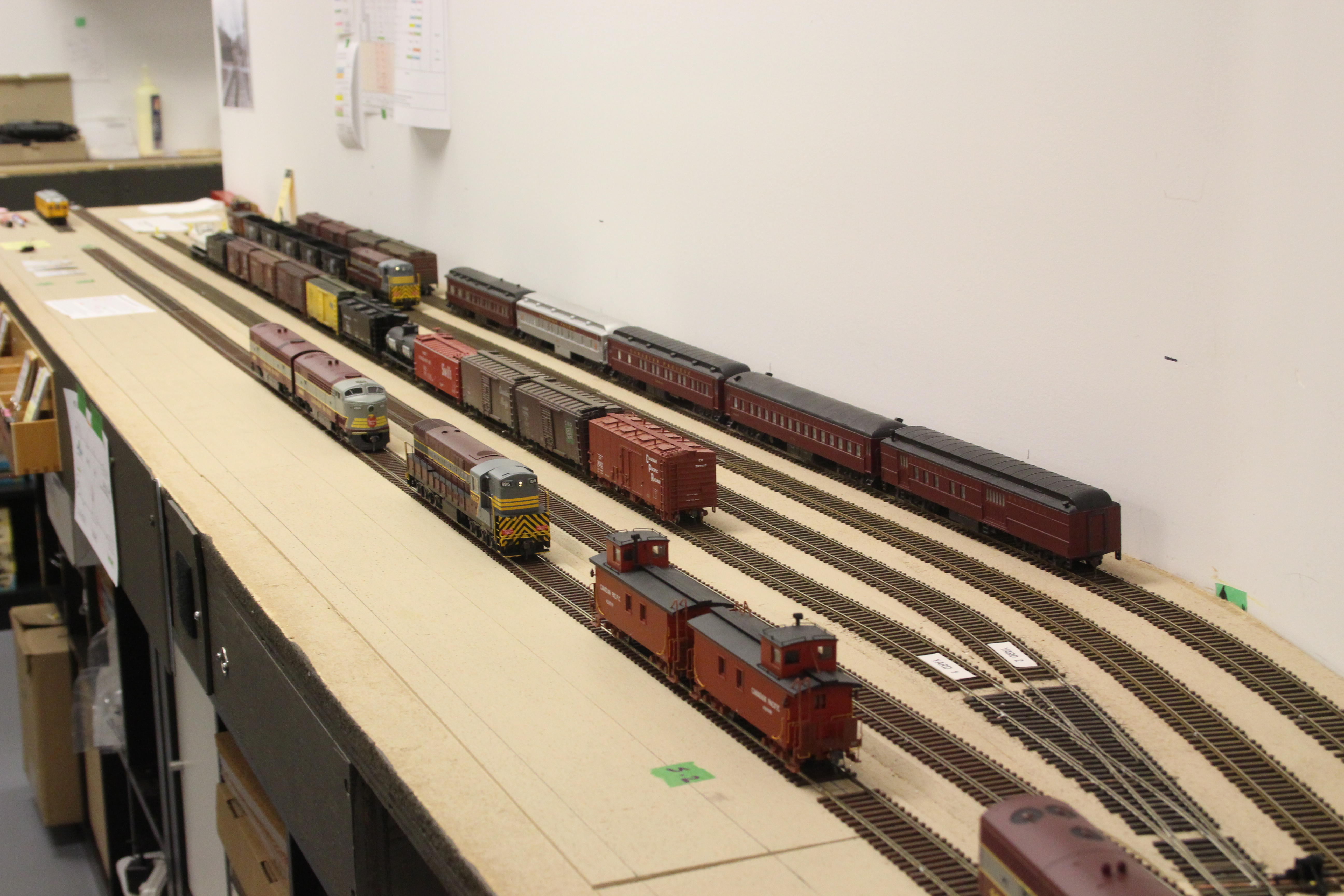
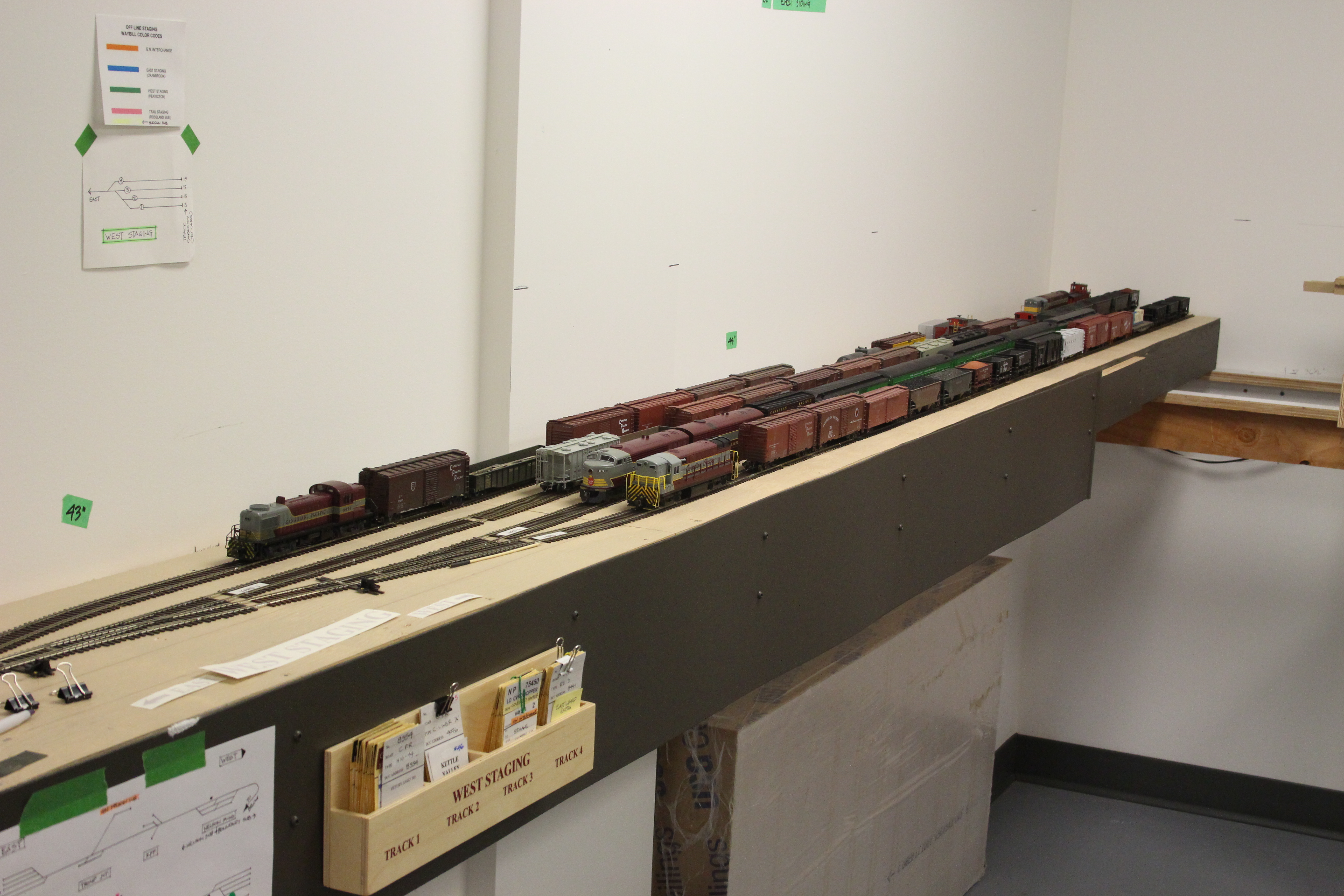
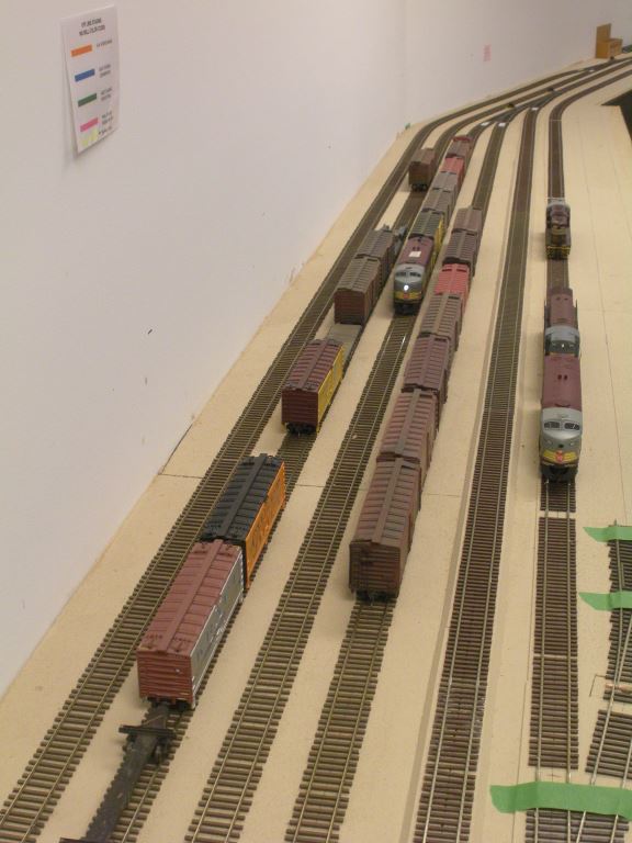
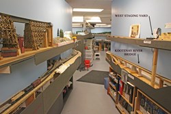
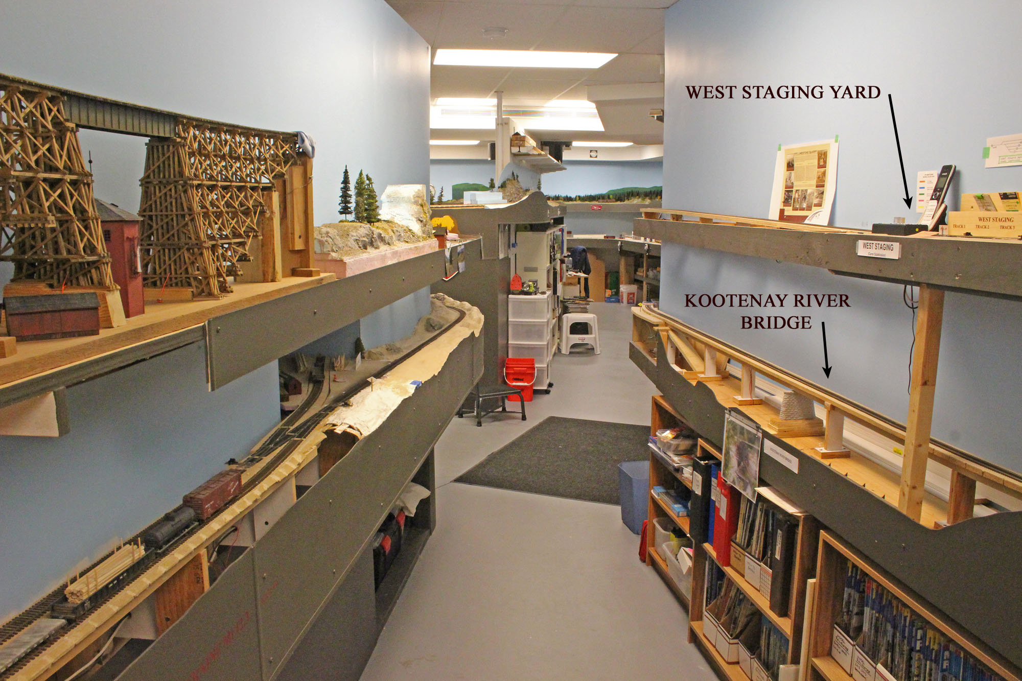
Westerly view of the temporary west end staging yard. It is a 12 foot long module that is designed to be unscrewed from the wall and relocated as the mainline progresses west ward. It is currently at the 200 foot point of the eventual 500+foot mainline.
Overall view of Castlegar yard area. One leg of the Rossland Sub. wye can be seen just to the left of the station where the boxcar sits. The fascia in the upper part of the photo represents roughly where the upper deck will be at Grand Forks.
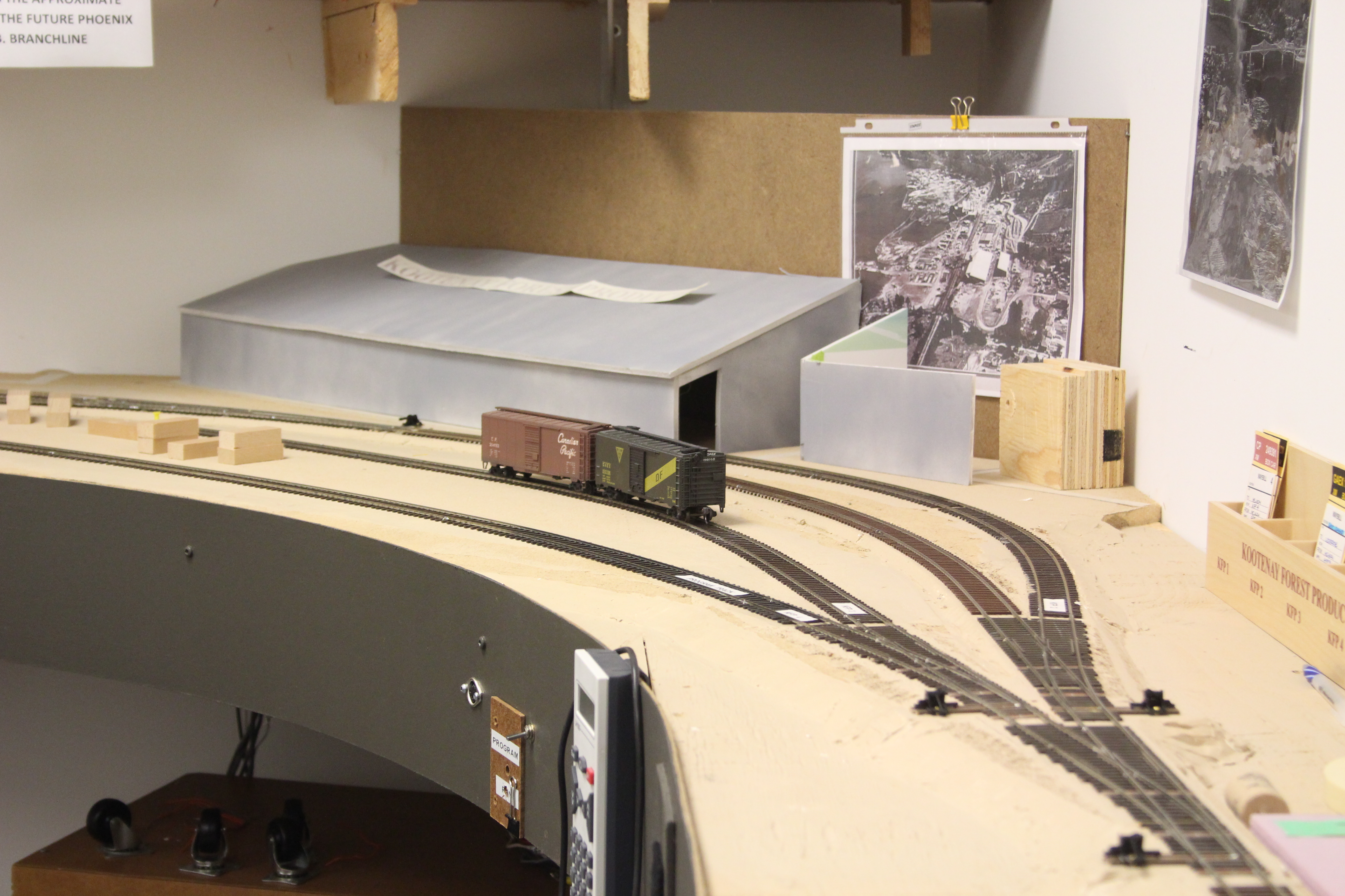
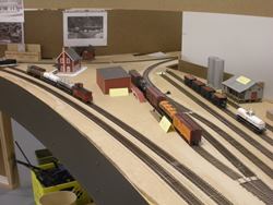
Looking over the mock up for the diesel shops at the east end of the Nelson yard. Some of the placeholders for the industrial buildings can be seen at the back.

View of the Kootenay Forest Products mill site (KFP – no – not KFC!!). Building mock ups made from foam core and painted with rattle cans suffice for now.
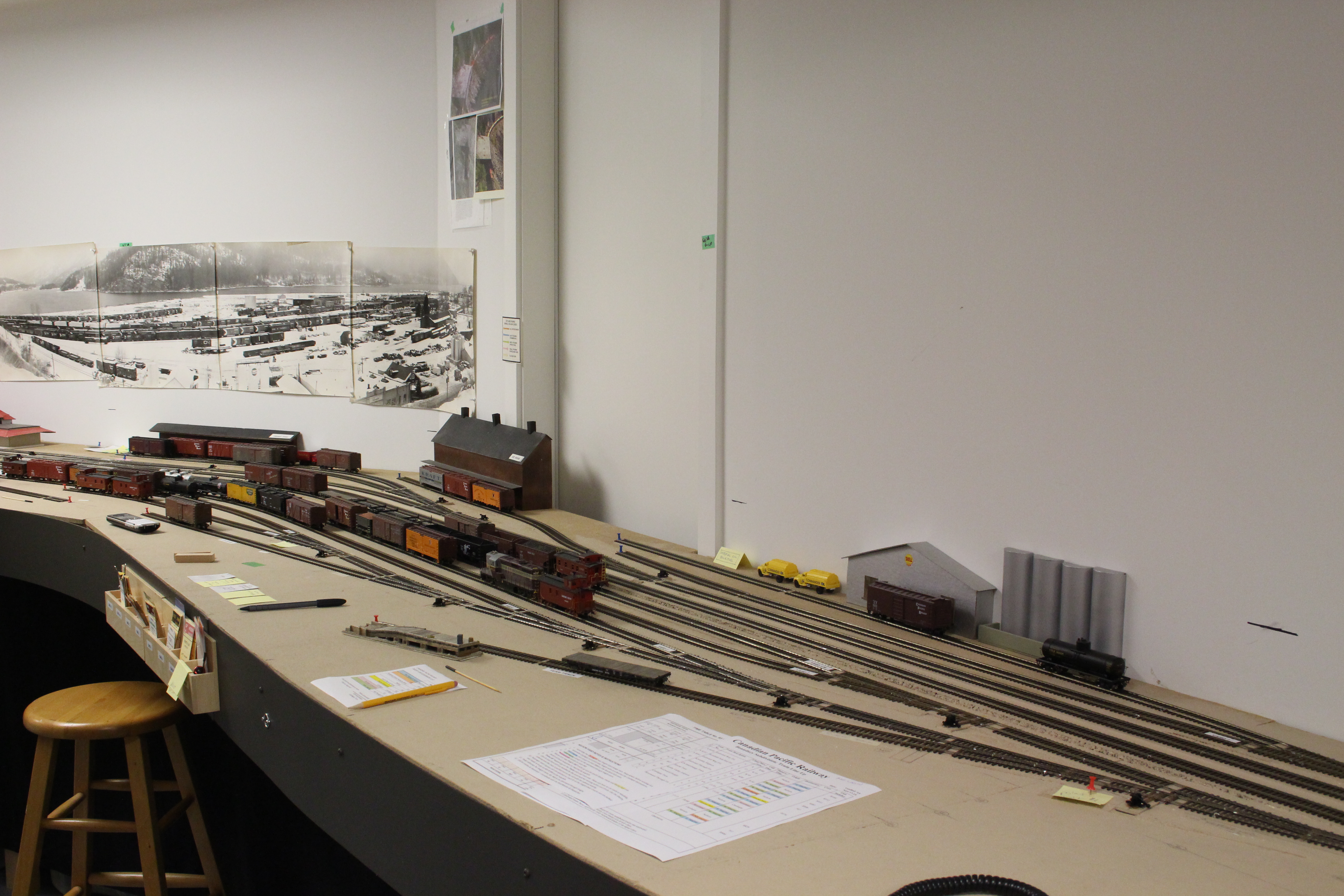
Overall easterly view of Nelson yard taken from the west end. In the photo can be seen numerous building mock ups. The large collage photo on the wall is Nelson taken in the mid 1970’s.
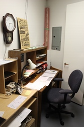
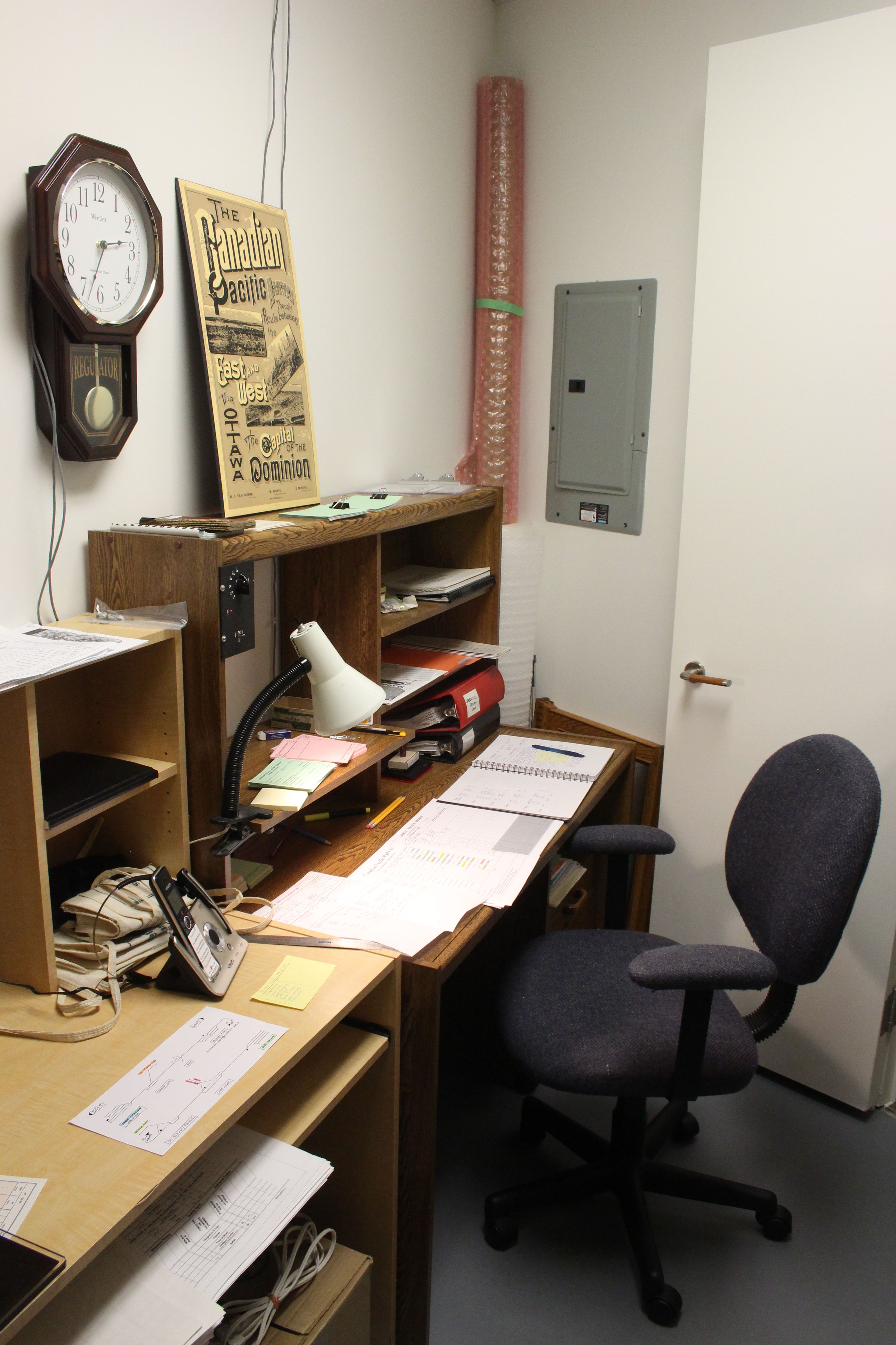
Dispatchers area in a room adjacent to the main layout room. The 4:1 fast clock is located in the upper left of the photo.
-
-
April 2015 progress photos
-
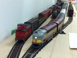
Nelson yard – west end. A westbound C-Liner led passenger train departing while an SW unit switches one of the few yard tracks.
Proctor/East staging yard looking very tidy under the hand of yardmaster John G.

Temporary west staging yard looking pretty full at the end of the session.
Castlegar area – the mainline to the east is in the upper left corner.
-
-
january 2015 progress update
-
-
 Departing the temporary west end staging yard.

Running past the Castlegar station (yes – I know that really isn’t the actual station). The line to the Rossland Sub branches off just to the left of the station, and some of the yard tacks can be seen beyond the train in the background.
Running past the South Slocan station – again, a substitute building at this time. This is a location of a wye and the junction with the Slocan Sub. – the yellow TH&B car in the background is on one leg of the wye and the other leg is just to the left of the station.
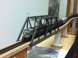
Crossing a mock up for the main truss span of the Kootenay River bridge. The total bridge on my layout will be about 6ft long – and that only includes 6 out of the 9 spans!
Crossing the swing gate at the room entrance - yay!!

Crossing the swing gate. On the right hand end – you can see some of the hardware that Ken built to assist in fine tuning the vertical and horizontal alignment of the gate.

Running into the west end of Nelson yard – we will have numerous industrial flats along the back wall – like the Shell bulk fuel mock up that is in the background.
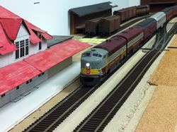
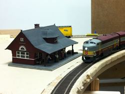
Approaching the Nelson station – you may recognize this slightly worn mock up from the previous layout. The freight shed and ice house can be seen in the background – also mock up buildings from the previous layout.
Running through the Kootenay Forest Products mill site – yes the mainline literally did run right through the mill site!
Taking the main in the Proctor/east staging yard. Lots of trains in there right now. This will be an active yard and will eventually have the 3 track rail barge slip that serviced Kaslo, Lardeau and a few other locations up the Kootenay Lake. This barge operation lasted into the 70’s.
-
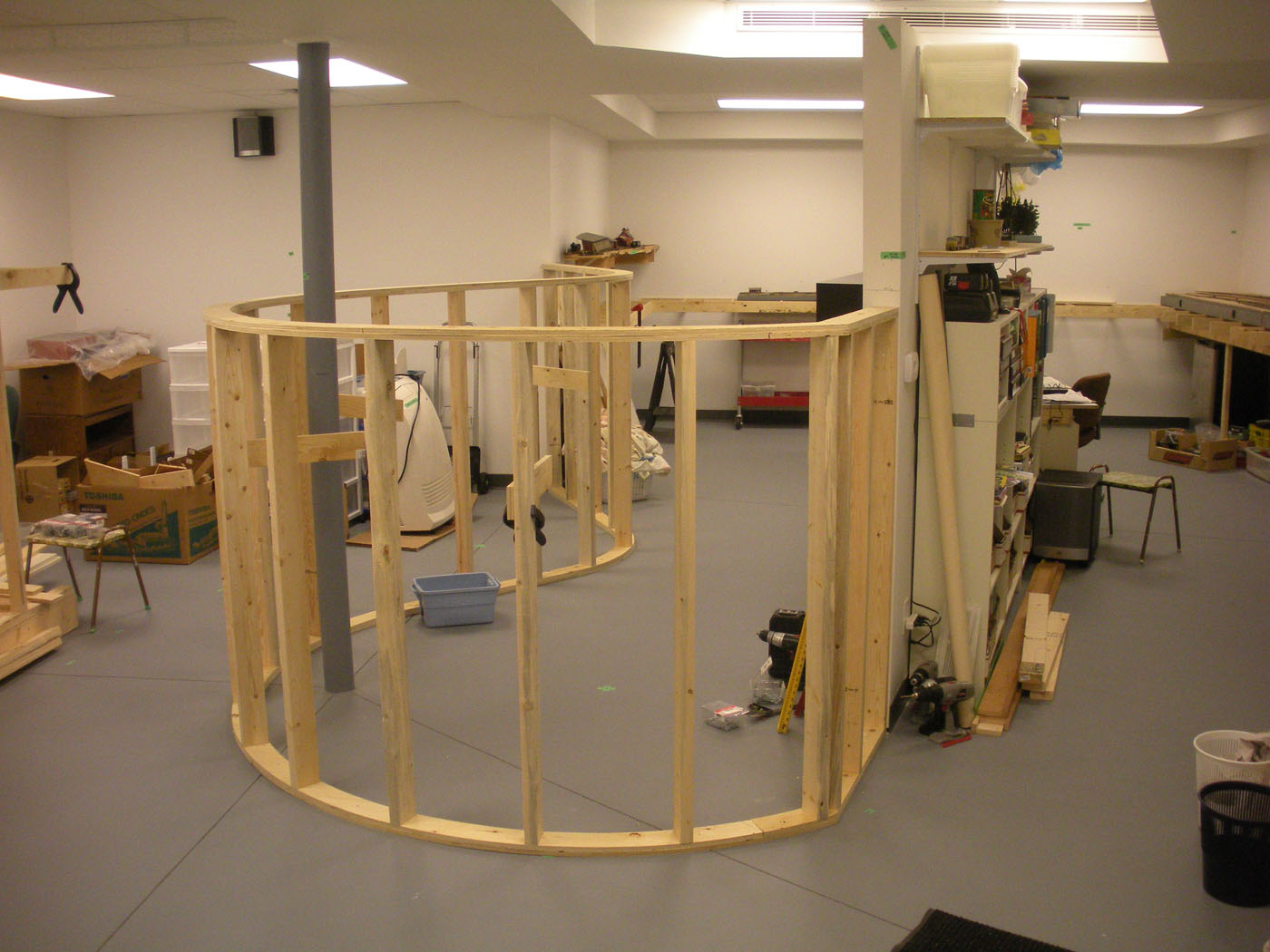
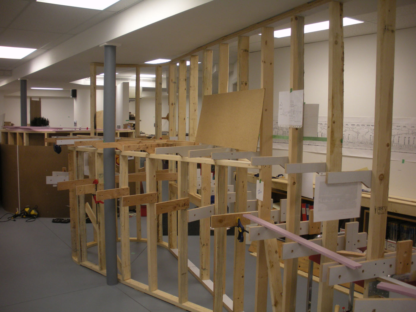
early layout framing
-
.jpg)
.jpg)
-