-
techniques
-
We are often asked about how we designed and/or built various aspects of the layout, so this section is intended to provide some information in that regard. Many of these practices are not necessarily my own, nor have I actually built everything myself, therefore I have tried to note credit where ever I can.
There is also no order to how these have been presented below. Feel free to contact me if you would like to discuss any of them in more detail, or have specific questions or thoughts.
October 2019 | CPR Boundary SubH.O. Scale cpr paulson snow shed (Mi 63.7 Boundary Subdivision, Kootenay
(Mi 63.7 Boundary Subdivision, Kootenay Division)
This snow shed is custom designed and constructed for a specific location on the mainline of my home layout of the CPR Boundary Subdivision c/a 1962. It achieved a Merit Award in the NMRA Achievement Program and was the last model needed to also achieve my Master Builder; Structures certificate.
The model is located on a 1.1% grade and a 59” radius curve on the upper deck of my layout. It is scratchbuilt using Mt. Albert dimensional lumber pieces & sheetwood, and is based on my own sketch drawings in addition to modified CPR Standard plans. The only commercial parts are the fire barrels & NBW’s. The 62 individual pad footings were 3D printed based on my sketch plans.
The structure (except the roof decking) was built board by board using a variety of jigs, clamps and various tools as can be seen from the photos below. The shed is built entirely to prototype dimensions and geometry. Excluding the roof sheathing, this model consumed close to 16,000 scale feet of lumber and has over 1100 individual pieces in it – ranging from 2ft to 65ft in scale length. For example, there are 240 - 10ft long 3x10 braces, and 190 - 2ft long 4x12 pressure blocks in the model!!
There is the appropriate number of fire barrels on the roof for my era. NBW’s are installed along the exposed framing on the downhill side of the structure and on the end frames only since that is all that can really be seen. The downhill side of the shed is supported on 62 individual pad footings, and the uphill wall frames are supported on cribbing and retaining walls that are integrated into the layout scenery base. The retaining wall immediately uphill from the track was covered with a reduced and edited copy of a drone photo taken in 2017 of the actual stone walls that remains next to the rail trail.
The model conforms to the standard CPR prototype plans with slight modifications to suit this specific structure. All framing is exactly as the prototype was, with the exception that the shed is 15 feet shorter in overall length than the prototype. The geometry of the framing elements is completely accurate.
Because the roof plane is not level due to the curved footprint, I assumed that the planking would all end at certain roof beam locations since the prototype plans are for a straight shed and no information was located for a curved shed. This is why the roof sheathing was installed in 5 separate pieces with joints over the main roof beams.
There is absolutely no lettering on the prototype structure, and I confirmed with an actual CPR Boundary Sub. Locomotive engineer that these sheds had no mile boards on them.
All the scale stripwood was lightly sanded and then colored using my own stain mixes made from Black shoe dye and Isopropyl Alcohol. I used 2 slightly different intensities to capture the variation in the wood that is seen in the photos. The NBW’s were painted rust color and then had an overcoat of Raw Umber acrylic paint wash. The roof decking was stained with the same mixes as was applied to the stripwood. Each individual roof panel was stained to make the sheetwood look more like individual boards.
The roof was weathered further by rubbing some play sand into the sheeting to dull it down. Further rocks, dirt and vegetation as can be seen from the prototype photos will be added loosely onto the shed once it is installed on the layout. Locomotive exhaust effect was created using powdered black pastels brushed on to the underside of the structure and on the face of the end frames in line with the track centreline.
The 3D printed concrete footings were painted using Scalecoat Concrete paint and brushed slightly with powdered pastels to tone them down. They will receive additional weathering as part of the process of integrating the structure into the layout.
Here are a series of photos summarizing the construction process in a chronological sequence;
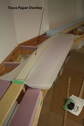
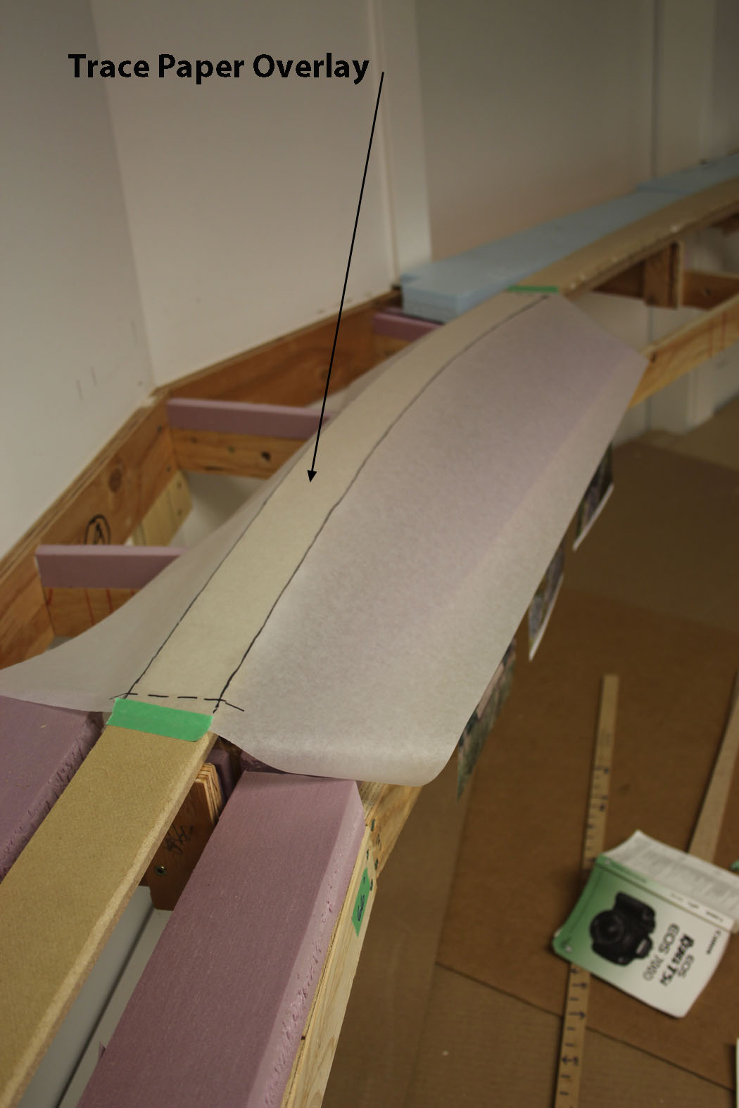
A drawing of the as constructed roadbed was made by overlaying a piece of sketch trace paper on the completed roadbed geometry to determine the overall base configuration of the shed. Because the shed is on a curve, the standard plans and prototype photos I had did not help understand exactly how the shed was built. So, I decided to construct the shed in five equal wedge shaped sections.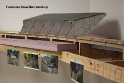
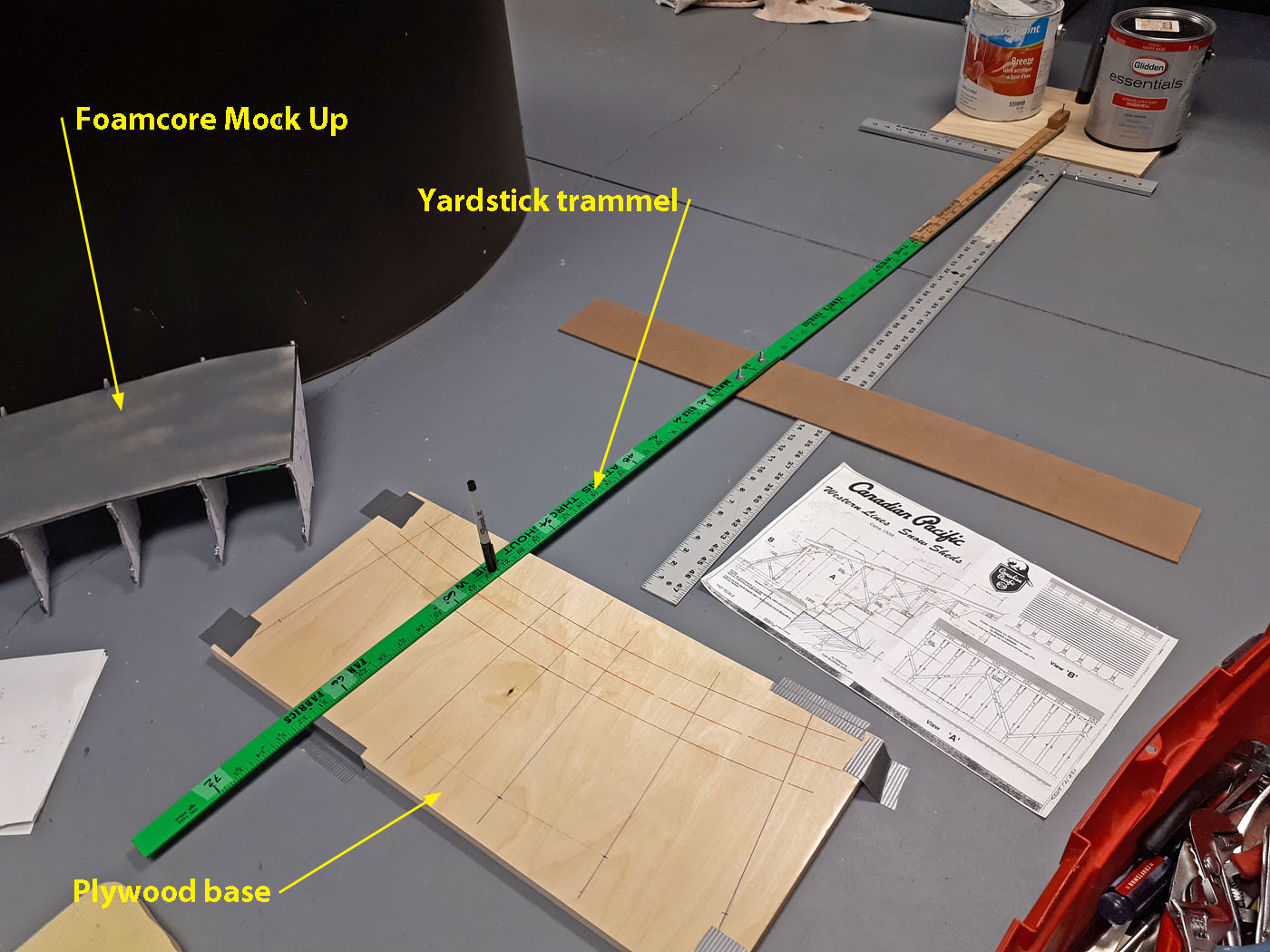
A foam core mockup of the shed was made using photo copies of the scale plans and the sketch footprint plan. This mock up shed was then test “fit” on the layout to verify things before launching in to the actual construction.
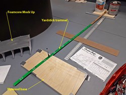
Based on the previous steps, using a yard stick trammel, a plywood base was developed to build the shed on. This was done to facilitate the shed being built upside down – e.g. roof down. In the photo you can see the outlines of the five wedge shaped sections.
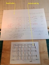
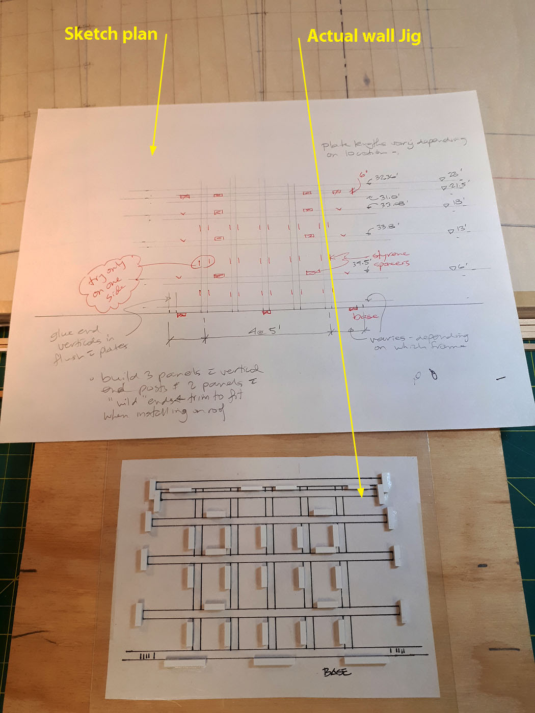
Another sketch (top of photo) was developed for the typical wall framing. Once satisfied with it, a more accurate plan was drawn which was then glued down to a piece of plywood, and overlaid with a piece of clear styrene on top of which the actual jig was made. The jig is designed to be used for the five different heights of walls that progress up the slope and it also accommodates the different lengths of each wall element.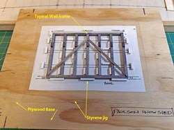
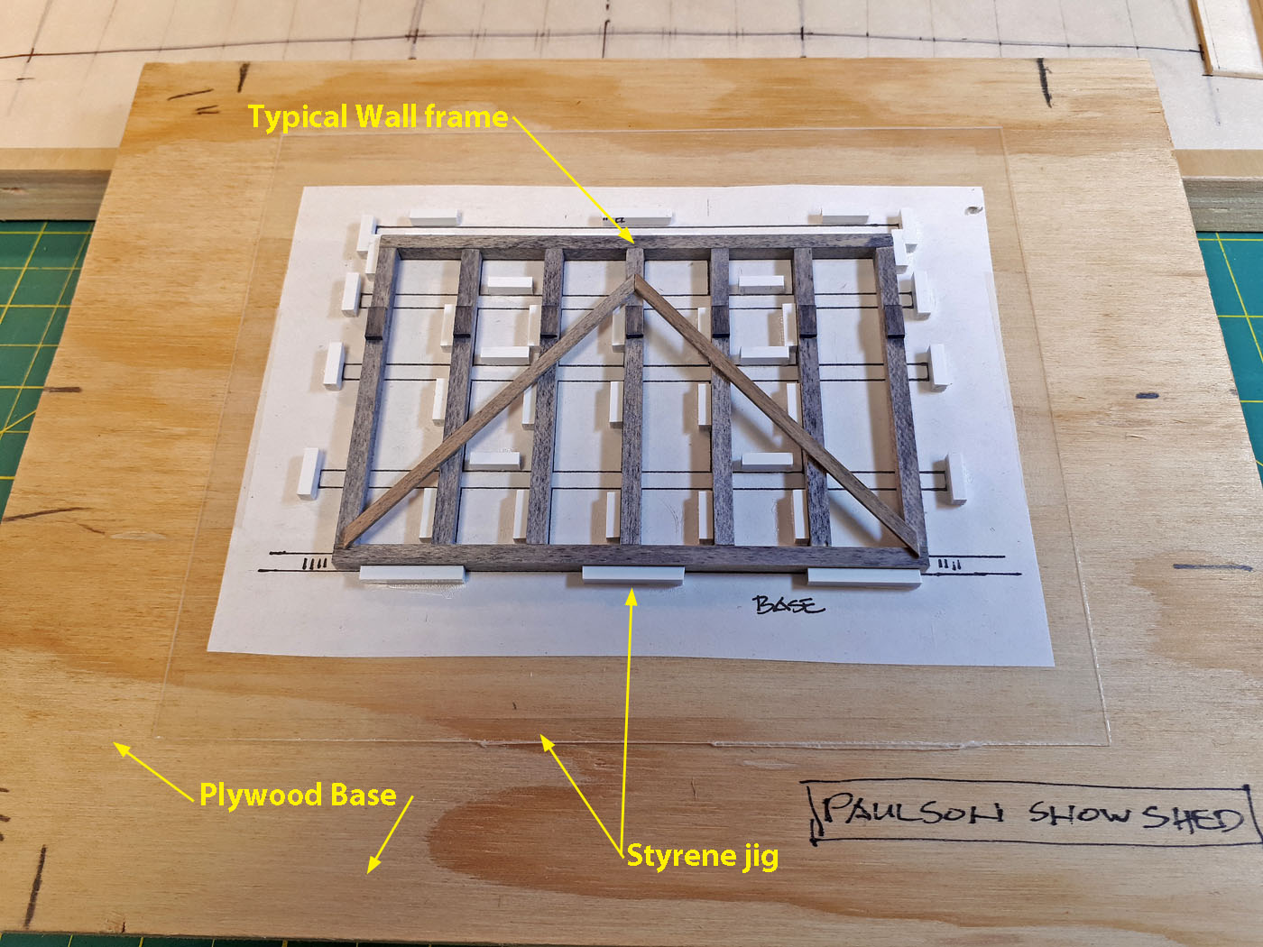
Here we see a typical wall frame being constructed in the jig. This particular wall is braced because it is located adjacent to the track on the uphill side.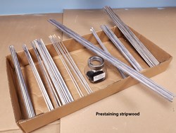
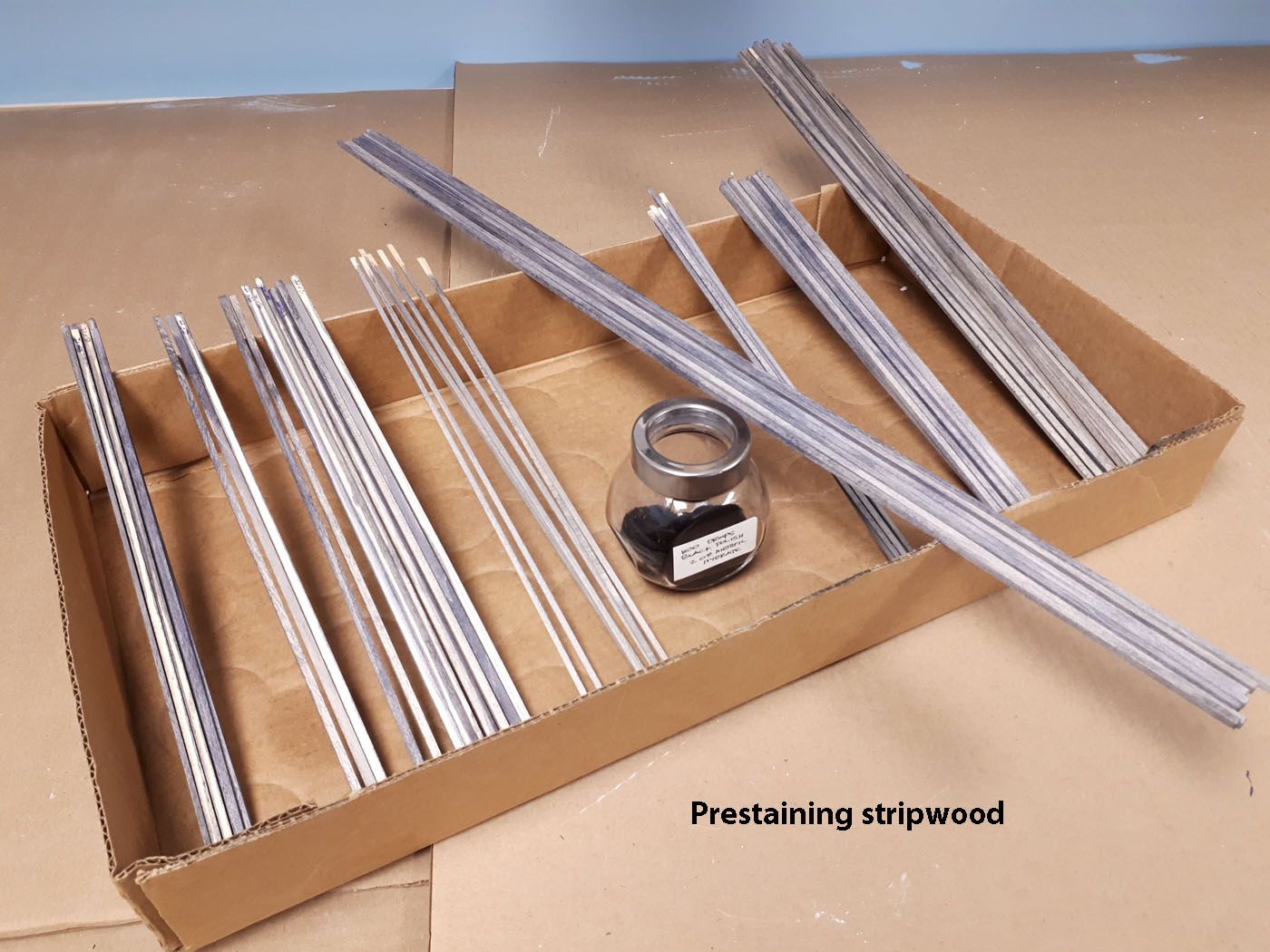
All the strip wood was inventoried, organized and stained with a custom mix.
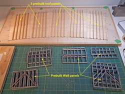
Five separate roof panels were built upside down on the plywood base as shown on the top of the photo. These roof panels were secured to the plywood construction base with oversize model track spikes to keep them secure. Several of the wall panels built using the jigs are seen in this photo too.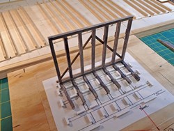
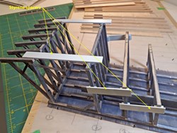
The downhill wall frames had outrigger framing and bracing added - again using the jig.
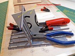
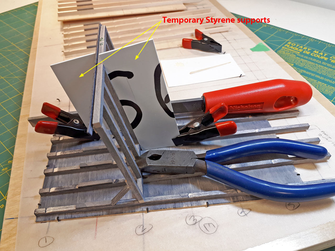
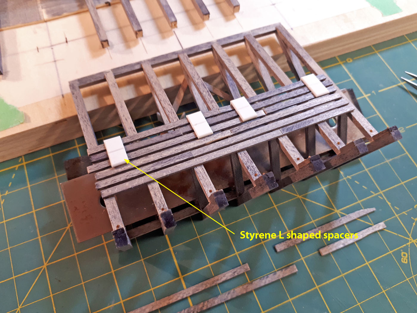
Sloped styrene shapes were used to hold the wall frames at the proper 1:5 slope while being glued to the inverted roof panels. The sloping roof beams were notched to accept the top plate of the wall frames.
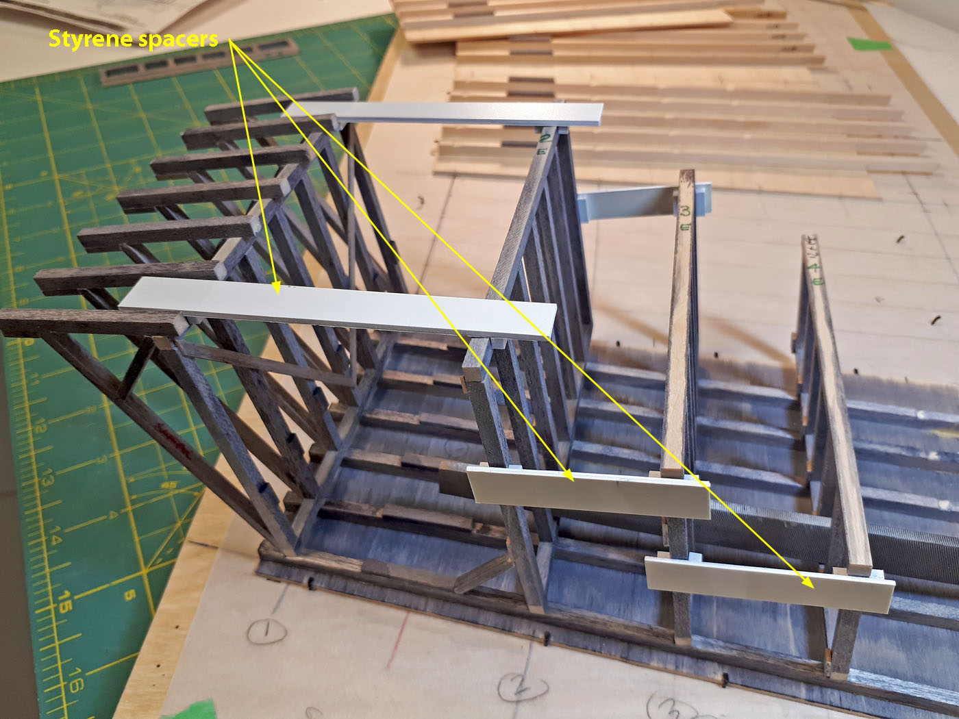
Several styrene spacers were built to use in securing subsequent wall panels in proper alignment and angles while the glue was drying. This was one of the challenging parts of the construction since the wall panels need to be kept at 10ft spacings as they progress up the hillside. Each wall panel was labelled on the bottom with an alpha-numeric code to keep them organized.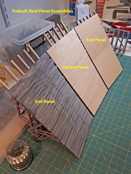
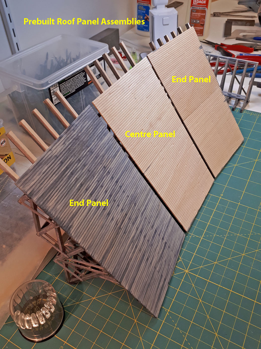
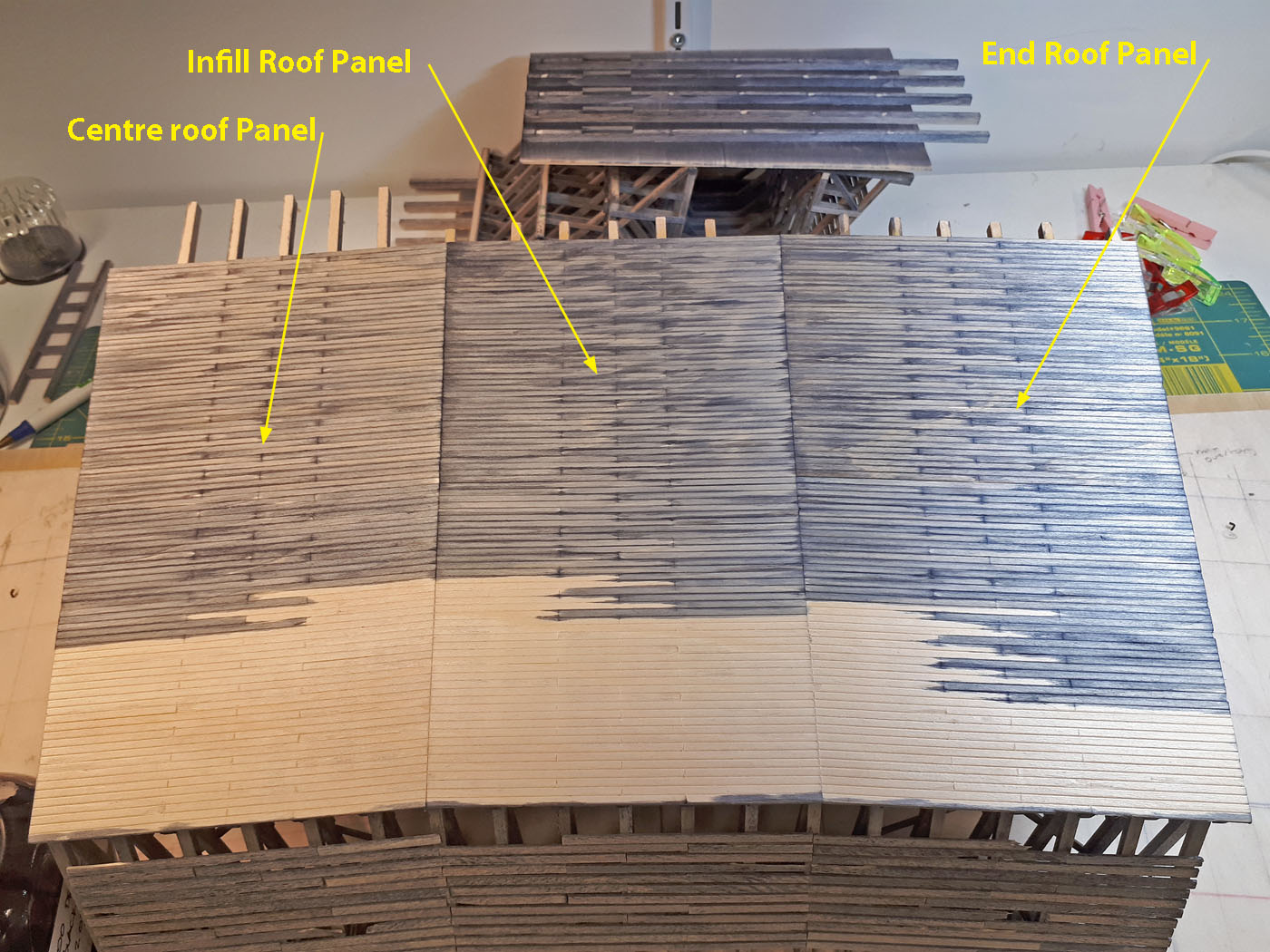
The two end sections and the centre section were built as sub-assemblies complete with roof sheathing on top of the plywood base. The two infill sections between these will be custom built in place on the plywood construction base.
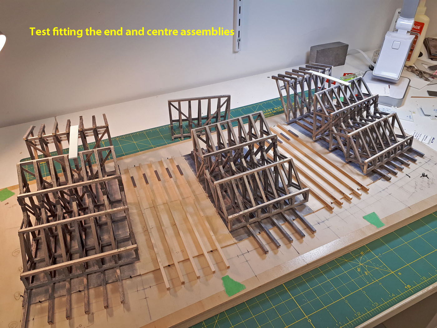
The three subassemblies were test fit to gain an understanding of how the roof slopes will be achieved.

The downhill sloped wall frames receive 3x10 protective planks using styrene spacers to achieve proper spacing. Numerous planks were distressed to capture the worn look of the prototype in the 1960’s.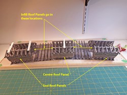
The 3 subassemblies received the protective planking and the infill roof panels received their stains.
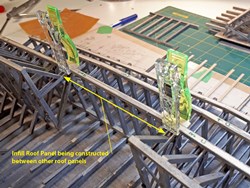
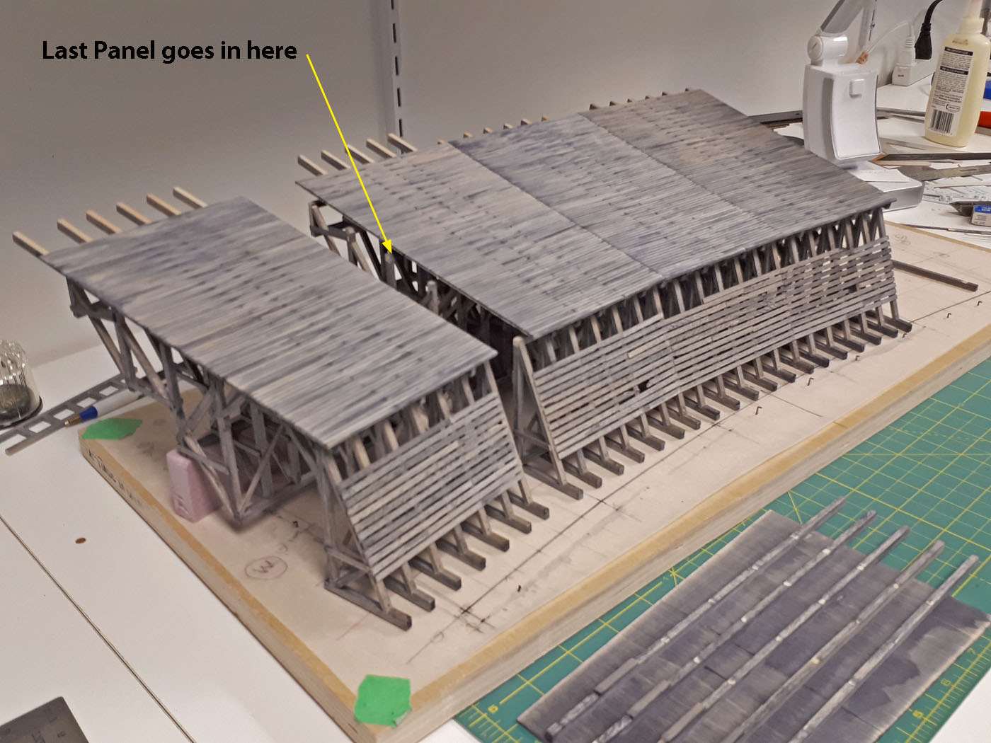
The two remaining infill sections were constructed in place and required angled shims between the 3 completed subassemblies and the plywood base to achieve the proper geometry and roof slopes between the 5 individual sections. This was by far the most challenging step to the construction and took several trial attempts to get it right and ensure the shed sits level and the framing was all plumb.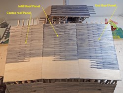
Here we see one completed infill section built between the previously completed end and centre sections. The roof received notches to look like individual planks and random distressing, and was stained in a staggered pattern to create more of an individual plank look.

Here we see 4 of the 5 completed sections of the shed, with only one final infill section to be completed.
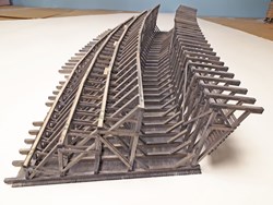
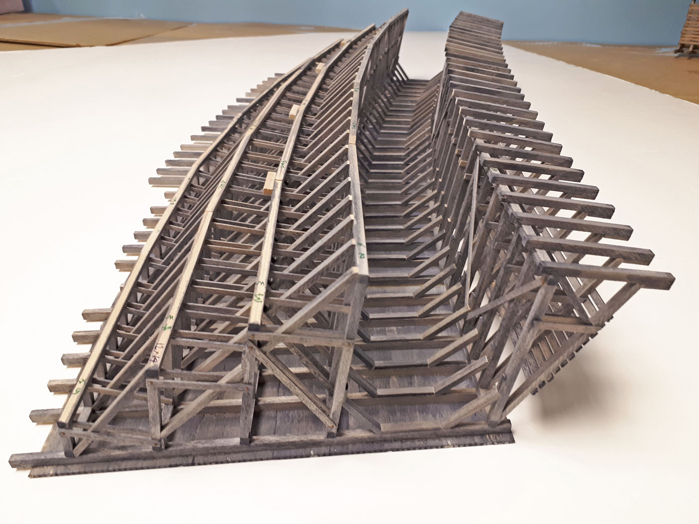
All the appropriate internal bracing was included in the model as can be seen from this photo. It was very tricky getting it all in there for sure.
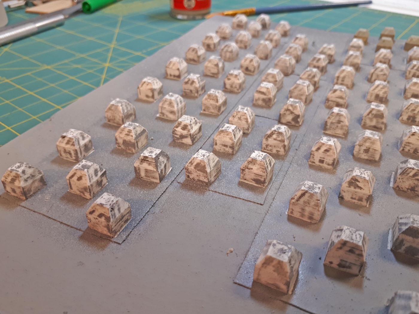
The pad footings were 3D printed and needed some filing to clean up before being painted and installed.
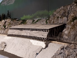
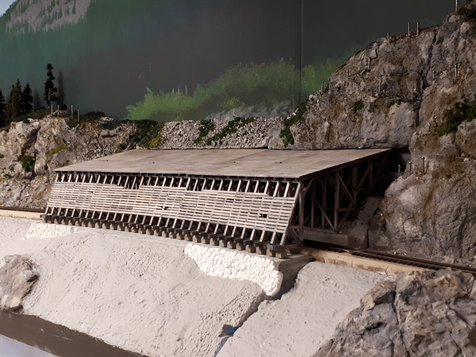
A progress photo of the shed temporarily positioned in the eventual location on the layout. The scenery is not completed yet, however, this provides a pretty good “feel” for the scene.
Below are a few documents related to this project including; the actual CPR prototype snowshed plan W.L.S. – 22 and a couple of my working sketches for various aspects of the modeling work. My apologies for the roughness of the sketches – I am not a CAD guy – I like hand drawing stuff.


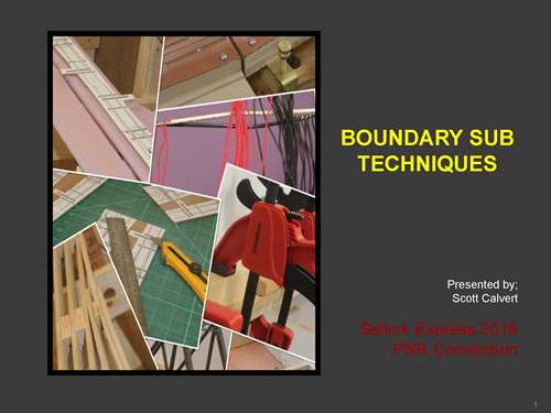
- May 2016 | CPR Boundary Sub
Selkirk Express 2016 clinic - PNR Convention
Click the Image download the presentation.
-


- November 2015 | CPR Boundary Sub
novel construction technique clinic (presented at vte 2015)
Building a very large & complicated multi deck layout such as the CPR Boundary Sub. Version 2 can consume significant time and resources. This presentation will show us how the build crew developed and applied various techniques and methods to speed up construction while achieving an appropriate level of quality and aesthetics.
Due to limited time for the clinic, the presentation is done at a high level, and many of the topics will be further expanded in this section of the web site in the future.
Click the Image download the presentation.